Electric Arc Furnace Transformer
ProductOverview
An electric arc furnace transformer steps utility voltage down to the few hundred volts and tens of kiloamps that an arc furnace needs to melt steel scrap. It is one of the most heavily stressed transformers in industry. The arc is an unstable, non-linear load: it draws harmonic-rich current, it short circuits every time an electrode bores into cold scrap, and the demand swings from a near short circuit at melt-in to a steady refining arc within one heat. A furnace transformer therefore carries far more conductor copper on its secondary than a distribution transformer of the same rating, has a wide-range on-load tap changer to set arc power, and is braced internally for repeated electromagnetic shocks.
Ratings commonly run from 40 MVA on a small meltshop to over 150 MVA on a modern ultra-high-power furnace. The primary is usually 33 kV class, fed from a dedicated furnace bus. The secondary delivers 200 to 1,500 V and 30 to 120 kA per phase. Because the secondary voltage must change while the furnace is energised, the on-load tap changer is a defining feature, often with thirty or more taps so the operator can pour maximum power into cold scrap and then back off to a soft refining arc.
Core and magnetic circuit
The Magnetic Core is a three-limb stacked design built from grain-oriented silicon-steel laminations of 0.23 to 0.30 mm thickness, laser-scribed to cut loss, and assembled with mitred step-lap joints to reduce no-load loss and noise. Flux density is held lower than in a utility transformer because the harmonic content of furnace current would otherwise drive the core into saturation. Each limb carries the concentric windings; the yokes close the magnetic path top and bottom. A clamping frame tied by insulated tie rods compresses the stack against the axial forces of a short circuit, and magnetic flux shunts on the tank wall divert stray flux so the tank does not overheat. The core is earthed at one point through a removable link so insulation tests can be made.
Windings and secondary bus
The high-voltage winding is a disc-wound coil of paper-insulated transposed copper, with a separate regulating section whose taps the OLTC selects. The low-voltage winding is the unusual part: it has very few turns and must pass tens of kiloamps, so it is built from paralleled copper sheets or water-cooled hollow conductors rather than ordinary wire. Heavy clamp rings resist the radial forces that try to blow the coils apart on every electrode short. Current leaves the winding through flexible copper links into the water-cooled secondary bus. That bus includes the delta-closing connection and the electrode terminal palms; many sections are hollow water-cooled bus bars fed from a cooling manifold, since at these currents even short copper runs dissipate large heat. A flow switch trips the furnace if cooling water is lost.
Insulation, tank and cooling
The dielectric system follows standard oil-paper practice but is rated for the thermal cycling of furnace duty. Mineral insulating oil both insulates and cools; kraft paper and pressboard barriers form the major insulation between windings, with static rings grading the impulse field at the coil ends. The active part sits in a stiffened steel tank. Furnace transformers usually run a forced cooling class: oil pumps push oil through oil-to-water coolers (OFWF) or through radiators with fans (OFAF), because the load factor is high and the heat to reject is large.
Tap changer and protection
The on-load tap changer is the operator's power control. Its diverter switch makes and breaks load current in tens of milliseconds while transition resistors limit the circulating current between taps; the selector pre-positions the next tap. Protection follows utility practice: a Buchholz relay watches for gassing and oil surge, a pressure-relief device and sudden-pressure relay guard against internal arcing, and winding temperature indicators stage the cooling and alarm on overload. Bushing current transformers feed differential and overcurrent relays. An online dissolved-gas monitor tracks fault gases between oil samples.
Standards, variants and use
Furnace transformers are designed to IEC 60076 and IEEE C57.12.00, with the application guidance of IEC 60076-22-7 for arc-furnace duty. Variants include the booster reactor built into or beside the transformer to stabilise the arc, the delta-on-electrode arrangement that closes the secondary delta at the furnace itself to cut secondary impedance, and DC arc furnace rectifier transformers that feed a thyristor bridge instead of an AC arc. The conservator with its air cell and silica-gel breather keeps moisture out of the oil. All auxiliaries land in the marshalling cabinet, which wires the cooling, tap changer, and protection to the meltshop control system. These transformers are found in every electric steelmaking plant, ferroalloy smelter, and many foundries, where they are typically the single largest electrical asset in the shop.
Electric Arc Furnace Transformer parts and their functions
11 top-level parts · 522 parts in total · full bill of materials below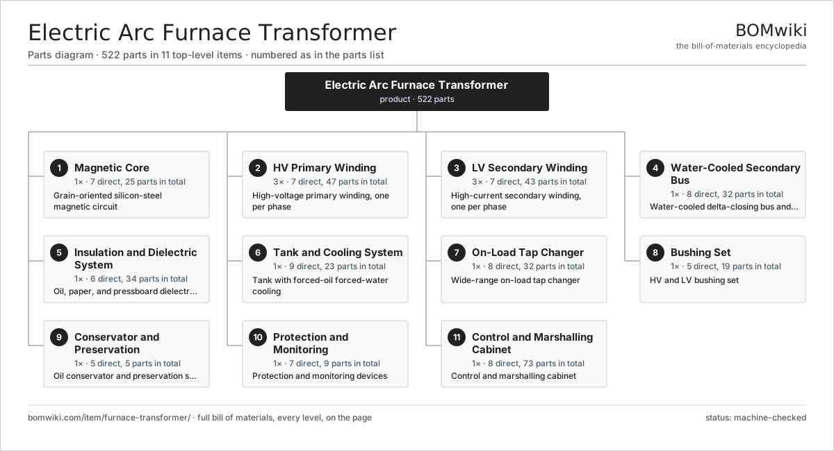
| # | Part | Qty | What it does |
|---|---|---|---|
| 1 | Magnetic Core 7 parts | 1× | Grain-oriented silicon-steel magnetic circuit |
| 2 | HV Primary Winding 7 parts | 3× | High-voltage primary winding, one per phase |
| 3 | LV Secondary Winding 7 parts | 3× | High-current secondary winding, one per phase |
| 4 | Water-Cooled Secondary Bus 8 parts | 1× | Water-cooled delta-closing bus and electrode terminals |
| 5 | Insulation and Dielectric System 6 parts | 1× | Oil, paper, and pressboard dielectric system |
| 6 | Tank and Cooling System 9 parts | 1× | Tank with forced-oil forced-water cooling |
| 7 | On-Load Tap Changer 8 parts | 1× | Wide-range on-load tap changer |
| 8 | Bushing Set 5 parts | 1× | HV and LV bushing set |
| 9 | Conservator and Preservation 5 parts | 1× | Oil conservator and preservation system |
| 10 | Protection and Monitoring 7 parts | 1× | Protection and monitoring devices |
| 11 | Control and Marshalling Cabinet 8 parts | 1× | Control and marshalling cabinet |
3D model
No 3D model yet. Have a CAD file of this? Add a 3D model. STL renders right on this page; STEP, FreeCAD, and OpenSCAD sources are welcome too (openly licensed, like all 3D models on BOMwiki).
Build & assembly graph
expand / collapse · shared sub-assemblies converge · links to related products · est. labourTap an assembly to expand/collapse · tap a part to open it · use “Open page” for any node · drag to pan, scroll to zoom.
Bill of materials for Electric Arc Furnace Transformer
11 top-level lines · 92 rows shown · 522 parts total · indented to 3 levels| # | Item / sub-assembly | Part no. | Qty/assy | Ext. qty | Parts | Type |
|---|---|---|---|---|---|---|
| 1 | Magnetic Core 7 parts | furnace-transformer-core | 1× | 1 | 25 | assembly |
| 1.1 | GO Silicon-Steel Lamination | furnace-transformer-core-lamination | 1× | 1 | · | part |
| 1.2 | Core Limb | furnace-transformer-core-limb | 3× | 3 | · | part |
| 1.3 | Core Yoke | furnace-transformer-core-yoke | 2× | 2 | · | part |
| 1.4 | Core Clamping Frame | furnace-transformer-core-clamp | 4× | 4 | · | part |
| 1.5 | Core Tie Rod | furnace-transformer-core-tie-rod | 8× | 8 | · | part |
| 1.6 | Core Ground Strap | furnace-transformer-core-ground-strap | 1× | 1 | · | part |
| 1.7 | Magnetic Flux Shunt | furnace-transformer-core-flux-shunt | 6× | 6 | · | part |
| 2 | HV Primary Winding 7 parts | furnace-transformer-hv-winding | 3× | 3 | 47 | assembly |
| 2.1 | HV Copper Conductor | furnace-transformer-hv-conductor | 1× | 3 | · | part |
| 2.2 | HV Disc Section | furnace-transformer-hv-disc | 1× | 3 | · | part |
| 2.3 | Regulating Winding | furnace-transformer-regulating-winding | 1× | 3 | · | part |
| 2.4 | Winding Support Cylinder | furnace-transformer-winding-cylinder | 1× | 3 | · | part |
| 2.5 | Radial Spacer Block | furnace-transformer-spacer-block | 40× | 120 | · | part |
| 2.6 | Winding End Ring | furnace-transformer-end-ring | 2× | 6 | · | part |
| 2.7 | HV Lead Exit | furnace-transformer-lead-exit | 1× | 3 | · | part |
| 3 | LV Secondary Winding 7 parts | furnace-transformer-lv-winding | 3× | 3 | 43 | assembly |
| 3.1 | LV Copper Sheet Turn | furnace-transformer-lv-foil | 1× | 3 | · | part |
| 3.2 | Water-Cooled LV Conductor | furnace-transformer-lv-tube-conductor | 1× | 3 | · | part |
| 3.3 | LV Cooling Duct | furnace-transformer-lv-cooling-duct | 8× | 24 | · | part |
| 3.4 | LV Clamp Ring | furnace-transformer-lv-clamp-ring | 2× | 6 | · | part |
| 3.5 | Flexible Copper Link | furnace-transformer-lv-flexible-link | 6× | 18 | · | part |
| 3.6 | Winding Support Cylinder | furnace-transformer-winding-cylinder | 1× | 3 | · | part |
| 3.7 | Radial Spacer Block | furnace-transformer-spacer-block | 24× | 72 | · | part |
| 4 | Water-Cooled Secondary Bus 8 parts | furnace-transformer-secondary-bus | 1× | 1 | 32 | assembly |
| 4.1 | Delta-Closing Bus | furnace-transformer-delta-bus | 1× | 1 | · | part |
| 4.2 | Water-Cooled Bus Bar | furnace-transformer-water-cooled-bus | 6× | 6 | · | part |
| 4.3 | Electrode Terminal Palm | furnace-transformer-electrode-terminal | 3× | 3 | · | part |
| 4.4 | Bus Post Insulator | furnace-transformer-bus-insulator | 6× | 6 | · | part |
| 4.5 | Cooling-Water Manifold | furnace-transformer-water-manifold | 1× | 1 | · | part |
| 4.6 | Insulating Water Hose | furnace-transformer-water-hose | 12× | 12 | · | part |
| 4.7 | Cooling-Water Flow Switch | furnace-transformer-flow-switch | 2× | 2 | · | part |
| 4.8 | Fastener Set | fastener-set | 1× | 1 | · | part |
| 5 | Insulation and Dielectric System 6 parts | furnace-transformer-insulation | 1× | 1 | 34 | assembly |
| 5.1 | Mineral Insulating Oil | furnace-transformer-mineral-oil | 1× | 1 | · | part |
| 5.2 | Kraft Paper Insulation | furnace-transformer-paper-insulation | 1× | 1 | · | part |
| 5.3 | Pressboard Barrier | furnace-transformer-pressboard-barrier | 12× | 12 | · | part |
| 5.4 | Pressboard Angle Ring | furnace-transformer-angle-ring | 8× | 8 | · | part |
| 5.5 | Lead Support Frame | furnace-transformer-lead-support | 6× | 6 | · | part |
| 5.6 | Static Ring | furnace-transformer-static-ring | 6× | 6 | · | part |
| 6 | Tank and Cooling System 9 parts | furnace-transformer-tank-cooling | 1× | 1 | 23 | assembly |
| 6.1 | Transformer Tank | furnace-transformer-tank | 1× | 1 | · | part |
| 6.2 | Tank Cover | furnace-transformer-tank-cover | 1× | 1 | · | part |
| 6.3 | Oil-to-Water Cooler | furnace-transformer-oil-water-cooler | 2× | 2 | · | part |
| 6.4 | Forced-Oil Pump | furnace-transformer-oil-pump | 2× | 2 | · | part |
| 6.5 | Cooling Radiator | furnace-transformer-radiator | 6× | 6 | · | part |
| 6.6 | Radiator Fan | furnace-transformer-cooling-fan | 8× | 8 | · | part |
| 6.7 | Oil Valve Set | furnace-transformer-valve-set | 1× | 1 | · | part |
| 6.8 | Transport Skid | furnace-transformer-skid | 1× | 1 | · | part |
| 6.9 | O-Ring Set | oring-set | 1× | 1 | · | part |
| 7 | On-Load Tap Changer 8 parts | furnace-transformer-oltc | 1× | 1 | 32 | assembly |
| 7.1 | Diverter Switch | furnace-transformer-oltc-diverter | 1× | 1 | · | part |
| 7.2 | Tap Selector | furnace-transformer-oltc-selector | 1× | 1 | · | part |
| 7.3 | OLTC Motor Drive Unit | furnace-transformer-oltc-drive | 1× | 1 | · | part |
| 7.4 | Transition Resistor | furnace-transformer-oltc-transition-resistor | 2× | 2 | · | part |
| 7.5 | Diverter Oil Compartment | furnace-transformer-oltc-oil-compartment | 1× | 1 | · | part |
| 7.6 | Helical Gear Pair | gear-pair | 1× | 1 | · | part |
| 7.7 | Servo Motor 4 parts | servo-motor | 1× | 1 | 24 | assembly |
| 7.7.1 | Stator Assembly 3 parts + deeper › | stator-assembly | 1× | 1 | 3 | assembly |
| 7.7.2 | Rotor Assembly 4 parts + deeper › | rotor-assembly | 1× | 1 | 19 | assembly |
| 7.7.3 | Encoder | encoder | 1× | 1 | · | part |
| 7.7.4 | Motor Housing | motor-housing | 1× | 1 | · | part |
| 7.8 | Tap Position Indicator | furnace-transformer-oltc-position-indicator | 1× | 1 | · | part |
| 8 | Bushing Set 5 parts | furnace-transformer-bushings | 1× | 1 | 19 | assembly |
| 8.1 | HV Condenser Bushing | furnace-transformer-hv-bushing | 3× | 3 | · | part |
| 8.2 | LV High-Current Bushing | furnace-transformer-lv-bushing | 6× | 6 | · | part |
| 8.3 | Neutral Bushing | furnace-transformer-neutral-bushing | 1× | 1 | · | part |
| 8.4 | Bushing Current Transformer | furnace-transformer-bushing-ct | 6× | 6 | · | part |
| 8.5 | Bushing Turret | furnace-transformer-bushing-turret | 3× | 3 | · | part |
| 9 | Conservator and Preservation 5 parts | furnace-transformer-conservator | 1× | 1 | 5 | assembly |
| 9.1 | Conservator Tank | furnace-transformer-conservator-tank | 1× | 1 | · | part |
| 9.2 | Conservator Air Cell | furnace-transformer-air-cell | 1× | 1 | · | part |
| 9.3 | Silica-Gel Breather | furnace-transformer-silica-breather | 1× | 1 | · | part |
| 9.4 | Magnetic Oil-Level Gauge | furnace-transformer-oil-level-gauge | 1× | 1 | · | part |
| 9.5 | Conservator Isolating Valve | furnace-transformer-conservator-valve | 1× | 1 | · | part |
| 10 | Protection and Monitoring 7 parts | furnace-transformer-protection | 1× | 1 | 9 | assembly |
| 10.1 | Buchholz Relay | furnace-transformer-buchholz | 1× | 1 | · | part |
| 10.2 | Pressure-Relief Device | furnace-transformer-pressure-relief | 1× | 1 | · | part |
| 10.3 | Sudden-Pressure Relay | furnace-transformer-sudden-pressure-relay | 1× | 1 | · | part |
| 10.4 | Winding Temperature Indicator | furnace-transformer-winding-temp | 2× | 2 | · | part |
| 10.5 | Top-Oil Temperature Indicator | furnace-transformer-oil-temp | 1× | 1 | · | part |
| 10.6 | Pressure Sensor | pressure-sensor | 2× | 2 | · | part |
| 10.7 | Online DGA Monitor | furnace-transformer-dga-monitor | 1× | 1 | · | part |
| 11 | Control and Marshalling Cabinet 8 parts | furnace-transformer-marshalling | 1× | 1 | 73 | assembly |
| 11.1 | Marshalling Enclosure | furnace-transformer-cabinet-enclosure | 1× | 1 | · | part |
| 11.2 | Cooling-Stage Controller | furnace-transformer-cooling-controller | 1× | 1 | · | part |
| 11.3 | Relay | relay | 12× | 12 | · | part |
| 11.4 | Field Terminal Block | furnace-transformer-terminal-block | 40× | 40 | · | part |
| 11.5 | Wire Bundle | wire-bundle | 1× | 1 | · | part |
| 11.6 | Connector | connector | 16× | 16 | · | part |
| 11.7 | LCD Panel | lcd-panel | 1× | 1 | · | part |
| 11.8 | Cabinet Space Heater | furnace-transformer-space-heater | 1× | 1 | · | part |
Related products
same domain, ranked by shared parts Combined Heat and Power Unit
522 parts · shares 17 with this page
Combined Heat and Power Unit
522 parts · shares 17 with this page
 Gas-Insulated Switchgear
281 parts · shares 17 with this page
Gas-Insulated Switchgear
281 parts · shares 17 with this page
 HVDC Converter Transformer
582 parts · shares 17 with this page
HVDC Converter Transformer
582 parts · shares 17 with this page
 SCR NOx Reduction Unit
569 parts · shares 17 with this page
SCR NOx Reduction Unit
569 parts · shares 17 with this page
 Autotransformer
7,784 parts · shares 16 with this page
Autotransformer
7,784 parts · shares 16 with this page
Sourcing: possible vendors
Browse the supplier directory → Prices, MOQ, and lead times are algorithmic estimates, not quotes, and not claims about these companies. Company mappings are curated by keyword; est. price band $5k–$50M. How estimates work| Vendor | HQ | Specialty | MOQ | Lead time |
|---|---|---|---|---|
| gevernova.com ↗ | Cambridge, US | Power generation | made to order | 20–40 wks |
| siemens-energy.com ↗ | Munich, DE | Power & grid | made to order | 20–40 wks |
| hitachienergy.com ↗ | Zurich, CH | Grid & transformers | made to order | 20–40 wks |
|
🇨🇭ABB
abb.com ↗
|
Zurich, CH | Electrification & automation | made to order | 20–40 wks |
| se.com ↗ | Rueil-Malmaison, FR | Electrical & automation | made to order | 20–40 wks |
1,013-word article