HV Circuit Breaker
ProductOverview
A high-voltage circuit breaker is the switch that protects a transmission network by interrupting fault current. In normal service it carries load current with negligible loss, but when a protection relay detects a short circuit it must part its contacts and extinguish an arc carrying tens of thousands of amps within two or three cycles, then withstand the full recovery voltage across the open gap. It is the single most safety-critical device in a substation, and a transmission system is rated by what its breakers can interrupt.
This breaker is a three-phase outdoor design with one pole unit per phase, a shared operating mechanism, a support frame, a control cabinet, and an SF6 gas system that maintains the interrupting medium. The line and bus connect through the terminal set.
The Interrupting Pole
Each pole unit is a sealed column carrying one phase. At its heart is the interrupter chamber, where the actual current breaking happens. In the closed state, load current flows through the fixed contact and the moving contact, held together by pressure springs for low resistance. On a trip, the moving contact is driven down, current commutates onto the arcing contacts, and an arc strikes between them.
The arc is quenched by a gas blast. As the contacts open, the puffer piston compresses SF6 and forces it through the PTFE nozzle axially along the arc. SF6 is an excellent quenching gas because it captures free electrons and recovers its dielectric strength almost instantly at the current zero. At that zero crossing, the gas flow cools the channel below the point where it can reignite, and the gap holds off the returning voltage. The arcing contacts are tungsten-copper so they erode in place of the precious main contacts, and the grading capacitor equalizes recovery voltage across the gap. The live parts sit on top of the insulator column, crowned by a corona shield that grades the field and prevents discharge into the air.
The Operating Mechanism
Breaking fault current demands fast, repeatable motion, which is the job of the operating mechanism. It uses stored spring energy because springs deliver consistent force regardless of supply voltage. A charged closing spring makes the breaker, while the opening springs drive the contacts apart on a trip. The energy path runs through the operating cam shaft to all three pole drive rods, and a hydraulic damper absorbs the kinetic energy at the end of travel so the mechanism does not destroy itself.
Control is electrical. A protection relay energizes the trip coil, which releases a latch and lets the opening spring fly. A duplicate trip coil gives redundancy for critical circuits. The closing coil releases the closing latch, and immediately afterward the charging motor re-cocks the closing spring through a gear train so the breaker is ready for the next operation. The auxiliary switch reports the contact position back to the control scheme and interlocks against improper operation.
Auto-Reclosing
Most transmission faults are transient: a lightning flashover or a branch that clears itself. The breaker is therefore specified for an auto-reclose duty cycle, typically open, wait 0.3 seconds, then close-open. The mechanism stores enough spring energy to perform this whole sequence, and the control board in the cabinet sequences it. If the fault is still present when the breaker recloses, it trips again and locks out, leaving the line dead until crews investigate.
Gas System and Monitoring
Interrupting performance depends entirely on gas density, so the SF6 gas system is continuously supervised. Each pole carries a gas density monitor, a pressure switch temperature-compensated so it reads true density rather than raw pressure. A first stage alarms on a slow leak; a second stage blocks operation entirely, because operating with low gas would risk a failed interruption and a destroyed breaker. Gas is filled and sampled through the fill valve, a rupture disc vents the pole safely if internal pressure runs away, and a desiccant cartridge keeps moisture out so the dielectric strength stays high.
Control, Frame, and Terminals
The control cabinet holds the local intelligence: the control board, an anti-pumping relay that prevents the breaker from repeatedly slamming onto a standing fault, a position indicator, and a heater that keeps condensation off the wiring. The whole apparatus stands on the galvanized support frame, with each pole raised on its own pole stand. High current enters and leaves through the terminal set, where flexible connectors absorb thermal expansion between the breaker and the rigid bus.
Variants and Use
The dominant variants are SF6 puffer breakers, used across the full voltage range, and vacuum breakers, which dominate at distribution and medium voltage and are now reaching 145 kV. Vacuum interrupters need no gas and almost no maintenance but are harder to scale to the highest voltages, where SF6 still leads. Environmental pressure to retire SF6, a potent greenhouse gas, is driving development of clean-air and fluoronitrile alternatives. Regardless of medium, the breaker is the device every transmission line, transformer, and bus coupler depends on to clear faults before they damage equipment or destabilize the grid.
HV Circuit Breaker parts and their functions
6 top-level parts · 243 parts in total · full bill of materials below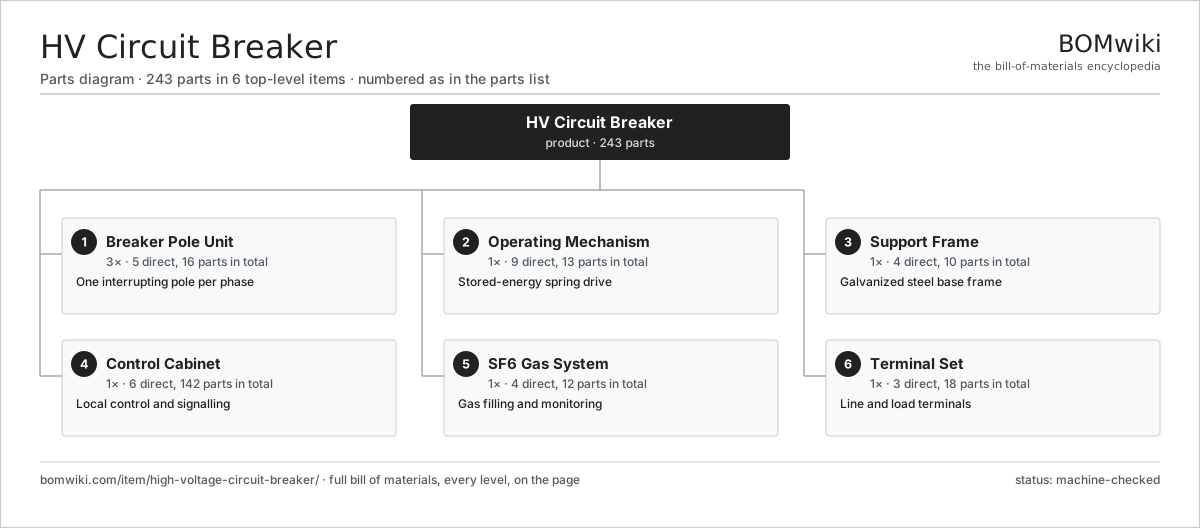
| # | Part | Qty | What it does |
|---|---|---|---|
| 1 | Breaker Pole Unit 5 parts | 3× | One interrupting pole per phase |
| 2 | Operating Mechanism 9 parts | 1× | Stored-energy spring drive |
| 3 | Support Frame 4 parts | 1× | Galvanized steel base frame |
| 4 | Control Cabinet 6 parts | 1× | Local control and signalling |
| 5 | SF6 Gas System 4 parts | 1× | Gas filling and monitoring |
| 6 | Terminal Set 3 parts | 1× | Line and load terminals |
3D model
No 3D model yet. Have a CAD file of this? Add a 3D model. STL renders right on this page; STEP, FreeCAD, and OpenSCAD sources are welcome too (openly licensed, like all 3D models on BOMwiki).
Build & assembly graph
expand / collapse · shared sub-assemblies converge · links to related products · est. labourTap an assembly to expand/collapse · tap a part to open it · use “Open page” for any node · drag to pan, scroll to zoom.
Bill of materials for HV Circuit Breaker
6 top-level lines · 49 rows shown · 243 parts total · indented to 3 levels| # | Item / sub-assembly | Part no. | Qty/assy | Ext. qty | Parts | Type |
|---|---|---|---|---|---|---|
| 1 | Breaker Pole Unit 5 parts | hvcb-pole-unit | 3× | 3 | 16 | assembly |
| 1.1 | Interrupter Chamber 7 parts | hvcb-interrupter | 1× | 3 | 12 | assembly |
| 1.1.1 | Fixed Contact | hvcb-fixed-contact | 1× | 3 | · | part |
| 1.1.2 | Moving Contact | hvcb-moving-contact | 1× | 3 | · | part |
| 1.1.3 | Arcing Contact Pair | hvcb-arcing-contact-pair | 1× | 3 | · | part |
| 1.1.4 | PTFE Nozzle | hvcb-ptfe-nozzle | 1× | 3 | · | part |
| 1.1.5 | Puffer Piston and Cylinder | hvcb-puffer-piston | 1× | 3 | · | part |
| 1.1.6 | Contact Pressure Spring | hvcb-contact-spring | 4× | 12 | · | part |
| 1.1.7 | O-Ring Set | oring-set | 3× | 9 | · | part |
| 1.2 | Insulator Column | hvcb-insulator-column | 1× | 3 | · | part |
| 1.3 | Grading Capacitor | hvcb-grading-capacitor | 1× | 3 | · | part |
| 1.4 | Corona Shield | hvcb-corona-shield | 1× | 3 | · | part |
| 1.5 | Pole Base Housing | hvcb-pole-base | 1× | 3 | · | part |
| 2 | Operating Mechanism 9 parts | hvcb-operating-mechanism | 1× | 1 | 13 | assembly |
| 2.1 | Closing Spring | hvcb-closing-spring | 1× | 1 | · | part |
| 2.2 | Opening Spring | hvcb-opening-spring | 3× | 3 | · | part |
| 2.3 | Spring Charging Motor | hvcb-charging-motor | 1× | 1 | · | part |
| 2.4 | Trip Coil | hvcb-trip-coil | 2× | 2 | · | part |
| 2.5 | Closing Coil | hvcb-closing-coil | 1× | 1 | · | part |
| 2.6 | Operating Cam Shaft | hvcb-cam-shaft | 1× | 1 | · | part |
| 2.7 | Hydraulic Damper | hvcb-damper | 2× | 2 | · | part |
| 2.8 | Auxiliary Switch | hvcb-aux-switch | 1× | 1 | · | part |
| 2.9 | Helical Gear Pair | gear-pair | 1× | 1 | · | part |
| 3 | Support Frame 4 parts | hvcb-support-frame | 1× | 1 | 10 | assembly |
| 3.1 | Base Frame | hvcb-base-frame | 1× | 1 | · | part |
| 3.2 | Pole Support Stand | hvcb-pole-stand | 3× | 3 | · | part |
| 3.3 | Fastener Set | fastener-set | 2× | 2 | · | part |
| 3.4 | Lifting Lug | hvcb-lifting-lug | 4× | 4 | · | part |
| 4 | Control Cabinet 6 parts | hvcb-control-cabinet | 1× | 1 | 142 | assembly |
| 4.1 | Control and Supervision Board 5 parts | hvcb-control-board | 1× | 1 | 136 | assembly |
| 4.1.1 | Bare PCB | pcb-bare | 1× | 1 | · | part |
| 4.1.2 | Microcontroller | mcu | 1× | 1 | · | part |
| 4.1.3 | Relay | relay | 6× | 6 | · | part |
| 4.1.4 | SMD Passive (R/C/L) | smd-passives | 120× | 120 | · | part |
| 4.1.5 | Connector | connector | 8× | 8 | · | part |
| 4.2 | Anti-Pumping Relay | hvcb-anti-pump-relay | 1× | 1 | · | part |
| 4.3 | Position Indicator | hvcb-position-indicator | 1× | 1 | · | part |
| 4.4 | Cabinet Heater | hvcb-cabinet-heater | 1× | 1 | · | part |
| 4.5 | Terminal Block Set | hvcb-terminal-block | 1× | 1 | · | part |
| 4.6 | Wire Bundle | wire-bundle | 2× | 2 | · | part |
| 5 | SF6 Gas System 4 parts | hvcb-sf6-gas-system | 1× | 1 | 12 | assembly |
| 5.1 | Gas Density Monitor | hvcb-density-monitor | 3× | 3 | · | part |
| 5.2 | Gas Fill Valve | hvcb-fill-valve | 3× | 3 | · | part |
| 5.3 | Rupture Disc | hvcb-rupture-disc | 3× | 3 | · | part |
| 5.4 | Desiccant Cartridge | hvcb-desiccant-cartridge | 3× | 3 | · | part |
| 6 | Terminal Set 3 parts | hvcb-terminal-set | 1× | 1 | 18 | assembly |
| 6.1 | Terminal Pad | hvcb-terminal-pad | 6× | 6 | · | part |
| 6.2 | Flexible Connector | hvcb-flexible-connector | 6× | 6 | · | part |
| 6.3 | Corona Shield | hvcb-corona-shield | 6× | 6 | · | part |
Related products
same domain, ranked by shared parts Air-Insulated Substation Bay
1,329 parts · shares 3 with this page
Air-Insulated Substation Bay
1,329 parts · shares 3 with this page
 Autotransformer
7,784 parts · shares 3 with this page
Bottom Ash Handling System
1,782 parts · shares 3 with this page
Autotransformer
7,784 parts · shares 3 with this page
Bottom Ash Handling System
1,782 parts · shares 3 with this page
 Combined Heat and Power Unit
522 parts · shares 3 with this page
Combined Heat and Power Unit
522 parts · shares 3 with this page
 Cooling Tower Cell
219 parts · shares 3 with this page
Cooling Tower Cell
219 parts · shares 3 with this page
 Electric Arc Furnace Transformer
522 parts · shares 3 with this page
Electric Arc Furnace Transformer
522 parts · shares 3 with this page
Sourcing: possible vendors
Browse the supplier directory → Prices, MOQ, and lead times are algorithmic estimates, not quotes, and not claims about these companies. Company mappings are curated by keyword; est. price band $5k–$50M. How estimates work| Vendor | HQ | Specialty | MOQ | Lead time |
|---|---|---|---|---|
| gevernova.com ↗ | Cambridge, US | Power generation | made to order | 20–40 wks |
| siemens-energy.com ↗ | Munich, DE | Power & grid | made to order | 20–40 wks |
| hitachienergy.com ↗ | Zurich, CH | Grid & transformers | made to order | 20–40 wks |
|
🇨🇭ABB
abb.com ↗
|
Zurich, CH | Electrification & automation | made to order | 20–40 wks |
| se.com ↗ | Rueil-Malmaison, FR | Electrical & automation | made to order | 20–40 wks |
977-word article