Landfill Gas Flare
ProductOverview
A landfill gas flare burns the methane that a closed or active landfill gives off as buried waste decomposes. That gas is roughly half methane and half carbon dioxide, with traces of other compounds, and methane is a strong greenhouse gas, so it cannot simply be vented. The flare collects the gas from the well field and burns it at a controlled high temperature, converting the methane to carbon dioxide and water and destroying the trace odor and hazardous compounds along with it. Where the gas is not used to make power, a flare is the required control device, and even sites with engines keep a flare to handle excess gas and to run while engines are down.
Gas is drawn in and burned at the Flare Stack and Burner. Before it gets there it passes the safety Gas Train Skid, it is lit by the Ignition System, the whole sequence is run by the Control Panel, the Booster Blower supplies the draw, and the Instrumentation sensors report how cleanly it is running.
The stack and burner
The Flare Stack and Burner is where combustion happens. In an enclosed flare it is a tall steel Stack Shell lined with Refractory Lining that holds the heat in, so the gas stays above the destruction temperature long enough to burn completely and the flame is hidden from view. Gas enters through the Burner Head, whose Burner Ring manifold feeds many Gas Nozzle jets that mix the gas with air drawn through an adjustable Air Damper. A Wind Shield keeps gusts from blowing the flame off the burner, and a Base Ring anchors the stack to its foundation. The two main forms are this enclosed flare, which controls temperature and residence time for high methane destruction and hides the flame, and the simpler open candlestick flare, used as backup or on smaller sites.
Gas train and safety
Landfill gas is wet, low-pressure, and explosive, so the Gas Train Skid conditions and guards it before it reaches the flame. A Condensate Knockout drops out the liquid the wet gas carries, a Flow Control Valve valve sets the gas rate to hold the target combustion temperature, and two Shutoff Valve valves close automatically and fail safe on any fault. The most important safety item is the Flame Arrestor, which lets gas pass toward the burner but stops a flame from travelling back down the line into the collection piping and wells. All of this is assembled on a Skid Frame with its Skid Piping as one unit that ships and installs together.
Ignition and flame proving
The flare cannot rely on the gas staying lit by itself, so the Ignition System both starts the flame and continuously proves it. A small Pilot Burner, usually on propane fed by a Pilot Gas Valve, is lit by a Spark Igniter electrode driven from an Ignition Transformer. Once the pilot is proven the main gas is admitted and lights from it. A Flame Sensor sensor watches the flame at all times; if it goes out, the Control Panel closes the gas at once so unburned methane is never released. This prove-then-admit sequence, and the trip on flame loss, are what make an automatic flare safe to run unattended.
Control, blower, and instruments
The Control Panel panel runs everything. A PLC with its Microcontroller and Bare PCB sequences the purge, ignition, and run phases, a certified Flame Safety Relay handles the flame safety independently, and an operator reads status on the Operator HMI. The panel runs on a Power Supply and drives Relay outputs through a Wire Bundle inside a rated Panel Enclosure. Because the gas leaves the wells at only a few inches of water column, the Booster Blower is needed to lift it to burner pressure: an explosion-rated Blower Motor turns an Impeller in a sealed Blower Housing on Ball Bearing supports with Oil Seal shaft seals. The Instrumentation sensors close the loop: Thermocouple probes read combustion temperature, a Flow Meter logs how much gas is burned, Pressure Sensor units watch line pressure, and a Methane Analyzer reports methane content so the burn can be tuned.
Use and variants
Flares are installed at municipal landfills, closed dumps, and waste-to-energy sites as the primary or backup control for collected gas. The enclosed flare is chosen where regulators require proven high methane destruction, measured residence time, and a hidden flame, while open candlestick flares serve as emergency backup, on small sites, or to burn excess when engines cannot take all the gas. Sizing follows the well-field gas rate, which falls over the years as the waste finishes decomposing, so flares are specified with a wide turndown so they keep burning cleanly as the flow drops. Paired with a Landfill Gas Blower Skid that extracts the gas, the flare completes the gas-management system that keeps a landfill from venting methane to the air.
Landfill Gas Flare parts and their functions
6 top-level parts · 60 parts in total · full bill of materials below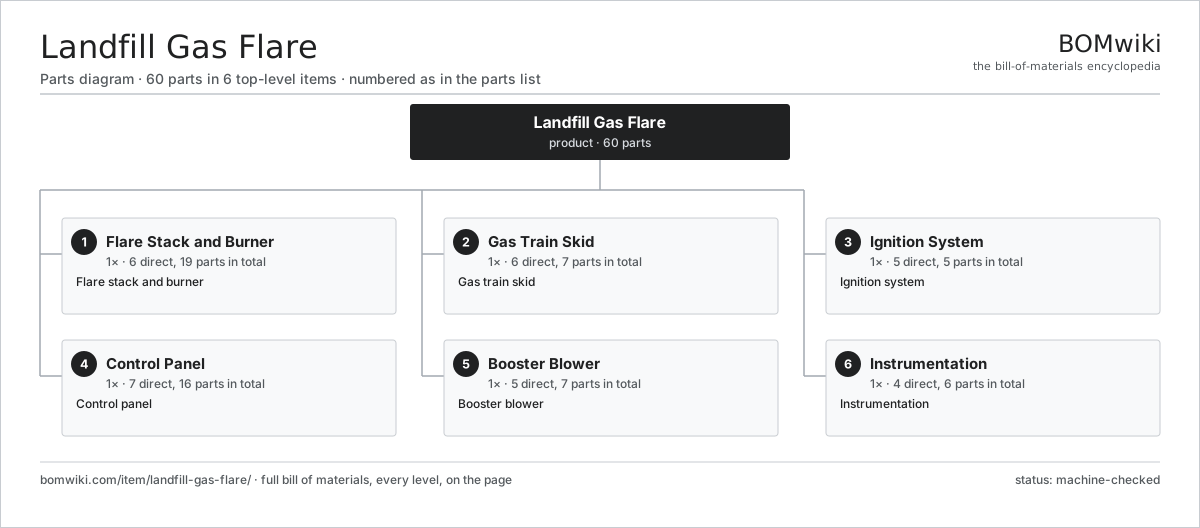
| # | Part | Qty | What it does |
|---|---|---|---|
| 1 | Flare Stack and Burner 6 parts | 1× | Flare stack and burner |
| 2 | Gas Train Skid 6 parts | 1× | Gas train skid |
| 3 | Ignition System 5 parts | 1× | Ignition system |
| 4 | Control Panel 7 parts | 1× | Control panel |
| 5 | Booster Blower 5 parts | 1× | Booster blower |
| 6 | Instrumentation 4 parts | 1× | Instrumentation |
3D model
No 3D model yet. Have a CAD file of this? Add a 3D model. STL renders right on this page; STEP, FreeCAD, and OpenSCAD sources are welcome too (openly licensed, like all 3D models on BOMwiki).
Build & assembly graph
expand / collapse · shared sub-assemblies converge · links to related products · est. labourTap an assembly to expand/collapse · tap a part to open it · use “Open page” for any node · drag to pan, scroll to zoom.
Bill of materials for Landfill Gas Flare
6 top-level lines · 46 rows shown · 60 parts total · indented to 3 levels| # | Item / sub-assembly | Part no. | Qty/assy | Ext. qty | Parts | Type |
|---|---|---|---|---|---|---|
| 1 | Flare Stack and Burner 6 parts | landfill-gas-flare-stack | 1× | 1 | 19 | assembly |
| 1.1 | Stack Shell | landfill-gas-flare-shell | 1× | 1 | · | part |
| 1.2 | Refractory Lining | landfill-gas-flare-refractory | 1× | 1 | · | part |
| 1.3 | Burner Head 3 parts | landfill-gas-flare-burner | 1× | 1 | 14 | assembly |
| 1.3.1 | Burner Ring | landfill-gas-flare-burner-ring | 1× | 1 | · | part |
| 1.3.2 | Gas Nozzle | landfill-gas-flare-nozzle | 12× | 12 | · | part |
| 1.3.3 | Pilot Tube | landfill-gas-flare-pilot-tube | 1× | 1 | · | part |
| 1.4 | Air Damper | landfill-gas-flare-air-damper | 1× | 1 | · | part |
| 1.5 | Wind Shield | landfill-gas-flare-windshield | 1× | 1 | · | part |
| 1.6 | Base Ring | landfill-gas-flare-base-ring | 1× | 1 | · | part |
| 2 | Gas Train Skid 6 parts | landfill-gas-flare-skid | 1× | 1 | 7 | assembly |
| 2.1 | Flame Arrestor | landfill-gas-flare-flame-arrestor | 1× | 1 | · | part |
| 2.2 | Shutoff Valve | landfill-gas-flare-shutoff-valve | 2× | 2 | · | part |
| 2.3 | Flow Control Valve | landfill-gas-flare-flow-control | 1× | 1 | · | part |
| 2.4 | Condensate Knockout | landfill-gas-flare-knockout | 1× | 1 | · | part |
| 2.5 | Skid Frame | landfill-gas-flare-skid-frame | 1× | 1 | · | part |
| 2.6 | Skid Piping | landfill-gas-flare-piping | 1× | 1 | · | part |
| 3 | Ignition System 5 parts | landfill-gas-flare-ignition | 1× | 1 | 5 | assembly |
| 3.1 | Pilot Burner | landfill-gas-flare-pilot-burner | 1× | 1 | · | part |
| 3.2 | Spark Igniter | landfill-gas-flare-igniter | 1× | 1 | · | part |
| 3.3 | Flame Sensor | landfill-gas-flare-flame-rod | 1× | 1 | · | part |
| 3.4 | Ignition Transformer | landfill-gas-flare-ignition-transformer | 1× | 1 | · | part |
| 3.5 | Pilot Gas Valve | landfill-gas-flare-pilot-gas-valve | 1× | 1 | · | part |
| 4 | Control Panel 7 parts | landfill-gas-flare-control | 1× | 1 | 16 | assembly |
| 4.1 | PLC 4 parts | landfill-gas-flare-plc | 1× | 1 | 7 | assembly |
| 4.1.1 | Bare PCB | pcb-bare | 1× | 1 | · | part |
| 4.1.2 | Microcontroller | mcu | 1× | 1 | · | part |
| 4.1.3 | SMD Passive (R/C/L) | smd-passives | 1× | 1 | · | part |
| 4.1.4 | Connector | connector | 4× | 4 | · | part |
| 4.2 | Flame Safety Relay | landfill-gas-flare-flame-relay | 1× | 1 | · | part |
| 4.3 | Power Supply | power-supply | 1× | 1 | · | part |
| 4.4 | Operator HMI | landfill-gas-flare-hmi | 1× | 1 | · | part |
| 4.5 | Relay | relay | 4× | 4 | · | part |
| 4.6 | Panel Enclosure | landfill-gas-flare-panel-enclosure | 1× | 1 | · | part |
| 4.7 | Wire Bundle | wire-bundle | 1× | 1 | · | part |
| 5 | Booster Blower 5 parts | landfill-gas-flare-blower | 1× | 1 | 7 | assembly |
| 5.1 | Blower Motor | landfill-gas-flare-blower-motor | 1× | 1 | · | part |
| 5.2 | Impeller | landfill-gas-flare-impeller | 1× | 1 | · | part |
| 5.3 | Blower Housing | landfill-gas-flare-blower-housing | 1× | 1 | · | part |
| 5.4 | Ball Bearing | ball-bearing | 2× | 2 | · | part |
| 5.5 | Oil Seal | oil-seal | 2× | 2 | · | part |
| 6 | Instrumentation 4 parts | landfill-gas-flare-instrument | 1× | 1 | 6 | assembly |
| 6.1 | Thermocouple | landfill-gas-flare-thermocouple | 2× | 2 | · | part |
| 6.2 | Flow Meter | landfill-gas-flare-flow-meter | 1× | 1 | · | part |
| 6.3 | Methane Analyzer | landfill-gas-flare-gas-analyzer | 1× | 1 | · | part |
| 6.4 | Pressure Sensor | pressure-sensor | 2× | 2 | · | part |
Related products
same domain, ranked by shared parts Coal Pulverizer Mill
313 parts · shares 5 with this page
Coal Pulverizer Mill
313 parts · shares 5 with this page
 Combined Heat and Power Unit
522 parts · shares 5 with this page
Containerized Diesel Genset
655 parts · shares 5 with this page
Combined Heat and Power Unit
522 parts · shares 5 with this page
Containerized Diesel Genset
655 parts · shares 5 with this page
 Electrostatic Precipitator
879 parts · shares 5 with this page
Electrostatic Precipitator
879 parts · shares 5 with this page
 Flue Gas Desulfurization Scrubber
531 parts · shares 5 with this page
Flue Gas Desulfurization Scrubber
531 parts · shares 5 with this page
Sourcing: possible vendors
Browse the supplier directory → Prices, MOQ, and lead times are algorithmic estimates, not quotes, and not claims about these companies. Company mappings are curated by keyword; est. price band $5k–$50M. How estimates work| Vendor | HQ | Specialty | MOQ | Lead time |
|---|---|---|---|---|
| gevernova.com ↗ | Cambridge, US | Power generation | made to order | 20–40 wks |
| siemens-energy.com ↗ | Munich, DE | Power & grid | made to order | 20–40 wks |
| hitachienergy.com ↗ | Zurich, CH | Grid & transformers | made to order | 20–40 wks |
|
🇨🇭ABB
abb.com ↗
|
Zurich, CH | Electrification & automation | made to order | 20–40 wks |
| se.com ↗ | Rueil-Malmaison, FR | Electrical & automation | made to order | 20–40 wks |
920-word article