Heat Recovery Steam Generator
ProductOverview
A heat recovery steam generator captures the thermal energy in a gas turbine's exhaust and uses it to raise steam for a steam turbine. In a combined cycle, the gas turbine produces roughly two thirds of the plant output and exhausts gas at 600-640 C. Left to a simple-cycle stack, that heat is lost. The HRSG passes the exhaust over banks of water and steam tubes, dropping the gas temperature to about 80-100 C while generating high-pressure steam. The recovered steam drives a steam turbine that adds the final third of plant output, lifting overall efficiency from about 38 percent for the gas turbine alone to roughly 60 percent for the combined cycle.
The unit described here is a triple-pressure reheat design, the standard arrangement behind a modern F-class gas turbine. It has three independent steam circuits operating at different pressures, HP Steam Circuit, IP Steam Circuit, and LP Steam Circuit. Splitting heat recovery across three pressures lets the boiler match the falling gas temperature more closely along its length, which extracts more energy than a single-pressure boiler could.
Gas path and heat recovery
Exhaust enters through the Inlet Duct, a transition piece that spreads the turbine diffuser flow evenly across the first tube bank. Uneven distribution would overheat some tubes and starve others, so flow correction devices are often fitted here. Gas then crosses the tube banks in descending temperature order: the HP superheater and reheater face the hottest gas, followed by the HP evaporator, then the economizers, and finally the LP sections that recover the lowest-grade heat. Because the gas gives up heat as it travels, each bank sees cooler gas than the one before it, which fixes the order of the banks along the casing.
The single most important design number is the pinch point, the smallest temperature difference between the gas leaving the evaporator and the saturation temperature of the water inside it. A typical HP pinch is 8-12 C. A tighter pinch recovers more steam but needs far more tube surface, so it trades capital cost against output. Approach subcooling, usually 5-10 C, is the margin by which economizer outlet water stays below saturation to prevent steaming in the HP Economizer Bank tubes.
HP circuit
The HP circuit carries the highest energy flow. Feedwater is pumped to 120-170 bar by the HP Feedwater Pump, a multistage barrel pump, then heated near to saturation in the HP economizer. It enters the HP Steam Drum, where natural circulation drives water down the Downcomer Pipe pipes, through the HP Evaporator, and back up the Riser Pipe pipes as a steam-water mixture. The drum internals separate dry steam from water. Saturated steam then passes to the HP Superheater, which raises it to 565-600 C. Final temperature is trimmed by the HP Attemperator, which sprays feedwater into the steam between superheater stages. HP steam output runs 250-320 t/h for a large machine, and the steam leaves through the HP Main Steam Stop Valve to the HP turbine.
IP circuit and reheat
The IP circuit generates steam at 25-40 bar. Its main purpose is to feed the Reheater. Steam exhausted from the HP turbine, called cold reheat, returns to the HRSG and mixes with superheated IP steam, and the combined flow is reheated to 565-600 C before going to the IP turbine. Reheating lifts cycle efficiency and keeps moisture low in the last turbine stages. The Reheat Attemperator controls hot reheat temperature. The reheater and final superheater use Stainless Superheater Tube in their hottest rows because metal temperatures there exceed what Low-Alloy Superheater Tube can tolerate over a 100,000 hour design life.
LP circuit and feedwater
The LP circuit at 4-6 bar sits in the coldest gas, where the LP Economizer / Preheater acts as the feedwater preheater and brings stack gas down to 80-100 C. The LP evaporator commonly supplies steam to the Deaerator, which strips dissolved oxygen and carbon dioxide from condensate to protect the steel pressure parts from corrosion. The Feedwater System system distributes deaerated water to all three circuits, with pump minimum flow protected by the Recirculation Valve at low load. Each circuit holds drum level through its own feedwater control valve.
Structure, casing and chemistry
The pressure parts are built as harp-shaped tube modules hung from Roof Beam members so they grow downward freely as they heat. The Structural Steel and Supports carries this load through main columns to the foundation, and Coil Spring hangers absorb the vertical thermal travel. The Casing, Ducting and Stack forms a gas-tight insulated enclosure, with fabric Expansion Joint sections taking up differential expansion and a Diverter / Stack Damper that can route exhaust straight to the stack for simple-cycle running. Water chemistry is held by the Blowdown System system, which bleeds concentrated drum water to keep dissolved solids in range. The Instrumentation and Controls coordinate level, temperature, and pressure across the circuits and manage startup, where thick-walled components such as the HP drum limit how fast the unit can be brought up without thermal stress.
Operating considerations
Combined-cycle plants now cycle daily to follow demand, so startup time and thermal fatigue dominate HRSG design. Drum wall thickness sets the safe ramp rate, since the inner and outer surfaces heat at different speeds and the temperature gradient creates stress. Fast-start designs use thinner drums or once-through HP sections to cut startup from hours to under an hour. Attemperator spray must avoid wetting downstream tubes during transients, and the Drum Safety Valve set on each drum provides overpressure protection sized to the maximum steaming rate. Tube failures, when they occur, usually trace to flow-induced vibration, thermal fatigue at header welds, or under-deposit corrosion from poor water chemistry, which is why conductivity is monitored continuously and blowdown is adjusted to hold limits.
Heat Recovery Steam Generator parts and their functions
9 top-level parts · 2,622 parts in total · full bill of materials below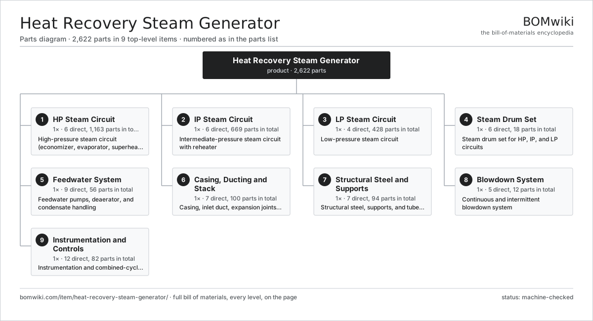
| # | Part | Qty | What it does |
|---|---|---|---|
| 1 | HP Steam Circuit 6 parts | 1× | High-pressure steam circuit (economizer, evaporator, superheater) |
| 2 | IP Steam Circuit 6 parts | 1× | Intermediate-pressure steam circuit with reheater |
| 3 | LP Steam Circuit 4 parts | 1× | Low-pressure steam circuit |
| 4 | Steam Drum Set 6 parts | 1× | Steam drum set for HP, IP, and LP circuits |
| 5 | Feedwater System 9 parts | 1× | Feedwater pumps, deaerator, and condensate handling |
| 6 | Casing, Ducting and Stack 7 parts | 1× | Casing, inlet duct, expansion joints, and stack |
| 7 | Structural Steel and Supports 7 parts | 1× | Structural steel, supports, and tube hangers |
| 8 | Blowdown System 5 parts | 1× | Continuous and intermittent blowdown system |
| 9 | Instrumentation and Controls 12 parts | 1× | Instrumentation and combined-cycle control interface |
3D model
No 3D model yet. Have a CAD file of this? Add a 3D model. STL renders right on this page; STEP, FreeCAD, and OpenSCAD sources are welcome too (openly licensed, like all 3D models on BOMwiki).
Build & assembly graph
expand / collapse · shared sub-assemblies converge · links to related products · est. labourTap an assembly to expand/collapse · tap a part to open it · use “Open page” for any node · drag to pan, scroll to zoom.
Bill of materials for Heat Recovery Steam Generator
9 top-level lines · 126 rows shown · 2,622 parts total · indented to 3 levels| # | Item / sub-assembly | Part no. | Qty/assy | Ext. qty | Parts | Type |
|---|---|---|---|---|---|---|
| 1 | HP Steam Circuit 6 parts | heat-recovery-steam-generator-hp-circuit | 1× | 1 | 1,163 | assembly |
| 1.1 | HP Economizer Bank 5 parts | heat-recovery-steam-generator-hp-economizer | 2× | 2 | 254 | assembly |
| 1.1.1 | Finned Tube | heat-recovery-steam-generator-finned-tube | 240× | 480 | · | part |
| 1.1.2 | Inlet Header | heat-recovery-steam-generator-inlet-header | 1× | 2 | · | part |
| 1.1.3 | Outlet Header | heat-recovery-steam-generator-outlet-header | 1× | 2 | · | part |
| 1.1.4 | Tube Support | heat-recovery-steam-generator-tube-support | 8× | 16 | · | part |
| 1.1.5 | Fastener Set | fastener-set | 4× | 8 | · | part |
| 1.2 | HP Evaporator 6 parts | heat-recovery-steam-generator-hp-evaporator | 1× | 1 | 342 | assembly |
| 1.2.1 | Bare Boiler Tube | heat-recovery-steam-generator-bare-tube | 320× | 320 | · | part |
| 1.2.2 | Downcomer Pipe | heat-recovery-steam-generator-downcomer | 4× | 4 | · | part |
| 1.2.3 | Riser Pipe | heat-recovery-steam-generator-riser | 6× | 6 | · | part |
| 1.2.4 | Inlet Header | heat-recovery-steam-generator-inlet-header | 1× | 1 | · | part |
| 1.2.5 | Outlet Header | heat-recovery-steam-generator-outlet-header | 1× | 1 | · | part |
| 1.2.6 | Tube Support | heat-recovery-steam-generator-tube-support | 10× | 10 | · | part |
| 1.3 | HP Superheater 5 parts | heat-recovery-steam-generator-hp-superheater | 1× | 1 | 310 | assembly |
| 1.3.1 | Low-Alloy Superheater Tube | heat-recovery-steam-generator-sh-tube-low-alloy | 180× | 180 | · | part |
| 1.3.2 | Stainless Superheater Tube | heat-recovery-steam-generator-sh-tube-stainless | 120× | 120 | · | part |
| 1.3.3 | Inlet Header | heat-recovery-steam-generator-inlet-header | 1× | 1 | · | part |
| 1.3.4 | Outlet Header | heat-recovery-steam-generator-outlet-header | 1× | 1 | · | part |
| 1.3.5 | Tube Support | heat-recovery-steam-generator-tube-support | 8× | 8 | · | part |
| 1.4 | HP Attemperator | heat-recovery-steam-generator-hp-attemperator | 1× | 1 | · | part |
| 1.5 | HP Feedwater Control Valve | heat-recovery-steam-generator-hp-feed-control-valve | 1× | 1 | · | part |
| 1.6 | HP Main Steam Stop Valve | heat-recovery-steam-generator-hp-stop-valve | 1× | 1 | · | part |
| 2 | IP Steam Circuit 6 parts | heat-recovery-steam-generator-ip-circuit | 1× | 1 | 669 | assembly |
| 2.1 | IP Economizer 4 parts | heat-recovery-steam-generator-ip-economizer | 1× | 1 | 128 | assembly |
| 2.1.1 | Finned Tube | heat-recovery-steam-generator-finned-tube | 120× | 120 | · | part |
| 2.1.2 | Inlet Header | heat-recovery-steam-generator-inlet-header | 1× | 1 | · | part |
| 2.1.3 | Outlet Header | heat-recovery-steam-generator-outlet-header | 1× | 1 | · | part |
| 2.1.4 | Tube Support | heat-recovery-steam-generator-tube-support | 6× | 6 | · | part |
| 2.2 | IP Evaporator 6 parts | heat-recovery-steam-generator-ip-evaporator | 1× | 1 | 215 | assembly |
| 2.2.1 | Bare Boiler Tube | heat-recovery-steam-generator-bare-tube | 200× | 200 | · | part |
| 2.2.2 | Downcomer Pipe | heat-recovery-steam-generator-downcomer | 3× | 3 | · | part |
| 2.2.3 | Riser Pipe | heat-recovery-steam-generator-riser | 4× | 4 | · | part |
| 2.2.4 | Inlet Header | heat-recovery-steam-generator-inlet-header | 1× | 1 | · | part |
| 2.2.5 | Outlet Header | heat-recovery-steam-generator-outlet-header | 1× | 1 | · | part |
| 2.2.6 | Tube Support | heat-recovery-steam-generator-tube-support | 6× | 6 | · | part |
| 2.3 | IP Superheater 4 parts | heat-recovery-steam-generator-ip-superheater | 1× | 1 | 96 | assembly |
| 2.3.1 | Low-Alloy Superheater Tube | heat-recovery-steam-generator-sh-tube-low-alloy | 90× | 90 | · | part |
| 2.3.2 | Inlet Header | heat-recovery-steam-generator-inlet-header | 1× | 1 | · | part |
| 2.3.3 | Outlet Header | heat-recovery-steam-generator-outlet-header | 1× | 1 | · | part |
| 2.3.4 | Tube Support | heat-recovery-steam-generator-tube-support | 4× | 4 | · | part |
| 2.4 | Reheater 5 parts | heat-recovery-steam-generator-reheater | 1× | 1 | 228 | assembly |
| 2.4.1 | Low-Alloy Superheater Tube | heat-recovery-steam-generator-sh-tube-low-alloy | 140× | 140 | · | part |
| 2.4.2 | Stainless Superheater Tube | heat-recovery-steam-generator-sh-tube-stainless | 80× | 80 | · | part |
| 2.4.3 | Inlet Header | heat-recovery-steam-generator-inlet-header | 1× | 1 | · | part |
| 2.4.4 | Outlet Header | heat-recovery-steam-generator-outlet-header | 1× | 1 | · | part |
| 2.4.5 | Tube Support | heat-recovery-steam-generator-tube-support | 6× | 6 | · | part |
| 2.5 | Reheat Attemperator | heat-recovery-steam-generator-reheat-attemperator | 1× | 1 | · | part |
| 2.6 | IP Feedwater Control Valve | heat-recovery-steam-generator-ip-feed-control-valve | 1× | 1 | · | part |
| 3 | LP Steam Circuit 4 parts | heat-recovery-steam-generator-lp-circuit | 1× | 1 | 428 | assembly |
| 3.1 | LP Economizer / Preheater 4 parts | heat-recovery-steam-generator-lp-economizer | 1× | 1 | 168 | assembly |
| 3.1.1 | Finned Tube | heat-recovery-steam-generator-finned-tube | 160× | 160 | · | part |
| 3.1.2 | Inlet Header | heat-recovery-steam-generator-inlet-header | 1× | 1 | · | part |
| 3.1.3 | Outlet Header | heat-recovery-steam-generator-outlet-header | 1× | 1 | · | part |
| 3.1.4 | Tube Support | heat-recovery-steam-generator-tube-support | 6× | 6 | · | part |
| 3.2 | LP Evaporator 6 parts | heat-recovery-steam-generator-lp-evaporator | 1× | 1 | 194 | assembly |
| 3.2.1 | Bare Boiler Tube | heat-recovery-steam-generator-bare-tube | 180× | 180 | · | part |
| 3.2.2 | Downcomer Pipe | heat-recovery-steam-generator-downcomer | 3× | 3 | · | part |
| 3.2.3 | Riser Pipe | heat-recovery-steam-generator-riser | 4× | 4 | · | part |
| 3.2.4 | Inlet Header | heat-recovery-steam-generator-inlet-header | 1× | 1 | · | part |
| 3.2.5 | Outlet Header | heat-recovery-steam-generator-outlet-header | 1× | 1 | · | part |
| 3.2.6 | Tube Support | heat-recovery-steam-generator-tube-support | 5× | 5 | · | part |
| 3.3 | LP Superheater 4 parts | heat-recovery-steam-generator-lp-superheater | 1× | 1 | 65 | assembly |
| 3.3.1 | Low-Alloy Superheater Tube | heat-recovery-steam-generator-sh-tube-low-alloy | 60× | 60 | · | part |
| 3.3.2 | Inlet Header | heat-recovery-steam-generator-inlet-header | 1× | 1 | · | part |
| 3.3.3 | Outlet Header | heat-recovery-steam-generator-outlet-header | 1× | 1 | · | part |
| 3.3.4 | Tube Support | heat-recovery-steam-generator-tube-support | 3× | 3 | · | part |
| 3.4 | LP Feedwater Control Valve | heat-recovery-steam-generator-lp-feed-control-valve | 1× | 1 | · | part |
| 4 | Steam Drum Set 6 parts | heat-recovery-steam-generator-drums | 1× | 1 | 18 | assembly |
| 4.1 | HP Steam Drum | heat-recovery-steam-generator-hp-drum | 1× | 1 | · | part |
| 4.2 | IP Steam Drum | heat-recovery-steam-generator-ip-drum | 1× | 1 | · | part |
| 4.3 | LP Steam Drum | heat-recovery-steam-generator-lp-drum | 1× | 1 | · | part |
| 4.4 | Drum Internals | heat-recovery-steam-generator-drum-internals | 3× | 3 | · | part |
| 4.5 | Drum Level Gauge | heat-recovery-steam-generator-level-gauge | 6× | 6 | · | part |
| 4.6 | Drum Safety Valve | heat-recovery-steam-generator-safety-valve | 6× | 6 | · | part |
| 5 | Feedwater System 9 parts | heat-recovery-steam-generator-feedwater | 1× | 1 | 56 | assembly |
| 5.1 | Deaerator | heat-recovery-steam-generator-deaerator | 1× | 1 | · | part |
| 5.2 | HP Feedwater Pump 6 parts | heat-recovery-steam-generator-hp-feed-pump | 2× | 2 | 13 | assembly |
| 5.2.1 | Pump Casing | heat-recovery-steam-generator-pump-casing | 1× | 2 | · | part |
| 5.2.2 | Pump Impeller | heat-recovery-steam-generator-pump-impeller | 6× | 12 | · | part |
| 5.2.3 | Pump Shaft | heat-recovery-steam-generator-pump-shaft | 1× | 2 | · | part |
| 5.2.4 | Mechanical Seal | heat-recovery-steam-generator-mechanical-seal | 2× | 4 | · | part |
| 5.2.5 | Ball Bearing | ball-bearing | 2× | 4 | · | part |
| 5.2.6 | O-Ring Set | oring-set | 1× | 2 | · | part |
| 5.3 | IP Feedwater Pump | heat-recovery-steam-generator-ip-feed-pump | 1× | 1 | · | part |
| 5.4 | LP Feedwater Pump | heat-recovery-steam-generator-lp-feed-pump | 1× | 1 | · | part |
| 5.5 | Feed Pump Motor | heat-recovery-steam-generator-feed-pump-motor | 4× | 4 | · | part |
| 5.6 | Recirculation Valve | heat-recovery-steam-generator-recirc-valve | 3× | 3 | · | part |
| 5.7 | Discharge Check Valve | heat-recovery-steam-generator-check-valve | 4× | 4 | · | part |
| 5.8 | Ball Bearing | ball-bearing | 8× | 8 | · | part |
| 5.9 | Oil Seal | oil-seal | 8× | 8 | · | part |
| 6 | Casing, Ducting and Stack 7 parts | heat-recovery-steam-generator-casing | 1× | 1 | 100 | assembly |
| 6.1 | Inlet Duct | heat-recovery-steam-generator-inlet-duct | 1× | 1 | · | part |
| 6.2 | Expansion Joint | heat-recovery-steam-generator-expansion-joint | 3× | 3 | · | part |
| 6.3 | Casing Panel | heat-recovery-steam-generator-casing-panel | 24× | 24 | · | part |
| 6.4 | Liner Plate | heat-recovery-steam-generator-liner-plate | 30× | 30 | · | part |
| 6.5 | Insulation Block | heat-recovery-steam-generator-insulation-block | 40× | 40 | · | part |
| 6.6 | Exhaust Stack | heat-recovery-steam-generator-stack | 1× | 1 | · | part |
| 6.7 | Diverter / Stack Damper | heat-recovery-steam-generator-diverter-damper | 1× | 1 | · | part |
| 7 | Structural Steel and Supports 7 parts | heat-recovery-steam-generator-structure | 1× | 1 | 94 | assembly |
| 7.1 | Main Support Column | heat-recovery-steam-generator-main-column | 8× | 8 | · | part |
| 7.2 | Roof Beam | heat-recovery-steam-generator-roof-beam | 12× | 12 | · | part |
| 7.3 | Tube Hanger | heat-recovery-steam-generator-tube-hanger | 40× | 40 | · | part |
| 7.4 | Access Platform | heat-recovery-steam-generator-platform | 6× | 6 | · | part |
| 7.5 | Stair Tower | heat-recovery-steam-generator-stair | 4× | 4 | · | part |
| 7.6 | Coil Spring | coil-spring | 16× | 16 | · | part |
| 7.7 | Fastener Set | fastener-set | 8× | 8 | · | part |
| 8 | Blowdown System 5 parts | heat-recovery-steam-generator-blowdown | 1× | 1 | 12 | assembly |
| 8.1 | Continuous Blowdown Valve | heat-recovery-steam-generator-cbd-valve | 3× | 3 | · | part |
| 8.2 | Intermittent Blowdown Valve | heat-recovery-steam-generator-ibd-valve | 3× | 3 | · | part |
| 8.3 | Blowdown Flash Tank | heat-recovery-steam-generator-blowdown-tank | 1× | 1 | · | part |
| 8.4 | Sample Cooler | heat-recovery-steam-generator-sample-cooler | 2× | 2 | · | part |
| 8.5 | Conductivity Probe | heat-recovery-steam-generator-conductivity-probe | 3× | 3 | · | part |
| 9 | Instrumentation and Controls 12 parts | heat-recovery-steam-generator-controls | 1× | 1 | 82 | assembly |
| 9.1 | Control Cabinet | heat-recovery-steam-generator-control-cabinet | 1× | 1 | · | part |
| 9.2 | Pressure Sensor | pressure-sensor | 9× | 9 | · | part |
| 9.3 | Thermocouple | heat-recovery-steam-generator-thermocouple | 18× | 18 | · | part |
| 9.4 | Flow Transmitter | heat-recovery-steam-generator-flow-transmitter | 6× | 6 | · | part |
| 9.5 | Valve Actuator | heat-recovery-steam-generator-valve-actuator | 8× | 8 | · | part |
| 9.6 | Bare PCB | pcb-bare | 4× | 4 | · | part |
| 9.7 | Microcontroller | mcu | 4× | 4 | · | part |
| 9.8 | SMD Passive (R/C/L) | smd-passives | 4× | 4 | · | part |
| 9.9 | Connector | connector | 12× | 12 | · | part |
| 9.10 | Wire Bundle | wire-bundle | 6× | 6 | · | part |
| 9.11 | Power Supply | power-supply | 2× | 2 | · | part |
| 9.12 | Relay | relay | 8× | 8 | · | part |
Related products
same domain, ranked by shared parts Combined Heat and Power Unit
522 parts · shares 7 with this page
Combined Heat and Power Unit
522 parts · shares 7 with this page
 Electrostatic Precipitator
879 parts · shares 7 with this page
Electrostatic Precipitator
879 parts · shares 7 with this page
 Large Synchronous Generator
42,357 parts · shares 7 with this page
Large Synchronous Generator
42,357 parts · shares 7 with this page
 HVDC Converter Station
18,173 parts · shares 6 with this page
HVDC Converter Station
18,173 parts · shares 6 with this page
 Air-Insulated Substation Bay
1,329 parts · shares 6 with this page
Air-Insulated Substation Bay
1,329 parts · shares 6 with this page
Sourcing: possible vendors
Browse the supplier directory → Prices, MOQ, and lead times are algorithmic estimates, not quotes, and not claims about these companies. Company mappings are curated by keyword; est. price band $5k–$50M. How estimates work| Vendor | HQ | Specialty | MOQ | Lead time |
|---|---|---|---|---|
| gevernova.com ↗ | Cambridge, US | Power generation | made to order | 20–40 wks |
| siemens-energy.com ↗ | Munich, DE | Power & grid | made to order | 20–40 wks |
| hitachienergy.com ↗ | Zurich, CH | Grid & transformers | made to order | 20–40 wks |
|
🇨🇭ABB
abb.com ↗
|
Zurich, CH | Electrification & automation | made to order | 20–40 wks |
| se.com ↗ | Rueil-Malmaison, FR | Electrical & automation | made to order | 20–40 wks |
1,083-word article