Grounding Transformer
ProductOverview
A grounding transformer creates an earthing point on a power system that has none of its own. Delta-connected sources, and many industrial and distribution systems fed through delta windings, have no accessible neutral, so there is no defined path for earth-fault current. Without that path, the first earth fault produces little current, which sounds harmless but actually raises the voltage on the healthy phases and lets the fault persist undetected until a second fault somewhere else causes real damage. A grounding transformer supplies the missing neutral and a controlled path for zero-sequence current, so an earth fault draws a measurable current that protection can detect and clear.
The usual construction is a zig-zag, or interconnected-star, winding. It has no secondary in the normal sense; its job is to present a low impedance to zero-sequence (earth-fault) current while presenting a high impedance to balanced positive- and negative-sequence current. Because it does nothing during normal operation, its continuous rating is small, only the magnetising load, but it must survive a large earth-fault current for the short time the protection needs to clear, typically ten to thirty seconds. That short-time rating, not a continuous kVA, sizes the conductors and the thermal mass.
The zig-zag principle
The zig-zag winding is the heart of the device. Each phase is split into two half-windings wound on different limbs of the core and connected in series so their normal-frequency voltages oppose. For balanced positive-sequence current the two halves cancel magnetically, presenting a high impedance, so almost no current flows and the transformer draws only its small magnetising current. For zero-sequence current, which is identical in all three phases during an earth fault, the half-windings on each limb aid rather than oppose, and the winding presents a low impedance. An interconnection lead cross-connects the halves between limbs to set up this behaviour. The result is a winding that is nearly invisible in normal service but provides a ready path the instant an earth fault appears.
Neutral and earthing system
The neutral the winding creates is brought out through the neutral bushing to the earthing system. How the neutral is earthed sets the fault current. A solid earth gives the highest current and the simplest protection. A neutral earthing resistor limits the current to a chosen value, often a few hundred amps, which reduces fault damage and touch potentials while still being large enough to detect. A tuned reactor, the Petersen coil used on a compensated or resonant-earthed system, is set so its inductive current nearly cancels the network's capacitive earth-fault current, so many faults self-extinguish without a trip. A neutral current transformer measures the earth-fault current for the protection scheme, and the earth-grid connection bonds everything to the substation earth.
Core, windings and insulation
The Magnetic Core is a three-limb stacked design of grain-oriented silicon-steel laminations, conventional except that the thermal rating follows the short-time fault rather than a continuous load. The winding conductor is paper-insulated copper sized for the rated short-time current, restrained by clamp rings against the large electromagnetic forces a fault produces. Some units add an auxiliary secondary winding so the same tank can also supply station-service load, which is economical at a remote substation. The insulation system is standard oil-paper-pressboard practice: mineral oil, kraft paper, and pressboard barriers with angle rings grading the field.
Tank, cooling and protection
Because the duty is mostly standby, the cooling is simple ONAN, a welded tank with radiators cooling by natural convection. Three line bushings connect the phases. Protection follows utility practice: a Buchholz relay, a pressure-relief device, and oil and winding temperature indicators, with the bushing and neutral CTs feeding the earth-fault scheme. The conservator with its air cell and silica-gel breather keeps moisture out of the oil, and the marshalling cabinet wires the auxiliaries to the substation.
Standards, variants and use
Grounding transformers are designed to IEC 60076-6 and IEEE C57.32, with system-earthing guidance in IEEE C62.92. The main variants are the zig-zag type described here and the wye-delta grounding transformer, where an earthed star primary and a closed delta secondary provide a similar zero-sequence path. The choice between solid, resistance, and resonant earthing is a system-design decision driven by the acceptable fault current, the need for sensitive earth-fault detection, and continuity-of-supply requirements. These transformers appear wherever a delta source or an ungrounded network needs an earth reference: wind and solar collector systems whose inverters present a delta interface, industrial plants fed from delta-secondary supply transformers, and distribution networks being converted from ungrounded to resistance-earthed operation. Often the grounding transformer is the only piece of equipment that gives such a system a defined neutral at all.
Grounding Transformer parts and their functions
9 top-level parts · 235 parts in total · full bill of materials below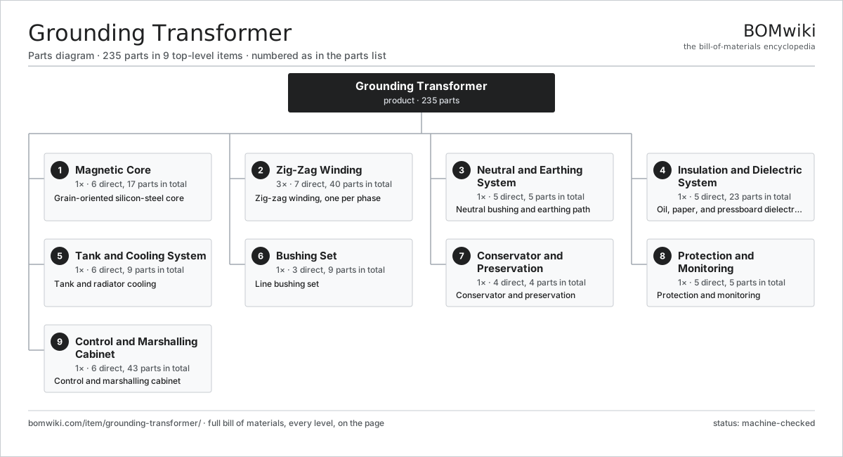
| # | Part | Qty | What it does |
|---|---|---|---|
| 1 | Magnetic Core 6 parts | 1× | Grain-oriented silicon-steel core |
| 2 | Zig-Zag Winding 7 parts | 3× | Zig-zag winding, one per phase |
| 3 | Neutral and Earthing System 5 parts | 1× | Neutral bushing and earthing path |
| 4 | Insulation and Dielectric System 5 parts | 1× | Oil, paper, and pressboard dielectric system |
| 5 | Tank and Cooling System 6 parts | 1× | Tank and radiator cooling |
| 6 | Bushing Set 3 parts | 1× | Line bushing set |
| 7 | Conservator and Preservation 4 parts | 1× | Conservator and preservation |
| 8 | Protection and Monitoring 5 parts | 1× | Protection and monitoring |
| 9 | Control and Marshalling Cabinet 6 parts | 1× | Control and marshalling cabinet |
3D model
No 3D model yet. Have a CAD file of this? Add a 3D model. STL renders right on this page; STEP, FreeCAD, and OpenSCAD sources are welcome too (openly licensed, like all 3D models on BOMwiki).
Build & assembly graph
expand / collapse · shared sub-assemblies converge · links to related products · est. labourTap an assembly to expand/collapse · tap a part to open it · use “Open page” for any node · drag to pan, scroll to zoom.
Bill of materials for Grounding Transformer
9 top-level lines · 56 rows shown · 235 parts total · indented to 3 levels| # | Item / sub-assembly | Part no. | Qty/assy | Ext. qty | Parts | Type |
|---|---|---|---|---|---|---|
| 1 | Magnetic Core 6 parts | grounding-transformer-core | 1× | 1 | 17 | assembly |
| 1.1 | GO Silicon-Steel Lamination | grounding-transformer-core-lamination | 1× | 1 | · | part |
| 1.2 | Core Limb | grounding-transformer-core-limb | 3× | 3 | · | part |
| 1.3 | Core Yoke | grounding-transformer-core-yoke | 2× | 2 | · | part |
| 1.4 | Core Clamping Frame | grounding-transformer-core-clamp | 4× | 4 | · | part |
| 1.5 | Core Tie Rod | grounding-transformer-core-tie-rod | 6× | 6 | · | part |
| 1.6 | Core Ground Strap | grounding-transformer-core-ground-strap | 1× | 1 | · | part |
| 2 | Zig-Zag Winding 7 parts | grounding-transformer-zigzag-winding | 3× | 3 | 40 | assembly |
| 2.1 | Winding Copper Conductor | grounding-transformer-winding-conductor | 1× | 3 | · | part |
| 2.2 | Zig-Zag Half-Winding | grounding-transformer-half-winding | 2× | 6 | · | part |
| 2.3 | Interconnection Lead | grounding-transformer-interconnection-lead | 1× | 3 | · | part |
| 2.4 | Winding Support Cylinder | grounding-transformer-winding-cylinder | 1× | 3 | · | part |
| 2.5 | Radial Spacer Block | grounding-transformer-spacer-block | 32× | 96 | · | part |
| 2.6 | Winding Clamp Ring | grounding-transformer-clamp-ring | 2× | 6 | · | part |
| 2.7 | Auxiliary Secondary Winding | grounding-transformer-aux-winding | 1× | 3 | · | part |
| 3 | Neutral and Earthing System 5 parts | grounding-transformer-neutral-system | 1× | 1 | 5 | assembly |
| 3.1 | Neutral Bushing | grounding-transformer-neutral-bushing | 1× | 1 | · | part |
| 3.2 | Neutral Current Transformer | grounding-transformer-neutral-ct | 1× | 1 | · | part |
| 3.3 | Neutral Earthing Resistor | grounding-transformer-earthing-resistor | 1× | 1 | · | part |
| 3.4 | Neutral Earthing Reactor | grounding-transformer-earthing-reactor | 1× | 1 | · | part |
| 3.5 | Earth-Grid Connection | grounding-transformer-earth-connection | 1× | 1 | · | part |
| 4 | Insulation and Dielectric System 5 parts | grounding-transformer-insulation | 1× | 1 | 23 | assembly |
| 4.1 | Mineral Insulating Oil | grounding-transformer-mineral-oil | 1× | 1 | · | part |
| 4.2 | Kraft Paper Insulation | grounding-transformer-paper-insulation | 1× | 1 | · | part |
| 4.3 | Pressboard Barrier | grounding-transformer-pressboard-barrier | 9× | 9 | · | part |
| 4.4 | Pressboard Angle Ring | grounding-transformer-angle-ring | 6× | 6 | · | part |
| 4.5 | Lead Support Frame | grounding-transformer-lead-support | 6× | 6 | · | part |
| 5 | Tank and Cooling System 6 parts | grounding-transformer-tank-cooling | 1× | 1 | 9 | assembly |
| 5.1 | Transformer Tank | grounding-transformer-tank | 1× | 1 | · | part |
| 5.2 | Tank Cover | grounding-transformer-tank-cover | 1× | 1 | · | part |
| 5.3 | Cooling Radiator | grounding-transformer-radiator | 4× | 4 | · | part |
| 5.4 | Oil Valve Set | grounding-transformer-valve-set | 1× | 1 | · | part |
| 5.5 | Transport Skid | grounding-transformer-skid | 1× | 1 | · | part |
| 5.6 | O-Ring Set | oring-set | 1× | 1 | · | part |
| 6 | Bushing Set 3 parts | grounding-transformer-bushings | 1× | 1 | 9 | assembly |
| 6.1 | Line Bushing | grounding-transformer-line-bushing | 3× | 3 | · | part |
| 6.2 | Bushing Current Transformer | grounding-transformer-bushing-ct | 3× | 3 | · | part |
| 6.3 | Bushing Turret | grounding-transformer-bushing-turret | 3× | 3 | · | part |
| 7 | Conservator and Preservation 4 parts | grounding-transformer-conservator | 1× | 1 | 4 | assembly |
| 7.1 | Conservator Tank | grounding-transformer-conservator-tank | 1× | 1 | · | part |
| 7.2 | Conservator Air Cell | grounding-transformer-air-cell | 1× | 1 | · | part |
| 7.3 | Silica-Gel Breather | grounding-transformer-silica-breather | 1× | 1 | · | part |
| 7.4 | Magnetic Oil-Level Gauge | grounding-transformer-oil-level-gauge | 1× | 1 | · | part |
| 8 | Protection and Monitoring 5 parts | grounding-transformer-protection | 1× | 1 | 5 | assembly |
| 8.1 | Buchholz Relay | grounding-transformer-buchholz | 1× | 1 | · | part |
| 8.2 | Pressure-Relief Device | grounding-transformer-pressure-relief | 1× | 1 | · | part |
| 8.3 | Top-Oil Temperature Indicator | grounding-transformer-oil-temp | 1× | 1 | · | part |
| 8.4 | Winding Temperature Indicator | grounding-transformer-winding-temp | 1× | 1 | · | part |
| 8.5 | Pressure Sensor | pressure-sensor | 1× | 1 | · | part |
| 9 | Control and Marshalling Cabinet 6 parts | grounding-transformer-marshalling | 1× | 1 | 43 | assembly |
| 9.1 | Marshalling Enclosure | grounding-transformer-cabinet-enclosure | 1× | 1 | · | part |
| 9.2 | Relay | relay | 8× | 8 | · | part |
| 9.3 | Field Terminal Block | grounding-transformer-terminal-block | 24× | 24 | · | part |
| 9.4 | Wire Bundle | wire-bundle | 1× | 1 | · | part |
| 9.5 | Connector | connector | 8× | 8 | · | part |
| 9.6 | Cabinet Space Heater | grounding-transformer-space-heater | 1× | 1 | · | part |
Related products
same domain, ranked by shared parts Autotransformer
7,784 parts · shares 3 with this page
Bottom Ash Handling System
1,782 parts · shares 3 with this page
Autotransformer
7,784 parts · shares 3 with this page
Bottom Ash Handling System
1,782 parts · shares 3 with this page
 Combined Heat and Power Unit
522 parts · shares 3 with this page
Containerized Diesel Genset
655 parts · shares 3 with this page
Combined Heat and Power Unit
522 parts · shares 3 with this page
Containerized Diesel Genset
655 parts · shares 3 with this page
 Distribution Ring Main Unit
443 parts · shares 3 with this page
Distribution Ring Main Unit
443 parts · shares 3 with this page
 Electric Arc Furnace Transformer
522 parts · shares 3 with this page
Electric Arc Furnace Transformer
522 parts · shares 3 with this page
Sourcing: possible vendors
Browse the supplier directory → Prices, MOQ, and lead times are algorithmic estimates, not quotes, and not claims about these companies. Company mappings are curated by keyword; est. price band $5k–$50M. How estimates work| Vendor | HQ | Specialty | MOQ | Lead time |
|---|---|---|---|---|
| gevernova.com ↗ | Cambridge, US | Power generation | made to order | 20–40 wks |
| siemens-energy.com ↗ | Munich, DE | Power & grid | made to order | 20–40 wks |
| hitachienergy.com ↗ | Zurich, CH | Grid & transformers | made to order | 20–40 wks |
|
🇨🇭ABB
abb.com ↗
|
Zurich, CH | Electrification & automation | made to order | 20–40 wks |
| se.com ↗ | Rueil-Malmaison, FR | Electrical & automation | made to order | 20–40 wks |
942-word article