Power Plant DCS Cabinet
ProductOverview
A power plant DCS cabinet is the equipment enclosure that houses the distributed control system running and monitoring a generating unit. It sits in or near the control room and ties the plant's field instruments and actuators to the operators and to the higher-level plant network. Inside one cabinet you find the controllers that execute the control logic, the input and output modules that read sensors and drive valves, the power and network gear that keep them alive and connected, and the marshalling hardware that lands hundreds of field cables.
A single cabinet typically supervises a section of the plant such as the boiler, the turbine, or the balance of plant. Larger units use several cabinets linked over a redundant control network. The design priority is availability: the unit must keep running and stay observable even when an individual module, supply, or network path fails. Every critical path in this cabinet is doubled.
How it works
Field transmitters send 4-20 mA, RTD, and thermocouple signals into the I/O subsystem, while contacts and limit switches report status as 24 VDC discrete inputs. The controller CPU reads the full process image once per scan, runs the IEC 61131-3 application, and writes new outputs back to the I/O modules. Analog outputs drive valve positioners and variable-speed drives through 4-20 mA loops; digital outputs energize solenoids, contactors, and indicators.
The scan cycle is fixed, usually between 10 and 100 ms depending on the loop, so control response is deterministic. Alarms, trends, and operator graphics are served to the operator interface drop, where the engineering workstation also holds the configuration and program for the cabinet.
Controller and I/O
The controller rack carries the CPUs, communication modules, and rack power on a passive backplane. Two CPU modules run as a 1oo2 hot-standby pair: one is the active controller and the other tracks it in lockstep. Each CPU keeps its program and retentive variables in a battery-backed retentive memory module so process state survives a power cycle.
The I/O is built from hot-swappable modules on their own I/O backplane. Analog inputs come in through 16-channel analog input modules using precision analog-to-digital converters and per-channel signal isolators. Control outputs go out through 8-channel analog output modules. Discrete signals use 32-channel digital input modules with input optocouplers and 16-channel digital output modules driving solid-state outputs. Temperatures are read by RTD and thermocouple modules with cold-junction compensation. Every module lands on a pluggable field termination assembly so a module can be swapped without touching field wiring.
Redundancy and power
Availability comes from removing single points of failure. The CPU pair fails over without a bump because the redundancy sync module mirrors the process image between the two controllers every scan over a dedicated fiber link. If the active CPU faults, the standby takes over within one to two scans and the unit keeps running.
Power is just as redundant. Two 24 VDC power supplies feed a redundancy diode module that ORs them onto a single 24 VDC bus, so either supply can fail with no interruption. From there a fused DC distribution rail feeds each subsystem on its own protected branch. A battery backup unit gives roughly 30 minutes of controlled ride-through so the unit can hold or trip safely during a mains outage.
Communication network
The cabinet connects to the plant over a redundant control network. Two managed ethernet switches form a ring with sub-50 ms recovery, carrying the controller traffic on separate VLANs from the operator and historian traffic. Fiber media converters extend segments to remote I/O cabinets over multimode fiber, which also gives galvanic isolation between buildings. The communication modules in the controller rack bridge to field buses such as Modbus TCP and Profibus DP, and IEC 61850 is used where the cabinet talks to electrical protection and switchgear. A historian collects trends over OPC UA for plant reporting.
Marshalling and field wiring
Plant cabling does not land directly on the I/O. It lands first in the marshalling panel, where roughly 200 terminal blocks cross-wire field cables to the I/O channels. High-power field commands pass through interposing relays so a small digital output can switch a contactor or motor starter. Fuse terminals protect each field loop, and loop isolators break ground loops on noisy analog signals. All of it mounts on DIN rail with slotted wire duct for routing. Surge protection and a copper ground bar bond every shield and metalwork to a single reference, and surge protective devices clamp transients on power, signal, and network entries.
Variants and use
The same cabinet platform scales from a small balance-of-plant panel to a full unit controller. Channel counts, the number of I/O modules, and the fieldbus mix change per application, but the redundancy scheme stays the same. Safety-related functions can run on the same controllers up to SIL 2 under IEC 61511, or move to a separate certified safety controller for higher integrity. Climate control inside the cabinet structure keeps electronics within rating: thermostat-switched fans pull filtered air for cooling, and an anti-condensation heater holds the interior above dew point during cold standby. Cabinets of this kind run on coal, gas, combined-cycle, hydro, and waste-to-energy plants, and the same design serves large industrial boilers and process utilities.
Power Plant DCS Cabinet parts and their functions
8 top-level parts · 1,441 parts in total · full bill of materials below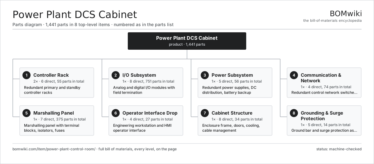
| # | Part | Qty | What it does |
|---|---|---|---|
| 1 | Controller Rack 6 parts | 2× | Redundant primary and standby controller racks |
| 2 | I/O Subsystem 8 parts | 1× | Analog and digital I/O modules with field termination |
| 3 | Power Subsystem 5 parts | 1× | Redundant power supplies, DC distribution, battery backup |
| 4 | Communication & Network 4 parts | 1× | Redundant control network switches and fiber links |
| 5 | Marshalling Panel 7 parts | 1× | Marshalling panel with terminal blocks, isolators, fuses |
| 6 | Operator Interface Drop 4 parts | 1× | Engineering workstation and HMI operator interface |
| 7 | Cabinet Structure 8 parts | 1× | Enclosure frame, doors, cooling, cable management |
| 8 | Grounding & Surge Protection 5 parts | 1× | Ground bar and surge protection assembly |
3D model
No 3D model yet. Have a CAD file of this? Add a 3D model. STL renders right on this page; STEP, FreeCAD, and OpenSCAD sources are welcome too (openly licensed, like all 3D models on BOMwiki).
Build & assembly graph
expand / collapse · shared sub-assemblies converge · links to related products · est. labourTap an assembly to expand/collapse · tap a part to open it · use “Open page” for any node · drag to pan, scroll to zoom.
Bill of materials for Power Plant DCS Cabinet
8 top-level lines · 164 rows shown · 1,441 parts total · indented to 3 levels| # | Item / sub-assembly | Part no. | Qty/assy | Ext. qty | Parts | Type |
|---|---|---|---|---|---|---|
| 1 | Controller Rack 6 parts | power-plant-control-room-controller-rack | 2× | 2 | 55 | assembly |
| 1.1 | Controller Backplane 3 parts | power-plant-control-room-backplane | 1× | 2 | 16 | assembly |
| 1.1.1 | Bare PCB | pcb-bare | 1× | 2 | · | part |
| 1.1.2 | Connector | connector | 14× | 28 | · | part |
| 1.1.3 | SMD Passive (R/C/L) | smd-passives | 1× | 2 | · | part |
| 1.2 | Controller CPU Module 5 parts | power-plant-control-room-cpu-module | 2× | 4 | 6 | assembly |
| 1.2.1 | Bare PCB | pcb-bare | 1× | 4 | · | part |
| 1.2.2 | Microcontroller | mcu | 1× | 4 | · | part |
| 1.2.3 | Retentive Memory Module | power-plant-control-room-memory-module | 1× | 4 | · | part |
| 1.2.4 | SMD Passive (R/C/L) | smd-passives | 1× | 4 | · | part |
| 1.2.5 | Connector | connector | 2× | 8 | · | part |
| 1.3 | Redundancy Sync Module 4 parts | power-plant-control-room-redundancy-link | 1× | 2 | 6 | assembly |
| 1.3.1 | Bare PCB | pcb-bare | 1× | 2 | · | part |
| 1.3.2 | SMD Passive (R/C/L) | smd-passives | 1× | 2 | · | part |
| 1.3.3 | Fiber Transceiver | power-plant-control-room-fiber-transceiver | 2× | 4 | · | part |
| 1.3.4 | Connector | connector | 2× | 4 | · | part |
| 1.4 | Communication Module 4 parts | power-plant-control-room-comm-module | 2× | 4 | 6 | assembly |
| 1.4.1 | Bare PCB | pcb-bare | 1× | 4 | · | part |
| 1.4.2 | Microcontroller | mcu | 1× | 4 | · | part |
| 1.4.3 | SMD Passive (R/C/L) | smd-passives | 1× | 4 | · | part |
| 1.4.4 | Connector | connector | 3× | 12 | · | part |
| 1.5 | Rack Power Converter 4 parts | power-plant-control-room-rack-psu | 2× | 4 | 4 | assembly |
| 1.5.1 | Power Supply | power-supply | 1× | 4 | · | part |
| 1.5.2 | Bare PCB | pcb-bare | 1× | 4 | · | part |
| 1.5.3 | SMD Passive (R/C/L) | smd-passives | 1× | 4 | · | part |
| 1.5.4 | Connector | connector | 1× | 4 | · | part |
| 1.6 | Fastener Set | fastener-set | 1× | 2 | · | part |
| 2 | I/O Subsystem 8 parts | power-plant-control-room-io-subsystem | 1× | 1 | 751 | assembly |
| 2.1 | I/O Backplane 3 parts | power-plant-control-room-io-backplane | 1× | 1 | 18 | assembly |
| 2.1.1 | Bare PCB | pcb-bare | 1× | 1 | · | part |
| 2.1.2 | Connector | connector | 16× | 16 | · | part |
| 2.1.3 | SMD Passive (R/C/L) | smd-passives | 1× | 1 | · | part |
| 2.2 | Analog Input Module 6 parts | power-plant-control-room-ai-module | 4× | 4 | 22 | assembly |
| 2.2.1 | Bare PCB | pcb-bare | 1× | 4 | · | part |
| 2.2.2 | Microcontroller | mcu | 1× | 4 | · | part |
| 2.2.3 | Analog-to-Digital Converter | power-plant-control-room-adc | 2× | 8 | · | part |
| 2.2.4 | Signal Isolator | power-plant-control-room-signal-isolator | 16× | 64 | · | part |
| 2.2.5 | SMD Passive (R/C/L) | smd-passives | 1× | 4 | · | part |
| 2.2.6 | Connector | connector | 1× | 4 | · | part |
| 2.3 | Analog Output Module 6 parts | power-plant-control-room-ao-module | 2× | 2 | 20 | assembly |
| 2.3.1 | Bare PCB | pcb-bare | 1× | 2 | · | part |
| 2.3.2 | Microcontroller | mcu | 1× | 2 | · | part |
| 2.3.3 | Digital-to-Analog Converter | power-plant-control-room-dac | 8× | 16 | · | part |
| 2.3.4 | Signal Isolator | power-plant-control-room-signal-isolator | 8× | 16 | · | part |
| 2.3.5 | SMD Passive (R/C/L) | smd-passives | 1× | 2 | · | part |
| 2.3.6 | Connector | connector | 1× | 2 | · | part |
| 2.4 | Digital Input Module 5 parts | power-plant-control-room-di-module | 4× | 4 | 36 | assembly |
| 2.4.1 | Bare PCB | pcb-bare | 1× | 4 | · | part |
| 2.4.2 | Microcontroller | mcu | 1× | 4 | · | part |
| 2.4.3 | Optocoupler | power-plant-control-room-optocoupler | 32× | 128 | · | part |
| 2.4.4 | SMD Passive (R/C/L) | smd-passives | 1× | 4 | · | part |
| 2.4.5 | Connector | connector | 1× | 4 | · | part |
| 2.5 | Digital Output Module 6 parts | power-plant-control-room-do-module | 4× | 4 | 36 | assembly |
| 2.5.1 | Bare PCB | pcb-bare | 1× | 4 | · | part |
| 2.5.2 | Microcontroller | mcu | 1× | 4 | · | part |
| 2.5.3 | Optocoupler | power-plant-control-room-optocoupler | 16× | 64 | · | part |
| 2.5.4 | Solid-State Output Driver | power-plant-control-room-output-fet | 16× | 64 | · | part |
| 2.5.5 | SMD Passive (R/C/L) | smd-passives | 1× | 4 | · | part |
| 2.5.6 | Connector | connector | 1× | 4 | · | part |
| 2.6 | RTD / Thermocouple Module 6 parts | power-plant-control-room-rtd-module | 2× | 2 | 6 | assembly |
| 2.6.1 | Bare PCB | pcb-bare | 1× | 2 | · | part |
| 2.6.2 | Microcontroller | mcu | 1× | 2 | · | part |
| 2.6.3 | Analog-to-Digital Converter | power-plant-control-room-adc | 1× | 2 | · | part |
| 2.6.4 | Cold-Junction Sensor | power-plant-control-room-cjc-sensor | 1× | 2 | · | part |
| 2.6.5 | SMD Passive (R/C/L) | smd-passives | 1× | 2 | · | part |
| 2.6.6 | Connector | connector | 1× | 2 | · | part |
| 2.7 | Field Termination Assembly 3 parts | power-plant-control-room-io-termination | 8× | 8 | 38 | assembly |
| 2.7.1 | Terminal Block | power-plant-control-room-terminal-block | 36× | 288 | · | part |
| 2.7.2 | Connector | connector | 1× | 8 | · | part |
| 2.7.3 | DIN Rail | power-plant-control-room-din-rail | 1× | 8 | · | part |
| 2.8 | Fastener Set | fastener-set | 1× | 1 | · | part |
| 3 | Power Subsystem 5 parts | power-plant-control-room-power-subsystem | 1× | 1 | 56 | assembly |
| 3.1 | 24 VDC Power Supply 4 parts | power-plant-control-room-psu | 2× | 2 | 5 | assembly |
| 3.1.1 | Power Supply | power-supply | 1× | 2 | · | part |
| 3.1.2 | Bare PCB | pcb-bare | 1× | 2 | · | part |
| 3.1.3 | SMD Passive (R/C/L) | smd-passives | 1× | 2 | · | part |
| 3.1.4 | Connector | connector | 2× | 4 | · | part |
| 3.2 | Redundancy Diode Module 4 parts | power-plant-control-room-redundancy-diode | 1× | 1 | 9 | assembly |
| 3.2.1 | Bare PCB | pcb-bare | 1× | 1 | · | part |
| 3.2.2 | ORing Diode | power-plant-control-room-or-diode | 4× | 4 | · | part |
| 3.2.3 | SMD Passive (R/C/L) | smd-passives | 1× | 1 | · | part |
| 3.2.4 | Connector | connector | 3× | 3 | · | part |
| 3.3 | DC Distribution Rail 4 parts | power-plant-control-room-dc-distribution | 1× | 1 | 28 | assembly |
| 3.3.1 | Fuse Terminal | power-plant-control-room-fuse-terminal | 24× | 24 | · | part |
| 3.3.2 | DIN Rail | power-plant-control-room-din-rail | 1× | 1 | · | part |
| 3.3.3 | Wire Bundle | wire-bundle | 1× | 1 | · | part |
| 3.3.4 | Connector | connector | 2× | 2 | · | part |
| 3.4 | Battery Backup Unit 3 parts | power-plant-control-room-battery-backup | 1× | 1 | 8 | assembly |
| 3.4.1 | VRLA Battery Bank | power-plant-control-room-battery-bank | 1× | 1 | · | part |
| 3.4.2 | Battery Charger Board 4 parts + deeper › | power-plant-control-room-charger-board | 1× | 1 | 5 | assembly |
| 3.4.3 | Connector | connector | 2× | 2 | · | part |
| 3.5 | Fastener Set | fastener-set | 1× | 1 | · | part |
| 4 | Communication & Network 4 parts | power-plant-control-room-network-subsystem | 1× | 1 | 74 | assembly |
| 4.1 | Managed Ethernet Switch 6 parts | power-plant-control-room-ethernet-switch | 2× | 2 | 14 | assembly |
| 4.1.1 | Bare PCB | pcb-bare | 1× | 2 | · | part |
| 4.1.2 | Microcontroller | mcu | 1× | 2 | · | part |
| 4.1.3 | Switch Fabric ASIC | power-plant-control-room-switch-asic | 1× | 2 | · | part |
| 4.1.4 | Fiber Transceiver | power-plant-control-room-fiber-transceiver | 2× | 4 | · | part |
| 4.1.5 | Connector | connector | 8× | 16 | · | part |
| 4.1.6 | SMD Passive (R/C/L) | smd-passives | 1× | 2 | · | part |
| 4.2 | Fiber Media Converter 4 parts | power-plant-control-room-media-converter | 4× | 4 | 5 | assembly |
| 4.2.1 | Bare PCB | pcb-bare | 1× | 4 | · | part |
| 4.2.2 | Fiber Transceiver | power-plant-control-room-fiber-transceiver | 1× | 4 | · | part |
| 4.2.3 | SMD Passive (R/C/L) | smd-passives | 1× | 4 | · | part |
| 4.2.4 | Connector | connector | 2× | 8 | · | part |
| 4.3 | Patch Panel 2 parts | power-plant-control-room-patch-panel | 1× | 1 | 25 | assembly |
| 4.3.1 | Sheet Metal Panel | sheet-panel | 1× | 1 | · | part |
| 4.3.2 | Connector | connector | 24× | 24 | · | part |
| 4.4 | Wire Bundle | wire-bundle | 1× | 1 | · | part |
| 5 | Marshalling Panel 7 parts | power-plant-control-room-marshalling | 1× | 1 | 375 | assembly |
| 5.1 | Terminal Block | power-plant-control-room-terminal-block | 200× | 200 | · | part |
| 5.2 | Interposing Relay 2 parts | power-plant-control-room-interposing-relay | 24× | 24 | 2 | assembly |
| 5.2.1 | Relay | relay | 1× | 24 | · | part |
| 5.2.2 | Relay Socket | power-plant-control-room-relay-socket | 1× | 24 | · | part |
| 5.3 | Fuse Terminal | power-plant-control-room-fuse-terminal | 48× | 48 | · | part |
| 5.4 | Loop Signal Isolator 4 parts | power-plant-control-room-loop-isolator | 16× | 16 | 4 | assembly |
| 5.4.1 | Bare PCB | pcb-bare | 1× | 16 | · | part |
| 5.4.2 | Signal Isolator | power-plant-control-room-signal-isolator | 1× | 16 | · | part |
| 5.4.3 | SMD Passive (R/C/L) | smd-passives | 1× | 16 | · | part |
| 5.4.4 | Connector | connector | 1× | 16 | · | part |
| 5.5 | DIN Rail | power-plant-control-room-din-rail | 6× | 6 | · | part |
| 5.6 | Slotted Wire Duct | power-plant-control-room-wire-duct | 8× | 8 | · | part |
| 5.7 | Wire Bundle | wire-bundle | 1× | 1 | · | part |
| 6 | Operator Interface Drop 4 parts | power-plant-control-room-operator-drop | 1× | 1 | 27 | assembly |
| 6.1 | Engineering Workstation PC 6 parts | power-plant-control-room-workstation-pc | 1× | 1 | 17 | assembly |
| 6.1.1 | Workstation Motherboard 4 parts + deeper › | power-plant-control-room-motherboard | 1× | 1 | 9 | assembly |
| 6.1.2 | Microcontroller | mcu | 1× | 1 | · | part |
| 6.1.3 | Power Supply | power-supply | 1× | 1 | · | part |
| 6.1.4 | Industrial SSD | power-plant-control-room-ssd | 1× | 1 | · | part |
| 6.1.5 | Sheet Metal Panel | sheet-panel | 1× | 1 | · | part |
| 6.1.6 | Connector | connector | 4× | 4 | · | part |
| 6.2 | HMI Monitor 5 parts | power-plant-control-room-hmi-monitor | 1× | 1 | 6 | assembly |
| 6.2.1 | LCD Panel | lcd-panel | 1× | 1 | · | part |
| 6.2.2 | Bare PCB | pcb-bare | 1× | 1 | · | part |
| 6.2.3 | Power Supply | power-supply | 1× | 1 | · | part |
| 6.2.4 | Sheet Metal Panel | sheet-panel | 1× | 1 | · | part |
| 6.2.5 | Connector | connector | 2× | 2 | · | part |
| 6.3 | Industrial Keyboard | power-plant-control-room-keyboard | 1× | 1 | · | part |
| 6.4 | Connector | connector | 3× | 3 | · | part |
| 7 | Cabinet Structure 8 parts | power-plant-control-room-cabinet-structure | 1× | 1 | 34 | assembly |
| 7.1 | Enclosure Frame | power-plant-control-room-frame | 1× | 1 | · | part |
| 7.2 | Cabinet Door 4 parts | power-plant-control-room-door | 2× | 2 | 4 | assembly |
| 7.2.1 | Sheet Metal Panel | sheet-panel | 1× | 2 | · | part |
| 7.2.2 | Door Lock | power-plant-control-room-door-lock | 1× | 2 | · | part |
| 7.2.3 | O-Ring Set | oring-set | 1× | 2 | · | part |
| 7.2.4 | Wire Bundle | wire-bundle | 1× | 2 | · | part |
| 7.3 | Sheet Metal Panel | sheet-panel | 4× | 4 | · | part |
| 7.4 | Cable Tray | power-plant-control-room-cable-tray | 4× | 4 | · | part |
| 7.5 | Cooling Fan Unit 3 parts | power-plant-control-room-cooling-fan | 4× | 4 | 3 | assembly |
| 7.5.1 | Axial Fan | power-plant-control-room-fan | 1× | 4 | · | part |
| 7.5.2 | Filter Mat | power-plant-control-room-filter-mat | 1× | 4 | · | part |
| 7.5.3 | Sheet Metal Panel | sheet-panel | 1× | 4 | · | part |
| 7.6 | Thermostat / Hygrostat | power-plant-control-room-thermostat | 1× | 1 | · | part |
| 7.7 | Anti-Condensation Heater 3 parts | power-plant-control-room-cabinet-heater | 1× | 1 | 3 | assembly |
| 7.7.1 | Heating Element | heating-element | 1× | 1 | · | part |
| 7.7.2 | Axial Fan | power-plant-control-room-fan | 1× | 1 | · | part |
| 7.7.3 | Connector | connector | 1× | 1 | · | part |
| 7.8 | Fastener Set | fastener-set | 1× | 1 | · | part |
| 8 | Grounding & Surge Protection 5 parts | power-plant-control-room-grounding-surge | 1× | 1 | 14 | assembly |
| 8.1 | Equipotential Ground Bar | power-plant-control-room-ground-bar | 1× | 1 | · | part |
| 8.2 | Power Surge Protector | power-plant-control-room-spd-power | 2× | 2 | · | part |
| 8.3 | Signal Surge Protector | power-plant-control-room-spd-signal | 8× | 8 | · | part |
| 8.4 | Network Surge Protector | power-plant-control-room-spd-network | 2× | 2 | · | part |
| 8.5 | Wire Bundle | wire-bundle | 1× | 1 | · | part |
Related products
same domain, ranked by shared parts Gas-Insulated Switchgear
281 parts · shares 6 with this page
Gas-Insulated Switchgear
281 parts · shares 6 with this page
 SCR NOx Reduction Unit
569 parts · shares 6 with this page
SCR NOx Reduction Unit
569 parts · shares 6 with this page
 Substation Capacitor Bank
3,464 parts · shares 6 with this page
Substation Capacitor Bank
3,464 parts · shares 6 with this page
 Electrostatic Precipitator
879 parts · shares 4 with this page
Electrostatic Precipitator
879 parts · shares 4 with this page
 Phase-Shifting Transformer
203 parts · shares 4 with this page
Phase-Shifting Transformer
203 parts · shares 4 with this page
 Coal Pulverizer Mill
313 parts · shares 4 with this page
Coal Pulverizer Mill
313 parts · shares 4 with this page
Sourcing: possible vendors
Browse the supplier directory → Prices, MOQ, and lead times are algorithmic estimates, not quotes, and not claims about these companies. Company mappings are curated by keyword; est. price band $5k–$50M. How estimates work| Vendor | HQ | Specialty | MOQ | Lead time |
|---|---|---|---|---|
| gevernova.com ↗ | Cambridge, US | Power generation | made to order | 20–40 wks |
| siemens-energy.com ↗ | Munich, DE | Power & grid | made to order | 20–40 wks |
| hitachienergy.com ↗ | Zurich, CH | Grid & transformers | made to order | 20–40 wks |
|
🇨🇭ABB
abb.com ↗
|
Zurich, CH | Electrification & automation | made to order | 20–40 wks |
| se.com ↗ | Rueil-Malmaison, FR | Electrical & automation | made to order | 20–40 wks |
1,108-word article