Distribution Ring Main Unit
ProductOverview
A ring main unit (RMU) is the switching node that connects a distribution transformer to a medium-voltage ring network. In a ring layout the cable enters one RMU, passes through to the next, and so on around a loop fed from two directions. Each RMU has two ring (line) ways that carry the through current of the ring and a transformer tee that taps off to the local substation. The unit shown is the common 2L + 1F arrangement: two Load-Break Switch ways and one Fuse-Switch Tee feeder, abbreviated CCF (two switch-disconnectors, one fuse combination).
The whole live assembly sits inside a sealed SF6 Gas Tank filled with SF6. Sealing the switching contacts in gas lets the unit be compact, weatherproof and maintenance-free for its service life, which is why RMUs dominate compact and pad-mounted secondary substations. A 12 kV 2L + 1F unit fits in roughly 1170 by 750 mm and weighs about 320 kg, small enough for a kiosk or basement substation.
How it works
Through current enters on one ring way, runs along the internal copper busbar, and leaves on the other ring way, keeping the ring energised. The transformer is fed from the busbar through the fuse-switch tee. To take the transformer out of service an operator opens the tee switch, then moves its Three-Position Switch to the earth position, which both isolates and grounds the transformer cable so work can proceed safely. Opening a ring switch lets a section of cable be isolated while the rest of the ring stays fed from the other direction.
Each switching way is driven by its own Spring Operating Mechanism. The operator charges a spring with the Manual Operating Handle; releasing it snaps the contacts open or closed at a fixed speed regardless of how slowly the handle was moved. That load-independent speed is what makes consistent arc interruption possible.
Switchgear and arc interruption
Each load-break switch has three phases, one Fixed Contact and one rotating Rotating Moving Contact per phase, sharing a single insulated Insulated Drive Shaft. When the switch opens under load, the current does not stop cleanly; an arc forms across the parting contacts. The Puffer Arc Chamber handles it with a puffer principle: as the moving contact travels, a PTFE Puffer Cylinder compresses the surrounding SF6 and blows it through a Blast Nozzle across the arc. SF6 is an excellent arc quencher because it captures free electrons and recombines quickly, so the arc extinguishes at the first natural current zero. A separate Arcing Contact of tungsten-copper takes the arc damage and parts last, leaving the silver-plated main contacts clean for low resistance when closed.
Insulation and SF6 tank
The tank is a laser-welded Stainless Tank Shell of 304L stainless steel, sealed for life so the gas is never handled in the field. It holds about 3 kg of SF6 Insulating Gas at only 0.04 MPa gauge, a low pressure that keeps the tank light and limits any leak. SF6 at this pressure withstands far more voltage than air over the same gap, which is what allows the contacts to sit so close together.
Current crosses the tank wall through cast Epoxy Bushing units, three per way, each a Cast Epoxy Body around a Conductor Stud sealed with an o-ring. Gas condition is watched by a temperature-compensated SF6 Density Monitor built on a Pressure Sensor; it reads density rather than raw pressure so it ignores normal temperature swings, raising an alarm and then a lockout if gas is lost. A Rupture Disc rupture disc protects against the pressure rise of an internal fault by venting away from the operator.
Fuse-switch tee
The transformer feeder pairs a load-break switch with three HRC Current-Limiting Fuse current-limiting fuses, one per phase, mounted in withdrawable Fuse Carrier holders. The switch makes and breaks normal load and magnetising current; the fuses clear short circuits. An HRC fuse limits a fault by melting its silver element in a fraction of a cycle, well before the current reaches its prospective peak, which protects the transformer and the downstream cable.
When any one fuse blows, its Striker Pin fires and pushes the shared Striker Trip Bar, tripping the switch on all three phases. That single-phasing protection stops a transformer running on two phases after one fuse operates. The tee also carries an Earthing Switch to ground the transformer cable for safe work.
Operating mechanism
The Spring Operating Mechanism is a spring-charged snap unit. A Coil Spring pair stores the energy, held by a Charging Ratchet until a release fires. For remote operation a Closing Coil and a Shunt Trip Coil let the protection relay or SCADA close and trip the switch electrically, while the Auxiliary Switch Block block reports position back to the control system. A Mechanism Cam Shaft sequences the motion so charging, closing and tripping cannot collide.
Variants and use
RMUs are configured by way count and type: CCF (2L + 1F) is the standard transformer node, CCC adds a third switch for a tee-off, and four-way and five-way extensible designs serve larger substations. The same platform is offered at 12 kV and 24 kV by scaling the bushing creepage and the gas gaps, with short-circuit ratings of 16, 20 or 21 kA for one second. A Control & Protection Box adds a self-powered protection relay, current transformers and a Fault Passage Indicator fault passage indicator, turning a manual unit into a remotely monitored ring node. Cables terminate on touch-safe Screened Elbow Connector separable connectors, so the unit is dead-front and safe to stand in front of while live. Typical applications are urban distribution rings, compact secondary substations, wind and solar collector networks, and industrial site feeders.
Distribution Ring Main Unit parts and their functions
8 top-level parts · 443 parts in total · full bill of materials below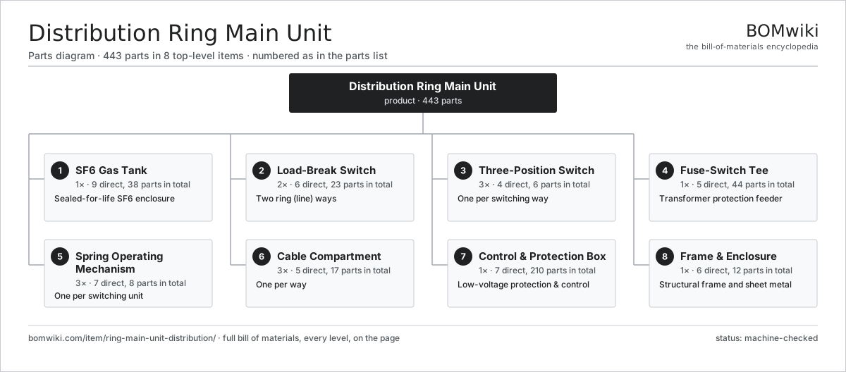
| # | Part | Qty | What it does |
|---|---|---|---|
| 1 | SF6 Gas Tank 9 parts | 1× | Sealed-for-life SF6 enclosure |
| 2 | Load-Break Switch 6 parts | 2× | Two ring (line) ways |
| 3 | Three-Position Switch 4 parts | 3× | One per switching way |
| 4 | Fuse-Switch Tee 5 parts | 1× | Transformer protection feeder |
| 5 | Spring Operating Mechanism 7 parts | 3× | One per switching unit |
| 6 | Cable Compartment 5 parts | 3× | One per way |
| 7 | Control & Protection Box 7 parts | 1× | Low-voltage protection & control |
| 8 | Frame & Enclosure 6 parts | 1× | Structural frame and sheet metal |
3D model
No 3D model yet. Have a CAD file of this? Add a 3D model. STL renders right on this page; STEP, FreeCAD, and OpenSCAD sources are welcome too (openly licensed, like all 3D models on BOMwiki).
Build & assembly graph
expand / collapse · shared sub-assemblies converge · links to related products · est. labourTap an assembly to expand/collapse · tap a part to open it · use “Open page” for any node · drag to pan, scroll to zoom.
Bill of materials for Distribution Ring Main Unit
8 top-level lines · 91 rows shown · 443 parts total · indented to 3 levels| # | Item / sub-assembly | Part no. | Qty/assy | Ext. qty | Parts | Type |
|---|---|---|---|---|---|---|
| 1 | SF6 Gas Tank 9 parts | ring-main-unit-distribution-gas-tank | 1× | 1 | 38 | assembly |
| 1.1 | Stainless Tank Shell | ring-main-unit-distribution-tank-shell | 1× | 1 | · | part |
| 1.2 | Tank Lid Plate | ring-main-unit-distribution-tank-lid | 1× | 1 | · | part |
| 1.3 | SF6 Insulating Gas | ring-main-unit-distribution-sf6-gas | 1× | 1 | · | part |
| 1.4 | SF6 Density Monitor 3 parts | ring-main-unit-distribution-density-monitor | 1× | 1 | 4 | assembly |
| 1.4.1 | Pressure Sensor | pressure-sensor | 1× | 1 | · | part |
| 1.4.2 | Density Gauge Dial | ring-main-unit-distribution-gauge-dial | 1× | 1 | · | part |
| 1.4.3 | Density Alarm Microswitch | ring-main-unit-distribution-alarm-microswitch | 2× | 2 | · | part |
| 1.5 | Rupture Disc | ring-main-unit-distribution-pressure-relief | 1× | 1 | · | part |
| 1.6 | Gas Fill Valve | ring-main-unit-distribution-fill-valve | 1× | 1 | · | part |
| 1.7 | Epoxy Bushing 3 parts | ring-main-unit-distribution-epoxy-bushing | 9× | 9 | 3 | assembly |
| 1.7.1 | Cast Epoxy Body | ring-main-unit-distribution-epoxy-body | 1× | 9 | · | part |
| 1.7.2 | Conductor Stud | ring-main-unit-distribution-conductor-stud | 1× | 9 | · | part |
| 1.7.3 | O-Ring Set | oring-set | 1× | 9 | · | part |
| 1.8 | O-Ring Set | oring-set | 1× | 1 | · | part |
| 1.9 | Fastener Set | fastener-set | 1× | 1 | · | part |
| 2 | Load-Break Switch 6 parts | ring-main-unit-distribution-load-break-switch | 2× | 2 | 23 | assembly |
| 2.1 | Fixed Contact | ring-main-unit-distribution-fixed-contact | 3× | 6 | · | part |
| 2.2 | Rotating Moving Contact | ring-main-unit-distribution-moving-contact | 3× | 6 | · | part |
| 2.3 | Puffer Arc Chamber 3 parts | ring-main-unit-distribution-arc-chamber | 3× | 6 | 4 | assembly |
| 2.3.1 | Puffer Cylinder | ring-main-unit-distribution-puffer-cylinder | 1× | 6 | · | part |
| 2.3.2 | Arcing Contact | ring-main-unit-distribution-arcing-contact | 2× | 12 | · | part |
| 2.3.3 | Blast Nozzle | ring-main-unit-distribution-nozzle | 1× | 6 | · | part |
| 2.4 | Insulated Drive Shaft | ring-main-unit-distribution-drive-shaft | 1× | 2 | · | part |
| 2.5 | Position Indicator | ring-main-unit-distribution-position-indicator | 1× | 2 | · | part |
| 2.6 | Contact Pressure Spring | ring-main-unit-distribution-contact-spring | 3× | 6 | · | part |
| 3 | Three-Position Switch 4 parts | ring-main-unit-distribution-three-position-switch | 3× | 3 | 6 | assembly |
| 3.1 | Selector Drum | ring-main-unit-distribution-selector-drum | 1× | 3 | · | part |
| 3.2 | Earthing Blade | ring-main-unit-distribution-earth-blade | 3× | 9 | · | part |
| 3.3 | Interlock Cam | ring-main-unit-distribution-interlock-cam | 1× | 3 | · | part |
| 3.4 | Detent Spring | ring-main-unit-distribution-detent-spring | 1× | 3 | · | part |
| 4 | Fuse-Switch Tee 5 parts | ring-main-unit-distribution-fuse-switch-tee | 1× | 1 | 44 | assembly |
| 4.1 | Load-Break Switch 6 parts | ring-main-unit-distribution-load-break-switch | 1× | 1 | 23 | assembly |
| 4.1.1 | Fixed Contact | ring-main-unit-distribution-fixed-contact | 3× | 3 | · | part |
| 4.1.2 | Rotating Moving Contact | ring-main-unit-distribution-moving-contact | 3× | 3 | · | part |
| 4.1.3 | Puffer Arc Chamber 3 parts + deeper › | ring-main-unit-distribution-arc-chamber | 3× | 3 | 4 | assembly |
| 4.1.4 | Insulated Drive Shaft | ring-main-unit-distribution-drive-shaft | 1× | 1 | · | part |
| 4.1.5 | Position Indicator | ring-main-unit-distribution-position-indicator | 1× | 1 | · | part |
| 4.1.6 | Contact Pressure Spring | ring-main-unit-distribution-contact-spring | 3× | 3 | · | part |
| 4.2 | HRC Current-Limiting Fuse 3 parts | ring-main-unit-distribution-hrc-fuse | 3× | 3 | 4 | assembly |
| 4.2.1 | Fuse Body | ring-main-unit-distribution-fuse-body | 1× | 3 | · | part |
| 4.2.2 | Striker Pin | ring-main-unit-distribution-striker-pin | 1× | 3 | · | part |
| 4.2.3 | Fuse End Cap | ring-main-unit-distribution-fuse-cap | 2× | 6 | · | part |
| 4.3 | Fuse Carrier | ring-main-unit-distribution-fuse-carrier | 3× | 3 | · | part |
| 4.4 | Striker Trip Bar | ring-main-unit-distribution-striker-trip-bar | 1× | 1 | · | part |
| 4.5 | Earthing Switch 3 parts | ring-main-unit-distribution-earthing-switch | 1× | 1 | 5 | assembly |
| 4.5.1 | Earthing Blade | ring-main-unit-distribution-earth-blade | 3× | 3 | · | part |
| 4.5.2 | Earth Bus Bar | ring-main-unit-distribution-earth-bar | 1× | 1 | · | part |
| 4.5.3 | Coil Spring | coil-spring | 1× | 1 | · | part |
| 5 | Spring Operating Mechanism 7 parts | ring-main-unit-distribution-operating-mechanism | 3× | 3 | 8 | assembly |
| 5.1 | Coil Spring | coil-spring | 2× | 6 | · | part |
| 5.2 | Shunt Trip Coil | ring-main-unit-distribution-trip-coil | 1× | 3 | · | part |
| 5.3 | Closing Coil | ring-main-unit-distribution-close-coil | 1× | 3 | · | part |
| 5.4 | Mechanism Cam Shaft | ring-main-unit-distribution-cam-shaft | 1× | 3 | · | part |
| 5.5 | Charging Ratchet | ring-main-unit-distribution-ratchet | 1× | 3 | · | part |
| 5.6 | Manual Operating Handle | ring-main-unit-distribution-manual-handle | 1× | 3 | · | part |
| 5.7 | Auxiliary Switch Block | ring-main-unit-distribution-aux-switch | 1× | 3 | · | part |
| 6 | Cable Compartment 5 parts | ring-main-unit-distribution-cable-compartment | 3× | 3 | 17 | assembly |
| 6.1 | Screened Elbow Connector 3 parts | ring-main-unit-distribution-elbow-connector | 3× | 9 | 3 | assembly |
| 6.1.1 | Elbow Connector Body | ring-main-unit-distribution-elbow-body | 1× | 9 | · | part |
| 6.1.2 | Compression Cable Lug | ring-main-unit-distribution-cable-lug | 1× | 9 | · | part |
| 6.1.3 | Capacitive Test Point | ring-main-unit-distribution-test-point | 1× | 9 | · | part |
| 6.2 | Cable Gland Box | ring-main-unit-distribution-cable-box | 1× | 3 | · | part |
| 6.3 | Surge Arrester | ring-main-unit-distribution-surge-arrester | 3× | 9 | · | part |
| 6.4 | Voltage Presence Indicator | ring-main-unit-distribution-voltage-indicator | 1× | 3 | · | part |
| 6.5 | Cable Clamp | ring-main-unit-distribution-cable-clamp | 3× | 9 | · | part |
| 7 | Control & Protection Box 7 parts | ring-main-unit-distribution-control-box | 1× | 1 | 210 | assembly |
| 7.1 | Feeder Protection Relay 4 parts | ring-main-unit-distribution-protection-relay | 1× | 1 | 93 | assembly |
| 7.1.1 | Bare PCB | pcb-bare | 1× | 1 | · | part |
| 7.1.2 | Microcontroller | mcu | 1× | 1 | · | part |
| 7.1.3 | SMD Passive (R/C/L) | smd-passives | 90× | 90 | · | part |
| 7.1.4 | LCD Panel | lcd-panel | 1× | 1 | · | part |
| 7.2 | Current Transformer | ring-main-unit-distribution-current-transformer | 3× | 3 | · | part |
| 7.3 | Relay | relay | 2× | 2 | · | part |
| 7.4 | Fault Passage Indicator 3 parts | ring-main-unit-distribution-fpi-unit | 1× | 1 | 42 | assembly |
| 7.4.1 | Bare PCB | pcb-bare | 1× | 1 | · | part |
| 7.4.2 | Microcontroller | mcu | 1× | 1 | · | part |
| 7.4.3 | SMD Passive (R/C/L) | smd-passives | 40× | 40 | · | part |
| 7.5 | Auxiliary Power Supply 3 parts | ring-main-unit-distribution-aux-supply | 1× | 1 | 63 | assembly |
| 7.5.1 | Bare PCB | pcb-bare | 1× | 1 | · | part |
| 7.5.2 | SMD Passive (R/C/L) | smd-passives | 60× | 60 | · | part |
| 7.5.3 | Connector | connector | 2× | 2 | · | part |
| 7.6 | Wire Bundle | wire-bundle | 1× | 1 | · | part |
| 7.7 | Connector | connector | 6× | 6 | · | part |
| 8 | Frame & Enclosure 6 parts | ring-main-unit-distribution-frame-enclosure | 1× | 1 | 12 | assembly |
| 8.1 | Base Frame | ring-main-unit-distribution-base-frame | 1× | 1 | · | part |
| 8.2 | Sheet Metal Panel | sheet-panel | 6× | 6 | · | part |
| 8.3 | Mimic Front Panel | ring-main-unit-distribution-front-panel | 1× | 1 | · | part |
| 8.4 | Compartment Latch | ring-main-unit-distribution-door-latch | 2× | 2 | · | part |
| 8.5 | Internal-Arc Relief Flap | ring-main-unit-distribution-pressure-relief-flap | 1× | 1 | · | part |
| 8.6 | Fastener Set | fastener-set | 1× | 1 | · | part |
Related products
same domain, ranked by shared parts Combined Heat and Power Unit
522 parts · shares 6 with this page
Combined Heat and Power Unit
522 parts · shares 6 with this page
 Large Synchronous Generator
42,357 parts · shares 6 with this page
Large Synchronous Generator
42,357 parts · shares 6 with this page
 Geothermal Wellhead
274 parts · shares 5 with this page
Geothermal Wellhead
274 parts · shares 5 with this page
 Large Power Transformer
1,844 parts · shares 5 with this page
Large Power Transformer
1,844 parts · shares 5 with this page
 Overhead Line Recloser
84 parts · shares 5 with this page
Overhead Line Recloser
84 parts · shares 5 with this page
Sourcing: possible vendors
Browse the supplier directory → Prices, MOQ, and lead times are algorithmic estimates, not quotes, and not claims about these companies. Company mappings are curated by keyword; est. price band $5k–$50M. How estimates work| Vendor | HQ | Specialty | MOQ | Lead time |
|---|---|---|---|---|
| gevernova.com ↗ | Cambridge, US | Power generation | made to order | 20–40 wks |
| siemens-energy.com ↗ | Munich, DE | Power & grid | made to order | 20–40 wks |
| hitachienergy.com ↗ | Zurich, CH | Grid & transformers | made to order | 20–40 wks |
|
🇨🇭ABB
abb.com ↗
|
Zurich, CH | Electrification & automation | made to order | 20–40 wks |
| se.com ↗ | Rueil-Malmaison, FR | Electrical & automation | made to order | 20–40 wks |
1,086-word article