Substation Capacitor Bank
ProductOverview
A substation capacitor bank is a switched assembly of power capacitors that injects reactive power into a transmission or distribution bus. Reactive power does no net work, but inductive loads such as motors, transformers, and long lines consume it, and supplying it locally raises the power factor, frees up generator and line capacity, and holds the bus voltage up. This bank is an outdoor open-rack shunt design rated 25.2 Mvar at 34.5 kV, grounded wye, fuseless. It sits on a concrete pad inside a fenced yard and is energized and de-energized as the system reactive demand rises and falls.
The bank is built from many small building blocks. The reactive output comes from dozens of power capacitor units wired into three phase stacks. Everything else on the rack exists to support those cans, to insulate them, to switch them onto the bus cleanly, and to detect when one of them fails. The major subsystems are the capacitor stacks, the steel rack structure, the series detuning reactors, the capacitor switcher, the unbalance protection set, the surge and insulation set, the grounding and neutral set, and the control cabinet.
How it works
Reactive output scales with the square of the applied voltage and the total capacitance. At 34.5 kV and 25.2 Mvar the bank draws about 422 A per phase. To reach that rating each phase carries 21 units of 400 kvar, grouped three in series by seven in parallel, so the per-unit voltage stays within the 400 kvar can rating while the parallel groups build up the current. The three phases connect to a common neutral bus in a grounded-wye arrangement.
When the substation controller sees the power factor drop or the bus voltage sag, it commands the capacitor switcher to close. Energizing a capacitor onto a stiff bus would otherwise draw a large inrush spike, so the controlled switching relay times each pole to close near its voltage zero, and small inrush reactors limit the remaining transient. After the bank is opened, the stored charge has to be drained before anyone can approach it; an internal discharge resistor in every unit and the external discharge VTs bring the residual voltage under 50 V within five minutes.
Capacitor units
The capacitor unit is the heart of the bank. Each is a welded stainless steel tank holding roughly 60 wound capacitor elements of polypropylene film. The elements are connected in series and parallel by internal straps to set the 400 kvar rating, then the whole pack is vacuum-impregnated with a non-PCB dielectric fluid that fills every void and suppresses partial discharge. Two porcelain bushings bring the terminals through the lid.
This is a fuseless bank, so there are no external expulsion fuses on each can. Instead the elements within a unit are arranged so that a single element failure shorts out cleanly and the string keeps operating with a slightly reduced reactance. That small change is exactly what the protection watches for. Units are clamped to the rack on galvanized mounting cradles and joined by string busbars and braided flexible connectors that absorb thermal expansion.
Rack and configuration
The rack structure is a hot-dip galvanized steel frame that holds the capacitor strings in tiers above the pad. In a grounded-wye fuseless bank the rack tiers float at different potentials, so the frame sits on support insulators and the high-voltage terminals carry corona grading rings to keep the field below the corona threshold. The rack is anchored to the concrete pad with foundation anchor bolts and bonded to the station ground grid. A perimeter fence with an interlocked gate enforces the live clearance.
Detuning and harmonics
A shunt capacitor and the source inductance form a resonant circuit. If that resonance lands on a harmonic the load produces, currents and voltages can amplify and overheat the bank. To move the resonance out of the way each phase carries a series detuning reactor, a dry-type air-core coil braced on fiberglass spiders and raised on pedestal insulators. At 6 percent reactance the bank series-resonates near 204 Hz, below the fifth harmonic at 300 Hz, so the combination looks inductive to every harmonic the plant generates and presents a low-impedance sink rather than a resonant trap.
Protection and switching
Because there are no per-can fuses, the bank relies on the unbalance protection set. A failed element shifts the balance of the wye, and the neutral CT sees the resulting neutral current while the voltage transformers track the phase voltages. The unbalance relay alarms on the first failure and trips before a cascade overstresses the survivors. A measurement control unit compensates for slow capacitance drift with temperature and age so normal ageing is not mistaken for a fault. The switcher itself uses three vacuum interrupters driven by a magnetic operating mechanism, and the surge arresters clamp the switching and lightning overvoltages.
Variants and use
The same building blocks scale across voltage classes. Distribution banks at 13.8 kV use fewer series groups and a smaller BIL; transmission banks at 115 kV stack more units in series and add taller station-post insulators. Externally fused designs replace the fuseless element logic with expulsion fuses on each can, trading simpler unit construction for visible fuse operation. Utilities deploy these banks at substations and on feeders for power-factor correction, voltage support during peak load, and release of upstream capacity. The control cabinet ties the bank into substation SCADA so dispatch can switch it on schedule, on measured reactive demand, or on voltage.
Substation Capacitor Bank parts and their functions
8 top-level parts · 3,464 parts in total · full bill of materials below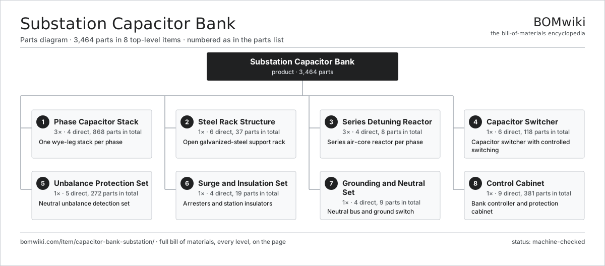
| # | Part | Qty | What it does |
|---|---|---|---|
| 1 | Phase Capacitor Stack 4 parts | 3× | One wye-leg stack per phase |
| 2 | Steel Rack Structure 6 parts | 1× | Open galvanized-steel support rack |
| 3 | Series Detuning Reactor 4 parts | 3× | Series air-core reactor per phase |
| 4 | Capacitor Switcher 6 parts | 1× | Capacitor switcher with controlled switching |
| 5 | Unbalance Protection Set 5 parts | 1× | Neutral unbalance detection set |
| 6 | Surge and Insulation Set 4 parts | 1× | Arresters and station insulators |
| 7 | Grounding and Neutral Set 4 parts | 1× | Neutral bus and ground switch |
| 8 | Control Cabinet 9 parts | 1× | Bank controller and protection cabinet |
3D model
No 3D model yet. Have a CAD file of this? Add a 3D model. STL renders right on this page; STEP, FreeCAD, and OpenSCAD sources are welcome too (openly licensed, like all 3D models on BOMwiki).
Build & assembly graph
expand / collapse · shared sub-assemblies converge · links to related products · est. labourTap an assembly to expand/collapse · tap a part to open it · use “Open page” for any node · drag to pan, scroll to zoom.
Bill of materials for Substation Capacitor Bank
8 top-level lines · 89 rows shown · 3,464 parts total · indented to 3 levels| # | Item / sub-assembly | Part no. | Qty/assy | Ext. qty | Parts | Type |
|---|---|---|---|---|---|---|
| 1 | Phase Capacitor Stack 4 parts | capacitor-bank-substation-capacitor-stack | 3× | 3 | 868 | assembly |
| 1.1 | Power Capacitor Unit 6 parts | capacitor-bank-substation-capacitor-unit | 12× | 36 | 69 | assembly |
| 1.1.1 | Capacitor Element | capacitor-bank-substation-capacitor-element | 60× | 2,160 | · | part |
| 1.1.2 | Capacitor Tank | capacitor-bank-substation-capacitor-tank | 1× | 36 | · | part |
| 1.1.3 | Porcelain Terminal Bushing | capacitor-bank-substation-porcelain-bushing | 2× | 72 | · | part |
| 1.1.4 | Internal Discharge Resistor | capacitor-bank-substation-discharge-resistor | 1× | 36 | · | part |
| 1.1.5 | Dielectric Impregnant Fluid | capacitor-bank-substation-impregnant-fluid | 1× | 36 | · | part |
| 1.1.6 | Internal Connection Strap | capacitor-bank-substation-internal-busbar | 4× | 144 | · | part |
| 1.2 | String Interconnection Busbar | capacitor-bank-substation-string-busbar | 4× | 12 | · | part |
| 1.3 | Unit Mounting Cradle | capacitor-bank-substation-unit-mounting-bracket | 12× | 36 | · | part |
| 1.4 | Flexible Terminal Connector | capacitor-bank-substation-flexible-connector | 24× | 72 | · | part |
| 2 | Steel Rack Structure 6 parts | capacitor-bank-substation-rack-structure | 1× | 1 | 37 | assembly |
| 2.1 | Galvanized Steel Rack Frame | capacitor-bank-substation-rack-frame | 1× | 1 | · | part |
| 2.2 | Rack Support Insulator | capacitor-bank-substation-rack-insulator | 12× | 12 | · | part |
| 2.3 | Corona Grading Ring | capacitor-bank-substation-grading-ring | 6× | 6 | · | part |
| 2.4 | Perimeter Safety Fence | capacitor-bank-substation-safety-fence | 1× | 1 | · | part |
| 2.5 | Foundation Anchor Bolt | capacitor-bank-substation-foundation-anchor | 16× | 16 | · | part |
| 2.6 | Fastener Set | fastener-set | 1× | 1 | · | part |
| 3 | Series Detuning Reactor 4 parts | capacitor-bank-substation-detuning-reactor | 3× | 3 | 8 | assembly |
| 3.1 | Air-Core Reactor Coil | capacitor-bank-substation-reactor-coil | 1× | 3 | · | part |
| 3.2 | Reactor Spider Support | capacitor-bank-substation-reactor-spider | 2× | 6 | · | part |
| 3.3 | Reactor Pedestal Insulator | capacitor-bank-substation-reactor-insulator | 3× | 9 | · | part |
| 3.4 | Reactor Terminal Pad | capacitor-bank-substation-reactor-terminal | 2× | 6 | · | part |
| 4 | Capacitor Switcher 6 parts | capacitor-bank-substation-switching-device | 1× | 1 | 118 | assembly |
| 4.1 | Vacuum Interrupter | capacitor-bank-substation-vacuum-interrupter | 3× | 3 | · | part |
| 4.2 | Switcher Operating Mechanism 4 parts | capacitor-bank-substation-switcher-operating-mechanism | 1× | 1 | 12 | assembly |
| 4.2.1 | Magnetic Actuator Coil | capacitor-bank-substation-actuator-coil | 3× | 3 | · | part |
| 4.2.2 | Coil Spring | coil-spring | 6× | 6 | · | part |
| 4.2.3 | Relay | relay | 2× | 2 | · | part |
| 4.2.4 | Fastener Set | fastener-set | 1× | 1 | · | part |
| 4.3 | Switcher Pole Insulator | capacitor-bank-substation-pole-insulator | 3× | 3 | · | part |
| 4.4 | Controlled Switching Relay 4 parts | capacitor-bank-substation-controlled-switching-relay | 1× | 1 | 95 | assembly |
| 4.4.1 | Bare PCB | pcb-bare | 1× | 1 | · | part |
| 4.4.2 | Microcontroller | mcu | 1× | 1 | · | part |
| 4.4.3 | SMD Passive (R/C/L) | smd-passives | 90× | 90 | · | part |
| 4.4.4 | Relay | relay | 3× | 3 | · | part |
| 4.5 | Inrush-Limiting Reactor | capacitor-bank-substation-inrush-reactor | 3× | 3 | · | part |
| 4.6 | Auxiliary Contact Switch | capacitor-bank-substation-auxiliary-switch | 2× | 2 | · | part |
| 5 | Unbalance Protection Set 5 parts | capacitor-bank-substation-unbalance-protection | 1× | 1 | 272 | assembly |
| 5.1 | Neutral Unbalance CT | capacitor-bank-substation-neutral-ct | 1× | 1 | · | part |
| 5.2 | Unbalance Protection Relay 5 parts | capacitor-bank-substation-unbalance-relay | 1× | 1 | 147 | assembly |
| 5.2.1 | Bare PCB | pcb-bare | 1× | 1 | · | part |
| 5.2.2 | Microcontroller | mcu | 1× | 1 | · | part |
| 5.2.3 | SMD Passive (R/C/L) | smd-passives | 140× | 140 | · | part |
| 5.2.4 | Relay | relay | 4× | 4 | · | part |
| 5.2.5 | LCD Panel | lcd-panel | 1× | 1 | · | part |
| 5.3 | Sensing Voltage Transformer | capacitor-bank-substation-voltage-transformer | 3× | 3 | · | part |
| 5.4 | Measurement Control Unit 4 parts | capacitor-bank-substation-protection-cmu | 1× | 1 | 118 | assembly |
| 5.4.1 | Bare PCB | pcb-bare | 1× | 1 | · | part |
| 5.4.2 | Microcontroller | mcu | 1× | 1 | · | part |
| 5.4.3 | SMD Passive (R/C/L) | smd-passives | 110× | 110 | · | part |
| 5.4.4 | Connector | connector | 6× | 6 | · | part |
| 5.5 | Bank Line CT | capacitor-bank-substation-line-ct | 3× | 3 | · | part |
| 6 | Surge and Insulation Set 4 parts | capacitor-bank-substation-surge-insulation | 1× | 1 | 19 | assembly |
| 6.1 | Metal-Oxide Surge Arrester | capacitor-bank-substation-surge-arrester | 3× | 3 | · | part |
| 6.2 | Station-Post Insulator | capacitor-bank-substation-station-post-insulator | 6× | 6 | · | part |
| 6.3 | Apparatus Support Insulator | capacitor-bank-substation-support-insulator | 9× | 9 | · | part |
| 6.4 | Tubular Bus Conductor | capacitor-bank-substation-bus-conductor | 1× | 1 | · | part |
| 7 | Grounding and Neutral Set 4 parts | capacitor-bank-substation-grounding-neutral | 1× | 1 | 9 | assembly |
| 7.1 | Neutral Bus | capacitor-bank-substation-neutral-bus | 1× | 1 | · | part |
| 7.2 | Maintenance Ground Switch | capacitor-bank-substation-ground-switch | 1× | 1 | · | part |
| 7.3 | Discharge Voltage Transformer | capacitor-bank-substation-discharge-vt | 3× | 3 | · | part |
| 7.4 | Ground Grid Down-Lead | capacitor-bank-substation-ground-grid-lead | 4× | 4 | · | part |
| 8 | Control Cabinet 9 parts | capacitor-bank-substation-control-cabinet | 1× | 1 | 381 | assembly |
| 8.1 | Capacitor Bank Controller 5 parts | capacitor-bank-substation-bank-controller | 1× | 1 | 194 | assembly |
| 8.1.1 | Bare PCB | pcb-bare | 1× | 1 | · | part |
| 8.1.2 | Microcontroller | mcu | 1× | 1 | · | part |
| 8.1.3 | SMD Passive (R/C/L) | smd-passives | 180× | 180 | · | part |
| 8.1.4 | Relay | relay | 4× | 4 | · | part |
| 8.1.5 | Connector | connector | 8× | 8 | · | part |
| 8.2 | Control Cabinet Enclosure 3 parts | capacitor-bank-substation-cabinet-enclosure | 1× | 1 | 8 | assembly |
| 8.2.1 | Sheet Metal Panel | sheet-panel | 6× | 6 | · | part |
| 8.2.2 | O-Ring Set | oring-set | 1× | 1 | · | part |
| 8.2.3 | Fastener Set | fastener-set | 1× | 1 | · | part |
| 8.3 | Local HMI Display 4 parts | capacitor-bank-substation-hmi-display | 1× | 1 | 63 | assembly |
| 8.3.1 | LCD Panel | lcd-panel | 1× | 1 | · | part |
| 8.3.2 | Bare PCB | pcb-bare | 1× | 1 | · | part |
| 8.3.3 | Microcontroller | mcu | 1× | 1 | · | part |
| 8.3.4 | SMD Passive (R/C/L) | smd-passives | 60× | 60 | · | part |
| 8.4 | SCADA Comms Module 4 parts | capacitor-bank-substation-comms-module | 1× | 1 | 76 | assembly |
| 8.4.1 | Bare PCB | pcb-bare | 1× | 1 | · | part |
| 8.4.2 | Microcontroller | mcu | 1× | 1 | · | part |
| 8.4.3 | SMD Passive (R/C/L) | smd-passives | 70× | 70 | · | part |
| 8.4.4 | Connector | connector | 4× | 4 | · | part |
| 8.5 | Relay | relay | 6× | 6 | · | part |
| 8.6 | Power Supply | power-supply | 1× | 1 | · | part |
| 8.7 | Heating Element | heating-element | 2× | 2 | · | part |
| 8.8 | Wire Bundle | wire-bundle | 1× | 1 | · | part |
| 8.9 | Connector | connector | 30× | 30 | · | part |
Related products
same domain, ranked by shared parts Electrostatic Precipitator
879 parts · shares 5 with this page
Electrostatic Precipitator
879 parts · shares 5 with this page
 Coal Pulverizer Mill
313 parts · shares 5 with this page
Coal Pulverizer Mill
313 parts · shares 5 with this page
 Gas-Insulated Switchgear
281 parts · shares 6 with this page
Power Plant DCS Cabinet
1,441 parts · shares 6 with this page
Gas-Insulated Switchgear
281 parts · shares 6 with this page
Power Plant DCS Cabinet
1,441 parts · shares 6 with this page
 SCR NOx Reduction Unit
569 parts · shares 6 with this page
SCR NOx Reduction Unit
569 parts · shares 6 with this page
 Phase-Shifting Transformer
203 parts · shares 4 with this page
Phase-Shifting Transformer
203 parts · shares 4 with this page
Sourcing: possible vendors
Browse the supplier directory → Prices, MOQ, and lead times are algorithmic estimates, not quotes, and not claims about these companies. Company mappings are curated by keyword; est. price band $5k–$50M. How estimates work| Vendor | HQ | Specialty | MOQ | Lead time |
|---|---|---|---|---|
| gevernova.com ↗ | Cambridge, US | Power generation | made to order | 20–40 wks |
| siemens-energy.com ↗ | Munich, DE | Power & grid | made to order | 20–40 wks |
| hitachienergy.com ↗ | Zurich, CH | Grid & transformers | made to order | 20–40 wks |
|
🇨🇭ABB
abb.com ↗
|
Zurich, CH | Electrification & automation | made to order | 20–40 wks |
| se.com ↗ | Rueil-Malmaison, FR | Electrical & automation | made to order | 20–40 wks |
1,163-word article