Large Power Transformer
ProductOverview
A large power transformer is the workhorse of a transmission substation. It links two voltage levels, for example a 400 kV transmission line and a 132 kV sub-transmission system, and lets bulk power move between them with very little loss. A unit of this size is a custom-engineered machine, not a catalogue product: it is designed for one substation, built over many months, and expected to run for forty years or more. The whole assembly is built around the Active Part, the magnetic core and the copper windings, which sits immersed in oil inside a welded steel Tank & Conservator.
Almost everything else on the transformer exists to protect that active part or to carry heat away from it. The oil is both the dielectric that withstands the voltage and the coolant that moves the losses to the radiators. Bushings bring the conductors safely through the tank wall. The tap changer trims the ratio so the output voltage stays inside limits as the grid load swings through the day.
How it works
The transformer works by mutual induction. Alternating current in the HV Winding sets up an alternating flux in the laminated core. That flux links the LV Winding wound on the same limb and induces a voltage in it proportional to the turns ratio. With roughly three times as many turns on the 400 kV side as on the 132 kV side, the voltage steps down by about three to one and, ideally, the current steps up by the same factor. A third Tertiary Winding is connected in delta to give a path for third-harmonic currents and to supply station auxiliaries.
Because real windings have resistance and leakage flux, some energy is lost as heat. At 300 MVA even an efficiency of 99.7 % means close to a megawatt of heat to remove. That heat is what sizes the cooling plant.
Core and windings
The core is stacked from thin laminations of CRGO Core Laminations, grain-oriented silicon steel about 0.23 mm thick, cut and overlapped with step-lap mitred joints so the flux crosses the joint smoothly and the no-load loss and hum stay low. The limbs are bound with Core Banding and clamped between two Core Clamping Frame frames drawn together by insulated Core Tie Rod bolts. The core is earthed at a single point through Core Earthing Strip so no stray circulating current can flow.
The windings are wound from Paper-Covered Copper Conductor, continuously transposed copper covered in Kraft paper. Discs are separated by Pressboard Disc Spacer blocks that keep vertical oil ducts open for cooling, and the major insulation between windings and to earth is built up from Major Insulation Set pressboard barriers. The windings are clamped axially so they can survive the violent magnetic forces of a through-fault, when short-circuit current can reach twenty times the rated value for a fraction of a second.
Tank, oil and cooling
The active part is lowered into the Main Tank, a welded boiler-plate vessel stiffened against vacuum and pressure, then the tank is filled with degassed Insulating Mineral Oil under vacuum. As the oil heats and cools it expands and contracts, so a Conservator Tank tank above the main tank takes up the volume change. A Air-Cell Bladder separates the oil from the atmosphere, and the air that moves in and out passes through a Dehydrating Breather full of silica gel that keeps moisture out. A Buchholz Relay in the connecting pipe catches gas from an incipient internal fault and trips the transformer before a small fault becomes a fire.
Heat is rejected through the Cooling System. At light load, oil rises through the windings and falls through the Panel Radiator banks by natural convection alone, the ONAN stage. As load climbs, a Radiator Cooling Fan group switches on to force air across the radiators, and at full load a Oil Circulation Pump forces oil through them as well. The cooler controller stages these against measured temperature, so the same transformer carries far more load in OFAF mode than it could unaided.
On-load tap changer
Grid voltage is not constant, so the transformer must adjust its ratio while energised. The On-Load Tap Changer does this by switching connections on the Regulating Tap Winding. A Tap Selector pre-selects the next tap with no current breaking, then a fast Diverter Switch transfers the load current to it through Transition Resistor elements that limit the circulating current during the overlap. A Motor Drive Unit unit, controlled by a voltage-regulating relay, steps the changer one position at a time. The arcing happens in its own sealed oil compartment so the contamination never reaches the main tank oil.
Bushings and monitoring
Each line and neutral conductor leaves the tank through a Bushing Set. The HV terminals use HV RIP Bushing condenser bushings with graded foil layers and porcelain sheds for creepage, while Bushing Current Transformer current transformers around each bushing feed the protection. Operators watch the unit through the Monitoring & Control package: winding and oil temperature indicators, an oil level gauge, an online Dissolved-Gas Monitor that trends dissolved fault gases, and a Surge Arrester on each line to clamp lightning surges. All of it is wired back to a marshalling cabinet that also runs the cooler controls.
Materials and standards
The active materials are grain-oriented silicon steel for the core, electrolytic copper for the windings, and cellulose pressboard and Kraft paper for the solid insulation, all immersed in mineral oil. Tank and radiators are steel; bushing housings are high-alumina porcelain or composite. Such transformers are designed, tested and rated to IEC 60076 or the IEEE C57 series, which fix the temperature-rise limits, the impulse and applied-voltage test levels, and the short-circuit withstand the design must prove before it leaves the factory.
Large Power Transformer parts and their functions
7 top-level parts · 1,844 parts in total · full bill of materials below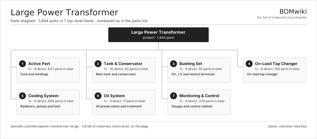
| # | Part | Qty | What it does |
|---|---|---|---|
| 1 | Active Part 8 parts | 1× | Core and windings |
| 2 | Tank & Conservator 10 parts | 1× | Main tank and conservator |
| 3 | Bushing Set 5 parts | 1× | HV, LV and neutral terminals |
| 4 | On-Load Tap Changer 6 parts | 1× | On-load tap changer |
| 5 | Cooling System 6 parts | 1× | Radiators, pumps and fans |
| 6 | Oil System 5 parts | 1× | Oil preservation and treatment |
| 7 | Monitoring & Control 6 parts | 1× | Gauges and control cabinet |
3D model
No 3D model yet. Have a CAD file of this? Add a 3D model. STL renders right on this page; STEP, FreeCAD, and OpenSCAD sources are welcome too (openly licensed, like all 3D models on BOMwiki).
Build & assembly graph
expand / collapse · shared sub-assemblies converge · links to related products · est. labourTap an assembly to expand/collapse · tap a part to open it · use “Open page” for any node · drag to pan, scroll to zoom.
Bill of materials for Large Power Transformer
7 top-level lines · 144 rows shown · 1,844 parts total · indented to 3 levels| # | Item / sub-assembly | Part no. | Qty/assy | Ext. qty | Parts | Type |
|---|---|---|---|---|---|---|
| 1 | Active Part 8 parts | power-transformer-large-active-part | 1× | 1 | 637 | assembly |
| 1.1 | Magnetic Core 4 parts | power-transformer-large-core | 1× | 1 | 16 | assembly |
| 1.1.1 | CRGO Core Laminations | power-transformer-large-core-lamination | 1× | 1 | · | part |
| 1.1.2 | Core Banding | power-transformer-large-core-band | 12× | 12 | · | part |
| 1.1.3 | Core Clamping Channel | power-transformer-large-core-channel | 2× | 2 | · | part |
| 1.1.4 | Core Earthing Strip | power-transformer-large-core-ground-strip | 1× | 1 | · | part |
| 1.2 | HV Winding 4 parts | power-transformer-large-hv-winding | 3× | 3 | 84 | assembly |
| 1.2.1 | Paper-Covered Copper Conductor | power-transformer-large-cu-conductor | 1× | 3 | · | part |
| 1.2.2 | Pressboard Disc Spacer | power-transformer-large-disc-spacer | 80× | 240 | · | part |
| 1.2.3 | Winding Pressing Ring | power-transformer-large-press-ring | 2× | 6 | · | part |
| 1.2.4 | Pressboard Cylinder | power-transformer-large-winding-cylinder | 1× | 3 | · | part |
| 1.3 | LV Winding 4 parts | power-transformer-large-lv-winding | 3× | 3 | 64 | assembly |
| 1.3.1 | Paper-Covered Copper Conductor | power-transformer-large-cu-conductor | 1× | 3 | · | part |
| 1.3.2 | Pressboard Disc Spacer | power-transformer-large-disc-spacer | 60× | 180 | · | part |
| 1.3.3 | Winding Pressing Ring | power-transformer-large-press-ring | 2× | 6 | · | part |
| 1.3.4 | Pressboard Cylinder | power-transformer-large-winding-cylinder | 1× | 3 | · | part |
| 1.4 | Tertiary Winding 3 parts | power-transformer-large-tertiary-winding | 3× | 3 | 32 | assembly |
| 1.4.1 | Paper-Covered Copper Conductor | power-transformer-large-cu-conductor | 1× | 3 | · | part |
| 1.4.2 | Pressboard Disc Spacer | power-transformer-large-disc-spacer | 30× | 90 | · | part |
| 1.4.3 | Pressboard Cylinder | power-transformer-large-winding-cylinder | 1× | 3 | · | part |
| 1.5 | Major Insulation Set 4 parts | power-transformer-large-winding-insulation | 1× | 1 | 43 | assembly |
| 1.5.1 | Pressboard Angle Ring | power-transformer-large-angle-ring | 12× | 12 | · | part |
| 1.5.2 | End Insulation Block | power-transformer-large-end-block | 24× | 24 | · | part |
| 1.5.3 | Electrostatic Shield Ring | power-transformer-large-static-ring | 6× | 6 | · | part |
| 1.5.4 | Insulating Kraft Paper | power-transformer-large-kraft-paper | 1× | 1 | · | part |
| 1.6 | Core Clamping Frame | power-transformer-large-core-clamp | 2× | 2 | · | part |
| 1.7 | Core Tie Rod | power-transformer-large-tie-rod | 8× | 8 | · | part |
| 1.8 | Lead Exit Assembly 3 parts | power-transformer-large-lead-exit | 1× | 1 | 28 | assembly |
| 1.8.1 | Lead Support Cleat | power-transformer-large-lead-cleat | 18× | 18 | · | part |
| 1.8.2 | Flexible Copper Lead | power-transformer-large-flexible-lead | 9× | 9 | · | part |
| 1.8.3 | Lead Insulation | power-transformer-large-lead-insulation | 1× | 1 | · | part |
| 2 | Tank & Conservator 10 parts | power-transformer-large-tank-assembly | 1× | 1 | 62 | assembly |
| 2.1 | Main Tank 3 parts | power-transformer-large-main-tank | 1× | 1 | 38 | assembly |
| 2.1.1 | Sheet Metal Panel | sheet-panel | 14× | 14 | · | part |
| 2.1.2 | Tank Stiffener | power-transformer-large-tank-stiffener | 20× | 20 | · | part |
| 2.1.3 | Transport Roller | power-transformer-large-tank-wheel | 4× | 4 | · | part |
| 2.2 | Tank Cover | power-transformer-large-tank-cover | 1× | 1 | · | part |
| 2.3 | Conservator Tank 3 parts | power-transformer-large-conservator | 1× | 1 | 4 | assembly |
| 2.3.1 | Conservator Shell | power-transformer-large-conservator-shell | 1× | 1 | · | part |
| 2.3.2 | Magnetic Oil Level Gauge | power-transformer-large-magnetic-oil-gauge | 1× | 1 | · | part |
| 2.3.3 | Conservator Support Bracket | power-transformer-large-conservator-bracket | 2× | 2 | · | part |
| 2.4 | Air-Cell Bladder | power-transformer-large-conservator-bladder | 1× | 1 | · | part |
| 2.5 | Buchholz Relay 3 parts | power-transformer-large-buchholz-relay | 1× | 1 | 5 | assembly |
| 2.5.1 | Buchholz Float | power-transformer-large-buchholz-float | 2× | 2 | · | part |
| 2.5.2 | Relay | relay | 2× | 2 | · | part |
| 2.5.3 | Gas Sampling Cock | power-transformer-large-gas-test-cock | 1× | 1 | · | part |
| 2.6 | Pressure Relief Device | power-transformer-large-pressure-relief | 2× | 2 | · | part |
| 2.7 | Tank Gasket Set | power-transformer-large-tank-gasket | 1× | 1 | · | part |
| 2.8 | Fastener Set | fastener-set | 4× | 4 | · | part |
| 2.9 | Lifting & Jacking Lug | power-transformer-large-jacking-lug | 4× | 4 | · | part |
| 2.10 | Oil Drain Valve | power-transformer-large-drain-valve | 2× | 2 | · | part |
| 3 | Bushing Set 5 parts | power-transformer-large-bushing-set | 1× | 1 | 50 | assembly |
| 3.1 | HV RIP Bushing 5 parts | power-transformer-large-hv-bushing | 3× | 3 | 6 | assembly |
| 3.1.1 | RIP Condenser Core | power-transformer-large-bushing-core | 1× | 3 | · | part |
| 3.1.2 | Porcelain Insulator Shed | power-transformer-large-porcelain-shed | 1× | 3 | · | part |
| 3.1.3 | Bushing Mounting Flange | power-transformer-large-bushing-flange | 1× | 3 | · | part |
| 3.1.4 | Capacitance Test Tap | power-transformer-large-test-tap | 1× | 3 | · | part |
| 3.1.5 | O-Ring Set | oring-set | 2× | 6 | · | part |
| 3.2 | LV Bushing 4 parts | power-transformer-large-lv-bushing | 3× | 3 | 5 | assembly |
| 3.2.1 | RIP Condenser Core | power-transformer-large-bushing-core | 1× | 3 | · | part |
| 3.2.2 | Porcelain Insulator Shed | power-transformer-large-porcelain-shed | 1× | 3 | · | part |
| 3.2.3 | Bushing Mounting Flange | power-transformer-large-bushing-flange | 1× | 3 | · | part |
| 3.2.4 | O-Ring Set | oring-set | 2× | 6 | · | part |
| 3.3 | Neutral Bushing 3 parts | power-transformer-large-neutral-bushing | 1× | 1 | 3 | assembly |
| 3.3.1 | Porcelain Insulator Shed | power-transformer-large-porcelain-shed | 1× | 1 | · | part |
| 3.3.2 | Bushing Mounting Flange | power-transformer-large-bushing-flange | 1× | 1 | · | part |
| 3.3.3 | O-Ring Set | oring-set | 1× | 1 | · | part |
| 3.4 | Bushing Current Transformer | power-transformer-large-bushing-ct | 7× | 7 | · | part |
| 3.5 | Bushing Turret | power-transformer-large-bushing-turret | 7× | 7 | · | part |
| 4 | On-Load Tap Changer 6 parts | power-transformer-large-tap-changer | 1× | 1 | 100 | assembly |
| 4.1 | Diverter Switch 3 parts | power-transformer-large-diverter-switch | 1× | 1 | 24 | assembly |
| 4.1.1 | Diverter Main Contact | power-transformer-large-diverter-contact | 12× | 12 | · | part |
| 4.1.2 | Coil Spring | coil-spring | 6× | 6 | · | part |
| 4.1.3 | Arcing Contact Tip | power-transformer-large-arcing-contact | 6× | 6 | · | part |
| 4.2 | Tap Selector 3 parts | power-transformer-large-tap-selector | 1× | 1 | 36 | assembly |
| 4.2.1 | Selector Contact | power-transformer-large-selector-contact | 34× | 34 | · | part |
| 4.2.2 | Helical Gear Pair | gear-pair | 1× | 1 | · | part |
| 4.2.3 | Insulating Drive Shaft | power-transformer-large-insulating-shaft | 1× | 1 | · | part |
| 4.3 | Regulating Tap Winding | power-transformer-large-tap-winding | 1× | 1 | · | part |
| 4.4 | Motor Drive Unit 6 parts | power-transformer-large-motor-drive | 1× | 1 | 34 | assembly |
| 4.4.1 | Servo Motor 4 parts + deeper › | servo-motor | 1× | 1 | 24 | assembly |
| 4.4.2 | Gearbox Housing | gearbox-housing | 1× | 1 | · | part |
| 4.4.3 | Tap Position Indicator | power-transformer-large-position-indicator | 1× | 1 | · | part |
| 4.4.4 | Operations Counter | power-transformer-large-step-counter | 1× | 1 | · | part |
| 4.4.5 | Microcontroller | mcu | 1× | 1 | · | part |
| 4.4.6 | Relay | relay | 6× | 6 | · | part |
| 4.5 | OLTC Oil Compartment | power-transformer-large-oltc-oil-compartment | 1× | 1 | · | part |
| 4.6 | Transition Resistor | power-transformer-large-transition-resistor | 4× | 4 | · | part |
| 5 | Cooling System 6 parts | power-transformer-large-cooling-system | 1× | 1 | 606 | assembly |
| 5.1 | Panel Radiator 3 parts | power-transformer-large-radiator | 8× | 8 | 27 | assembly |
| 5.1.1 | Radiator Panel | power-transformer-large-radiator-panel | 24× | 192 | · | part |
| 5.1.2 | Radiator Isolating Valve | power-transformer-large-radiator-valve | 2× | 16 | · | part |
| 5.1.3 | Air Vent Plug | power-transformer-large-air-vent-plug | 1× | 8 | · | part |
| 5.2 | Oil Circulation Pump 5 parts | power-transformer-large-oil-pump | 2× | 2 | 29 | assembly |
| 5.2.1 | Pump Impeller | power-transformer-large-pump-impeller | 1× | 2 | · | part |
| 5.2.2 | Servo Motor 4 parts + deeper › | servo-motor | 1× | 2 | 24 | assembly |
| 5.2.3 | Ball Bearing | ball-bearing | 2× | 4 | · | part |
| 5.2.4 | Oil Seal | oil-seal | 1× | 2 | · | part |
| 5.2.5 | Pump Flow Monitor | power-transformer-large-flow-monitor | 1× | 2 | · | part |
| 5.3 | Radiator Cooling Fan 3 parts | power-transformer-large-cooling-fan | 12× | 12 | 26 | assembly |
| 5.3.1 | Servo Motor 4 parts + deeper › | servo-motor | 1× | 12 | 24 | assembly |
| 5.3.2 | Axial Fan Blade | power-transformer-large-fan-blade | 1× | 12 | · | part |
| 5.3.3 | Fan Guard | power-transformer-large-fan-guard | 1× | 12 | · | part |
| 5.4 | Oil Flow Indicator | power-transformer-large-oil-flow-indicator | 2× | 2 | · | part |
| 5.5 | Cooler Oil Header | power-transformer-large-cooler-header | 2× | 2 | · | part |
| 5.6 | Radiator Isolating Valve | power-transformer-large-radiator-valve | 16× | 16 | · | part |
| 6 | Oil System 5 parts | power-transformer-large-oil-system | 1× | 1 | 11 | assembly |
| 6.1 | Insulating Mineral Oil | power-transformer-large-mineral-oil | 1× | 1 | · | part |
| 6.2 | Dehydrating Breather 3 parts | power-transformer-large-dehydrating-breather | 1× | 1 | 3 | assembly |
| 6.2.1 | Silica Gel Desiccant | power-transformer-large-silica-gel | 1× | 1 | · | part |
| 6.2.2 | Breather Body | power-transformer-large-breather-body | 1× | 1 | · | part |
| 6.2.3 | Breather Oil Cup | power-transformer-large-oil-seal-cup | 1× | 1 | · | part |
| 6.3 | Oil Pipework | power-transformer-large-oil-piping | 1× | 1 | · | part |
| 6.4 | Oil Sampling Valve | power-transformer-large-oil-sampling-valve | 2× | 2 | · | part |
| 6.5 | Oil Shutoff Valve | power-transformer-large-shutoff-valve | 4× | 4 | · | part |
| 7 | Monitoring & Control 6 parts | power-transformer-large-monitoring | 1× | 1 | 378 | assembly |
| 7.1 | Winding Temperature Indicator 3 parts | power-transformer-large-winding-temp-gauge | 3× | 3 | 3 | assembly |
| 7.1.1 | Temperature Sensing Bulb | power-transformer-large-temp-sensor-bulb | 1× | 3 | · | part |
| 7.1.2 | Thermal Image Heater | power-transformer-large-heater-coil | 1× | 3 | · | part |
| 7.1.3 | Indicator Dial | power-transformer-large-gauge-dial | 1× | 3 | · | part |
| 7.2 | Oil Temperature Indicator 2 parts | power-transformer-large-oil-temp-gauge | 1× | 1 | 2 | assembly |
| 7.2.1 | Temperature Sensing Bulb | power-transformer-large-temp-sensor-bulb | 1× | 1 | · | part |
| 7.2.2 | Indicator Dial | power-transformer-large-gauge-dial | 1× | 1 | · | part |
| 7.3 | Dissolved-Gas Monitor 4 parts | power-transformer-large-gas-monitor | 1× | 1 | 83 | assembly |
| 7.3.1 | Bare PCB | pcb-bare | 1× | 1 | · | part |
| 7.3.2 | Microcontroller | mcu | 1× | 1 | · | part |
| 7.3.3 | Gas Measuring Cell | power-transformer-large-gas-cell | 1× | 1 | · | part |
| 7.3.4 | SMD Passive (R/C/L) | smd-passives | 80× | 80 | · | part |
| 7.4 | Tank Pressure Transmitter 3 parts | power-transformer-large-pressure-sensor-tank | 2× | 2 | 32 | assembly |
| 7.4.1 | Pressure Sensor | pressure-sensor | 1× | 2 | · | part |
| 7.4.2 | Bare PCB | pcb-bare | 1× | 2 | · | part |
| 7.4.3 | SMD Passive (R/C/L) | smd-passives | 30× | 60 | · | part |
| 7.5 | Marshalling Cabinet 7 parts | power-transformer-large-marshalling-box | 1× | 1 | 211 | assembly |
| 7.5.1 | Sheet Metal Panel | sheet-panel | 6× | 6 | · | part |
| 7.5.2 | Terminal Block | power-transformer-large-terminal-block | 60× | 60 | · | part |
| 7.5.3 | Cooler Control Unit 4 parts + deeper › | power-transformer-large-cooler-controller | 1× | 1 | 110 | assembly |
| 7.5.4 | Relay | relay | 20× | 20 | · | part |
| 7.5.5 | Miniature Circuit Breaker | power-transformer-large-mcb | 12× | 12 | · | part |
| 7.5.6 | Wire Bundle | wire-bundle | 1× | 1 | · | part |
| 7.5.7 | Anti-Condensation Heater | power-transformer-large-space-heater | 2× | 2 | · | part |
| 7.6 | Surge Arrester 3 parts | power-transformer-large-surge-arrester | 3× | 3 | 3 | assembly |
| 7.6.1 | Metal-Oxide Varistor Block | power-transformer-large-mov-block | 1× | 3 | · | part |
| 7.6.2 | Porcelain Insulator Shed | power-transformer-large-porcelain-shed | 1× | 3 | · | part |
| 7.6.3 | Grading Ring | power-transformer-large-grading-ring | 1× | 3 | · | part |
Related products
same domain, ranked by shared parts Combined Heat and Power Unit
522 parts · shares 20 with this page
Combined Heat and Power Unit
522 parts · shares 20 with this page
 Coal Pulverizer Mill
313 parts · shares 18 with this page
Coal Pulverizer Mill
313 parts · shares 18 with this page
 Automatic Voltage Regulator
83 parts · shares 17 with this page
Automatic Voltage Regulator
83 parts · shares 17 with this page
 Industrial Gas Turbine Package
2,053 parts · shares 17 with this page
Industrial Gas Turbine Package
2,053 parts · shares 17 with this page
 Air-Insulated Substation Bay
1,329 parts · shares 17 with this page
Air-Insulated Substation Bay
1,329 parts · shares 17 with this page
Sourcing: possible vendors
Browse the supplier directory → Prices, MOQ, and lead times are algorithmic estimates, not quotes, and not claims about these companies. Company mappings are curated by keyword; est. price band $5k–$50M. How estimates work| Vendor | HQ | Specialty | MOQ | Lead time |
|---|---|---|---|---|
| gevernova.com ↗ | Cambridge, US | Power generation | made to order | 20–40 wks |
| siemens-energy.com ↗ | Munich, DE | Power & grid | made to order | 20–40 wks |
| hitachienergy.com ↗ | Zurich, CH | Grid & transformers | made to order | 20–40 wks |
|
🇨🇭ABB
abb.com ↗
|
Zurich, CH | Electrification & automation | made to order | 20–40 wks |
| se.com ↗ | Rueil-Malmaison, FR | Electrical & automation | made to order | 20–40 wks |
1,063-word article