Geothermal Wellhead
ProductOverview
A geothermal wellhead is the surface assembly that caps a geothermal well and controls the steam and brine rising out of it. It anchors the casing strings, suspends the production tubing, seals the annular spaces between strings, and routes hot two-phase fluid into the gathering pipeline at a measured rate. Geothermal service is harsher than most oil and gas duty: the fluid carries wet steam at 180-350 C, dissolved CO2 and hydrogen sulphide, silica and carbonate scale, and chlorides that drive pitting and stress corrosion. The stack is built to API 6A like any wellhead, but with material classes and a thermal-growth allowance chosen for those conditions.
The assembly bolts up as a vertical stack. At the bottom the Casing Head Housing lands on the surface casing and carries the Slip-Type Casing Hanger that suspends the next string. Above it the Tubing Hanger sits in the tubing head spool and seals the production tubing. The Master Gate Valve gates sit on the main bore, the Wing Valve Assembly takes flow off to the side, and the Production Throttle Valve sets the rate. Spools join with Ring Joint Gasket (RTJ) ring seals and Fastener Set studs throughout.
How it works
Fluid leaves the reservoir up the production tubing and enters the tree through the tubing hanger. Two master gate valves in series guard the vertical bore. Each is a through-conduit slab gate: the Slab Gate either presents a full open bore or a solid metal face, with no intermediate throttling position, so the valve is run fully open or fully shut to protect the Floating Valve Seat faces from wire-drawing erosion. The lower master valve is the primary isolation; the upper master is the working valve used for routine shut-in.
Flow then turns out through the Flow Tee / Cross into the wing. The wing gate valve isolates the flow line, and a Swing Check Valve blocks reverse flow from the gathering system back into the well. Rate is set at the Production Throttle Valve, an angle choke whose tungsten-carbide Choke Trim (Bean & Cage) takes the pressure drop and the erosive load. A second wing carries the kill and bleed line for well control.
Subsystems
The Expansion Spool is specific to geothermal wells. When a well is brought on, the casing heats by several hundred degrees and grows axially; a slip joint between the Expansion Mandrel and its Expansion Housing, sealed by Dynamic Slip-Joint Seal rings, lets the casing stroke without buckling or overloading the stack.
During drilling and workover a BOP Stack replaces the tree. An Annular Preventer seals around any pipe size with a reinforced elastomer Annular Packing Element, and Ram Preventer preventers close pipe, blind, or shear Ram Block elements across the bore. A nitrogen-charged Hydraulic Accumulator Unit supplies the hydraulic energy to close the preventers if rig power is lost.
The Instrumentation Package package reads wellhead and flow-line pressure with a Pressure Sensor at each point, fluid temperature with an RTD Temperature Probe in a thermowell, and flow across an Orifice Plate. Local Bourdon Pressure Gauge readouts back up the Multivariable Transmitter signal sent to the plant control room. The whole stack stands in a Cellar & Support Structure structure: a concrete cellar around the conductor and a steel frame with an access platform.
Materials
Bodies and spools are forged AISI 4130 low-alloy steel at 75,000 psi minimum yield. Where the fluid is sour, parts follow API 6A material class EE and NACE MR0175 hardness limits to resist sulphide stress cracking. Wetted sealing surfaces use 410 stainless overlaid with tungsten carbide, since bare carbon steel would erode and scale within a season. High-temperature static seals use metal-to-metal Metal-to-Metal Seal Ring rings of Inconel 718 rather than elastomers, because nitrile and HNBR degrade above roughly 200 C. Stem sealing uses die-formed flexible graphite Stem Packing Set, which holds at temperature where polymer packings fail.
Variants
Low-enthalpy hot-water wells run at 1,000 psi class with a single master valve and a simpler tree. High-enthalpy dry-steam and flash fields use the 2,000 psi class, dual master valves, and a heavier expansion spool. Wells that produce highly saline brine specify duplex or super-duplex stainless trim and inhibitor injection ports. Reinjection wellheads, which push spent brine back into the field, reverse the flow path and add scale-monitoring access but share the same body castings.
Operation and maintenance
A well is brought on slowly: the master valves are cracked open, the casing and stack are allowed to warm and stroke on the expansion spool, then the throttle is opened to the design rate. Body and seat sealant is injected through Sealant Injection Fitting ports to maintain the gate seal as the carbide faces wear. Choke trim is a wear item and is replaced on a schedule set by the silica and chloride load. Periodic seal tests through the Seal Test Port verify that the casing pack-offs still hold annular pressure.
Failure modes
The dominant failure modes are erosion of the Choke Trim (Bean & Cage) and master valve seats from entrained silica, scale buildup that jams the gate, chloride pitting and stress corrosion cracking of stainless trim, and thermal fatigue at the flange ring grooves from repeated heat cycles. Loss of the dynamic Dynamic Slip-Joint Seal under thermal cycling is a known issue and is why these seals are spring-energized PTFE and graphite rather than plain elastomer. Routine sealant injection, scheduled trim replacement, and seal testing keep the stack within its API 6A pressure rating across the field life.
Geothermal Wellhead parts and their functions
9 top-level parts · 274 parts in total · full bill of materials below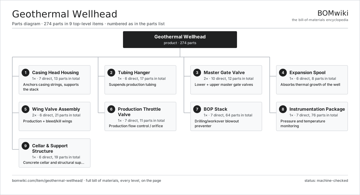
| # | Part | Qty | What it does |
|---|---|---|---|
| 1 | Casing Head Housing 7 parts | 1× | Anchors casing strings, supports the stack |
| 2 | Tubing Hanger 6 parts | 1× | Suspends production tubing |
| 3 | Master Gate Valve 10 parts | 2× | Lower + upper master gate valves |
| 4 | Expansion Spool 6 parts | 1× | Absorbs thermal growth of the well |
| 5 | Wing Valve Assembly 6 parts | 2× | Production + bleed/kill wings |
| 6 | Production Throttle Valve 7 parts | 1× | Production flow control / orifice |
| 7 | BOP Stack 7 parts | 1× | Drilling/workover blowout preventer |
| 8 | Instrumentation Package 7 parts | 1× | Pressure and temperature monitoring |
| 9 | Cellar & Support Structure 6 parts | 1× | Concrete cellar and structural support |
3D model
No 3D model yet. Have a CAD file of this? Add a 3D model. STL renders right on this page; STEP, FreeCAD, and OpenSCAD sources are welcome too (openly licensed, like all 3D models on BOMwiki).
Build & assembly graph
expand / collapse · shared sub-assemblies converge · links to related products · est. labourTap an assembly to expand/collapse · tap a part to open it · use “Open page” for any node · drag to pan, scroll to zoom.
Bill of materials for Geothermal Wellhead
9 top-level lines · 121 rows shown · 274 parts total · indented to 3 levels| # | Item / sub-assembly | Part no. | Qty/assy | Ext. qty | Parts | Type |
|---|---|---|---|---|---|---|
| 1 | Casing Head Housing 7 parts | geothermal-wellhead-casing-head | 1× | 1 | 13 | assembly |
| 1.1 | Casing Head Body | geothermal-wellhead-casing-head-body | 1× | 1 | · | part |
| 1.2 | Slip-Type Casing Hanger | geothermal-wellhead-casing-hanger | 1× | 1 | · | part |
| 1.3 | Casing Pack-Off Bushing 3 parts | geothermal-wellhead-casing-pack-off | 1× | 1 | 3 | assembly |
| 1.3.1 | Pack-Off Body | geothermal-wellhead-pack-off-body | 1× | 1 | · | part |
| 1.3.2 | O-Ring Set | oring-set | 1× | 1 | · | part |
| 1.3.3 | Seal Energizing Ring | geothermal-wellhead-energizing-ring | 1× | 1 | · | part |
| 1.4 | Ring Joint Gasket (RTJ) | geothermal-wellhead-rtj-gasket | 2× | 2 | · | part |
| 1.5 | Studded Flange | geothermal-wellhead-studded-flange | 2× | 2 | · | part |
| 1.6 | Fastener Set | fastener-set | 2× | 2 | · | part |
| 1.7 | Seal Test Port | geothermal-wellhead-test-port | 2× | 2 | · | part |
| 2 | Tubing Hanger 6 parts | geothermal-wellhead-tubing-hanger | 1× | 1 | 17 | assembly |
| 2.1 | Tubing Head Spool | geothermal-wellhead-tubing-head-spool | 1× | 1 | · | part |
| 2.2 | Tubing Hanger Mandrel | geothermal-wellhead-tubing-hanger-mandrel | 1× | 1 | · | part |
| 2.3 | Hanger Seal Assembly 2 parts | geothermal-wellhead-hanger-seal | 2× | 2 | 2 | assembly |
| 2.3.1 | Metal-to-Metal Seal Ring | geothermal-wellhead-mtm-seal | 1× | 2 | · | part |
| 2.3.2 | O-Ring Set | oring-set | 1× | 2 | · | part |
| 2.4 | Hanger Lockdown Screw | geothermal-wellhead-lockdown-screw | 8× | 8 | · | part |
| 2.5 | Ring Joint Gasket (RTJ) | geothermal-wellhead-rtj-gasket | 2× | 2 | · | part |
| 2.6 | Fastener Set | fastener-set | 1× | 1 | · | part |
| 3 | Master Gate Valve 10 parts | geothermal-wellhead-master-valve | 2× | 2 | 12 | assembly |
| 3.1 | Gate Valve Body | geothermal-wellhead-valve-body | 1× | 2 | · | part |
| 3.2 | Slab Gate | geothermal-wellhead-gate-slab | 1× | 2 | · | part |
| 3.3 | Floating Valve Seat | geothermal-wellhead-valve-seat | 2× | 4 | · | part |
| 3.4 | Valve Stem | geothermal-wellhead-valve-stem | 1× | 2 | · | part |
| 3.5 | Valve Bonnet | geothermal-wellhead-bonnet | 1× | 2 | · | part |
| 3.6 | Stem Packing Set | geothermal-wellhead-stem-packing | 1× | 2 | · | part |
| 3.7 | Handwheel | geothermal-wellhead-handwheel | 1× | 2 | · | part |
| 3.8 | Sealant Injection Fitting | geothermal-wellhead-grease-fitting | 2× | 4 | · | part |
| 3.9 | O-Ring Set | oring-set | 1× | 2 | · | part |
| 3.10 | Fastener Set | fastener-set | 1× | 2 | · | part |
| 4 | Expansion Spool 6 parts | geothermal-wellhead-expansion-spool | 1× | 1 | 8 | assembly |
| 4.1 | Expansion Mandrel | geothermal-wellhead-expansion-mandrel | 1× | 1 | · | part |
| 4.2 | Expansion Housing | geothermal-wellhead-expansion-housing | 1× | 1 | · | part |
| 4.3 | Dynamic Slip-Joint Seal | geothermal-wellhead-expansion-seal | 2× | 2 | · | part |
| 4.4 | Ring Joint Gasket (RTJ) | geothermal-wellhead-rtj-gasket | 2× | 2 | · | part |
| 4.5 | Coil Spring | coil-spring | 1× | 1 | · | part |
| 4.6 | Fastener Set | fastener-set | 1× | 1 | · | part |
| 5 | Wing Valve Assembly 6 parts | geothermal-wellhead-wing-valve-assy | 2× | 2 | 21 | assembly |
| 5.1 | Flow Tee / Cross | geothermal-wellhead-flow-tee | 1× | 2 | · | part |
| 5.2 | Master Gate Valve 10 parts | geothermal-wellhead-master-valve | 1× | 2 | 12 | assembly |
| 5.2.1 | Gate Valve Body | geothermal-wellhead-valve-body | 1× | 2 | · | part |
| 5.2.2 | Slab Gate | geothermal-wellhead-gate-slab | 1× | 2 | · | part |
| 5.2.3 | Floating Valve Seat | geothermal-wellhead-valve-seat | 2× | 4 | · | part |
| 5.2.4 | Valve Stem | geothermal-wellhead-valve-stem | 1× | 2 | · | part |
| 5.2.5 | Valve Bonnet | geothermal-wellhead-bonnet | 1× | 2 | · | part |
| 5.2.6 | Stem Packing Set | geothermal-wellhead-stem-packing | 1× | 2 | · | part |
| 5.2.7 | Handwheel | geothermal-wellhead-handwheel | 1× | 2 | · | part |
| 5.2.8 | Sealant Injection Fitting | geothermal-wellhead-grease-fitting | 2× | 4 | · | part |
| 5.2.9 | O-Ring Set | oring-set | 1× | 2 | · | part |
| 5.2.10 | Fastener Set | fastener-set | 1× | 2 | · | part |
| 5.3 | Swing Check Valve 4 parts | geothermal-wellhead-check-valve | 1× | 2 | 4 | assembly |
| 5.3.1 | Check Valve Body | geothermal-wellhead-check-body | 1× | 2 | · | part |
| 5.3.2 | Check Valve Disc | geothermal-wellhead-check-disc | 1× | 2 | · | part |
| 5.3.3 | Hinge Pin | geothermal-wellhead-check-pin | 1× | 2 | · | part |
| 5.3.4 | O-Ring Set | oring-set | 1× | 2 | · | part |
| 5.4 | Flow Line Flange | geothermal-wellhead-flow-line-flange | 1× | 2 | · | part |
| 5.5 | Ring Joint Gasket (RTJ) | geothermal-wellhead-rtj-gasket | 2× | 4 | · | part |
| 5.6 | Fastener Set | fastener-set | 1× | 2 | · | part |
| 6 | Production Throttle Valve 7 parts | geothermal-wellhead-throttle-valve | 1× | 1 | 11 | assembly |
| 6.1 | Choke Body | geothermal-wellhead-choke-body | 1× | 1 | · | part |
| 6.2 | Choke Trim (Bean & Cage) | geothermal-wellhead-choke-trim | 1× | 1 | · | part |
| 6.3 | Choke Actuator 4 parts | geothermal-wellhead-choke-actuator | 1× | 1 | 5 | assembly |
| 6.3.1 | Helical Gear Pair | gear-pair | 1× | 1 | · | part |
| 6.3.2 | Gearbox Housing | gearbox-housing | 1× | 1 | · | part |
| 6.3.3 | Position Indicator | geothermal-wellhead-position-indicator | 1× | 1 | · | part |
| 6.3.4 | Ball Bearing | ball-bearing | 2× | 2 | · | part |
| 6.4 | Valve Stem | geothermal-wellhead-valve-stem | 1× | 1 | · | part |
| 6.5 | Stem Packing Set | geothermal-wellhead-stem-packing | 1× | 1 | · | part |
| 6.6 | O-Ring Set | oring-set | 1× | 1 | · | part |
| 6.7 | Fastener Set | fastener-set | 1× | 1 | · | part |
| 7 | BOP Stack 7 parts | geothermal-wellhead-bop-stack | 1× | 1 | 64 | assembly |
| 7.1 | Annular Preventer 4 parts | geothermal-wellhead-annular-bop | 1× | 1 | 5 | assembly |
| 7.1.1 | BOP Body | geothermal-wellhead-bop-body | 1× | 1 | · | part |
| 7.1.2 | Annular Packing Element | geothermal-wellhead-packing-element | 1× | 1 | · | part |
| 7.1.3 | Closing Piston | geothermal-wellhead-bop-piston | 1× | 1 | · | part |
| 7.1.4 | O-Ring Set | oring-set | 2× | 2 | · | part |
| 7.2 | Ram Preventer 4 parts | geothermal-wellhead-ram-bop | 2× | 2 | 7 | assembly |
| 7.2.1 | BOP Body | geothermal-wellhead-bop-body | 1× | 2 | · | part |
| 7.2.2 | Ram Block | geothermal-wellhead-ram-block | 2× | 4 | · | part |
| 7.2.3 | Ram Packer Seal | geothermal-wellhead-ram-seal | 2× | 4 | · | part |
| 7.2.4 | Closing Piston | geothermal-wellhead-bop-piston | 2× | 4 | · | part |
| 7.3 | Choke Manifold 4 parts | geothermal-wellhead-choke-manifold | 1× | 1 | 27 | assembly |
| 7.3.1 | Manifold Spool | geothermal-wellhead-manifold-spool | 1× | 1 | · | part |
| 7.3.2 | Master Gate Valve 10 parts + deeper › | geothermal-wellhead-master-valve | 2× | 2 | 12 | assembly |
| 7.3.3 | Choke Body | geothermal-wellhead-choke-body | 1× | 1 | · | part |
| 7.3.4 | Pressure Sensor | pressure-sensor | 1× | 1 | · | part |
| 7.4 | Kill Line 3 parts | geothermal-wellhead-kill-line | 1× | 1 | 7 | assembly |
| 7.4.1 | Kill Line Pipe | geothermal-wellhead-kill-pipe | 1× | 1 | · | part |
| 7.4.2 | Swing Check Valve 4 parts + deeper › | geothermal-wellhead-check-valve | 1× | 1 | 4 | assembly |
| 7.4.3 | Flow Line Flange | geothermal-wellhead-flow-line-flange | 2× | 2 | · | part |
| 7.5 | Hydraulic Accumulator Unit 4 parts | geothermal-wellhead-accumulator | 1× | 1 | 8 | assembly |
| 7.5.1 | Accumulator Bottle | geothermal-wellhead-accumulator-bottle | 4× | 4 | · | part |
| 7.5.2 | Hydraulic Charging Pump | geothermal-wellhead-hydraulic-pump | 1× | 1 | · | part |
| 7.5.3 | Hydraulic Control Valve Bank | geothermal-wellhead-control-valve-bank | 1× | 1 | · | part |
| 7.5.4 | Pressure Sensor | pressure-sensor | 2× | 2 | · | part |
| 7.6 | Ring Joint Gasket (RTJ) | geothermal-wellhead-rtj-gasket | 2× | 2 | · | part |
| 7.7 | Fastener Set | fastener-set | 1× | 1 | · | part |
| 8 | Instrumentation Package 7 parts | geothermal-wellhead-instrumentation | 1× | 1 | 76 | assembly |
| 8.1 | Pressure Sensor | pressure-sensor | 2× | 2 | · | part |
| 8.2 | RTD Temperature Probe | geothermal-wellhead-rtd-probe | 2× | 2 | · | part |
| 8.3 | Bourdon Pressure Gauge | geothermal-wellhead-pressure-gauge | 2× | 2 | · | part |
| 8.4 | Orifice Plate | geothermal-wellhead-orifice-plate | 1× | 1 | · | part |
| 8.5 | Multivariable Transmitter 5 parts | geothermal-wellhead-transmitter | 1× | 1 | 64 | assembly |
| 8.5.1 | Bare PCB | pcb-bare | 1× | 1 | · | part |
| 8.5.2 | Microcontroller | mcu | 1× | 1 | · | part |
| 8.5.3 | Pressure Sensor | pressure-sensor | 1× | 1 | · | part |
| 8.5.4 | SMD Passive (R/C/L) | smd-passives | 60× | 60 | · | part |
| 8.5.5 | Connector | connector | 1× | 1 | · | part |
| 8.6 | Connector | connector | 4× | 4 | · | part |
| 8.7 | Wire Bundle | wire-bundle | 1× | 1 | · | part |
| 9 | Cellar & Support Structure 6 parts | geothermal-wellhead-cellar-support | 1× | 1 | 19 | assembly |
| 9.1 | Cellar Liner | geothermal-wellhead-cellar-liner | 1× | 1 | · | part |
| 9.2 | Support Frame | geothermal-wellhead-support-frame | 1× | 1 | · | part |
| 9.3 | Foundation Anchor Bolt | geothermal-wellhead-anchor-bolt | 8× | 8 | · | part |
| 9.4 | Access Platform & Ladder 3 parts | geothermal-wellhead-access-platform | 1× | 1 | 4 | assembly |
| 9.4.1 | Steel Grating Deck | geothermal-wellhead-grating | 1× | 1 | · | part |
| 9.4.2 | Handrail & Ladder | geothermal-wellhead-handrail | 1× | 1 | · | part |
| 9.4.3 | Sheet Metal Panel | sheet-panel | 2× | 2 | · | part |
| 9.5 | Sheet Metal Panel | sheet-panel | 4× | 4 | · | part |
| 9.6 | Fastener Set | fastener-set | 1× | 1 | · | part |
Related products
same domain, ranked by shared parts Combined Heat and Power Unit
522 parts · shares 8 with this page
Combined Heat and Power Unit
522 parts · shares 8 with this page
 Large Power Transformer
1,844 parts · shares 8 with this page
Large Power Transformer
1,844 parts · shares 8 with this page
 Electrostatic Precipitator
879 parts · shares 7 with this page
Electrostatic Precipitator
879 parts · shares 7 with this page
 Automatic Voltage Regulator
83 parts · shares 6 with this page
Automatic Voltage Regulator
83 parts · shares 6 with this page
 Coal Pulverizer Mill
313 parts · shares 6 with this page
Coal Pulverizer Mill
313 parts · shares 6 with this page
Sourcing: possible vendors
Browse the supplier directory → Prices, MOQ, and lead times are algorithmic estimates, not quotes, and not claims about these companies. Company mappings are curated by keyword; est. price band $5k–$50M. How estimates work| Vendor | HQ | Specialty | MOQ | Lead time |
|---|---|---|---|---|
| gevernova.com ↗ | Cambridge, US | Power generation | made to order | 20–40 wks |
| siemens-energy.com ↗ | Munich, DE | Power & grid | made to order | 20–40 wks |
| hitachienergy.com ↗ | Zurich, CH | Grid & transformers | made to order | 20–40 wks |
|
🇨🇭ABB
abb.com ↗
|
Zurich, CH | Electrification & automation | made to order | 20–40 wks |
| se.com ↗ | Rueil-Malmaison, FR | Electrical & automation | made to order | 20–40 wks |
981-word article