Isolation Transformer
ProductOverview
An isolation transformer has a one-to-one turns ratio and exists not to change voltage but to break the metallic connection between two circuits. Power crosses from primary to secondary entirely through the magnetic field, so there is no conductive path between input and output. That galvanic separation does several jobs at once: it lets a secondary circuit be earthed independently of the supply, it stops earth-loop and leakage currents from flowing between equipment, and, when fitted with an electrostatic shield, it strongly attenuates the high-frequency common-mode noise that rides on a mains supply. Ratings span from small bench units under a kilovolt-ampere up to several hundred kilovolt-amperes for hospital theatres, broadcast facilities, and industrial drives.
The defining electrical features are the unity ratio, the inter-winding insulation rated well above the working voltage, and the earthed Faraday shield between the windings. A plain transformer already isolates, but capacitance between the primary and secondary windings still couples noise across; the shield intercepts that capacitive current and drains it to earth, which is why a shielded isolation transformer can deliver common-mode attenuation of 60 to 120 decibels.
Core and windings
The Magnetic Core is a stacked three-limb design (or a toroid on small units) of grain-oriented silicon-steel laminations chosen for low no-load loss and low magnetising current, since an isolation transformer is often energised continuously at light load. The stack is held by a clamping frame and, on dry types, by glass banding rather than through-bolts so no shorted turn is formed. The primary and secondary each carry the same number of turns on the coil former; the matched turns give the unity ratio. Inter-layer insulation separates the winding layers, and coil spacers form the cooling channels.
Electrostatic shield
The electrostatic shield is what separates an isolation transformer from an ordinary one. A single-turn copper foil is wound between the primary and secondary, insulated from both by shield insulation so it carries no power current, and bonded to earth through a low-impedance shield lead. Noise current that would otherwise couple capacitively from primary to secondary instead flows into the shield and back to earth, which is why the quality of the earth connection sets the noise performance. The foil is overlapped but not closed into a full turn, so it does not act as a shorted secondary.
Insulation and isolation rating
The insulation system is sized for the isolation withstand voltage, not just the working voltage. The inter-winding barrier sets the primary-to-secondary withstand, typically tested at 2.5 to 4 kV, and end insulation separates the windings from the core and clamps. Dry-type units are vacuum-pressure impregnated with Class H varnish that fills air voids, raising both dielectric strength and resistance to vibration and humidity. Oil-immersed isolation transformers use mineral oil and pressboard instead, following IEC 60076-11 for dry types or IEC 60076 for liquid types.
Enclosure, taps and protection
The active part sits in a ventilated or sealed enclosure. Small units cool by natural convection through louvers; larger ones add a cooling fan. No-load tap links let an installer trim the ratio for a consistently high or low supply. The terminal set lands the input and output cables with an earth terminal that bonds the enclosure, core, and shield. Protection includes a thermal cutout and temperature sensors for the winding, fuses on each side, and, for unearthed (IT) secondaries, a line insulation monitor that flags the first earth fault before a second fault can become dangerous.
Variants, standards and use
Common variants are the medical isolation transformer to IEC 60601-1, with very low leakage current and an insulation monitor for the IT power system that keeps a single fault in an operating theatre from cutting power; the ultra-isolation transformer with multiple or box shields for the highest common-mode rejection in laboratory and audio work; and the marine isolation transformer that breaks the shore-power earth path to stop galvanic corrosion of a vessel's hull. General-purpose units follow IEC 61558-2-4 and UL 1561. Beyond noise and safety, isolation transformers let sensitive equipment, medical, broadcast, instrumentation, variable-speed drives, run on a separately derived and independently earthed source, which is often a code requirement rather than a preference. Because the secondary floats with respect to the supply, a single accidental contact between one output conductor and earth does not complete a circuit, which is the core safety benefit the device is bought for.
Isolation Transformer parts and their functions
9 top-level parts · 106 parts in total · full bill of materials below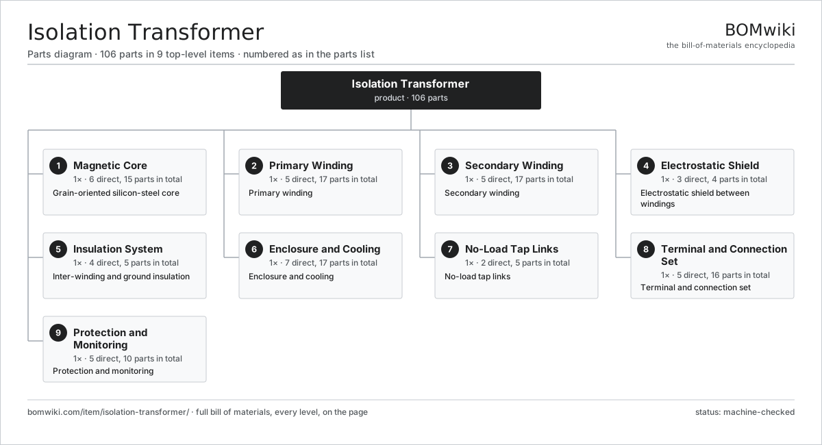
| # | Part | Qty | What it does |
|---|---|---|---|
| 1 | Magnetic Core 6 parts | 1× | Grain-oriented silicon-steel core |
| 2 | Primary Winding 5 parts | 1× | Primary winding |
| 3 | Secondary Winding 5 parts | 1× | Secondary winding |
| 4 | Electrostatic Shield 3 parts | 1× | Electrostatic shield between windings |
| 5 | Insulation System 4 parts | 1× | Inter-winding and ground insulation |
| 6 | Enclosure and Cooling 7 parts | 1× | Enclosure and cooling |
| 7 | No-Load Tap Links 2 parts | 1× | No-load tap links |
| 8 | Terminal and Connection Set 5 parts | 1× | Terminal and connection set |
| 9 | Protection and Monitoring 5 parts | 1× | Protection and monitoring |
3D model
No 3D model yet. Have a CAD file of this? Add a 3D model. STL renders right on this page; STEP, FreeCAD, and OpenSCAD sources are welcome too (openly licensed, like all 3D models on BOMwiki).
Build & assembly graph
expand / collapse · shared sub-assemblies converge · links to related products · est. labourTap an assembly to expand/collapse · tap a part to open it · use “Open page” for any node · drag to pan, scroll to zoom.
Bill of materials for Isolation Transformer
9 top-level lines · 51 rows shown · 106 parts total · indented to 3 levels| # | Item / sub-assembly | Part no. | Qty/assy | Ext. qty | Parts | Type |
|---|---|---|---|---|---|---|
| 1 | Magnetic Core 6 parts | isolation-transformer-core | 1× | 1 | 15 | assembly |
| 1.1 | GO Silicon-Steel Lamination | isolation-transformer-core-lamination | 1× | 1 | · | part |
| 1.2 | Core Limb | isolation-transformer-core-limb | 3× | 3 | · | part |
| 1.3 | Core Yoke | isolation-transformer-core-yoke | 2× | 2 | · | part |
| 1.4 | Core Clamping Frame | isolation-transformer-core-clamp | 4× | 4 | · | part |
| 1.5 | Core Banding | isolation-transformer-core-band | 4× | 4 | · | part |
| 1.6 | Core Ground Strap | isolation-transformer-core-ground-strap | 1× | 1 | · | part |
| 2 | Primary Winding 5 parts | isolation-transformer-primary-winding | 1× | 1 | 17 | assembly |
| 2.1 | Primary Copper Conductor | isolation-transformer-primary-conductor | 1× | 1 | · | part |
| 2.2 | Coil Former | isolation-transformer-coil-former | 1× | 1 | · | part |
| 2.3 | Inter-Layer Insulation | isolation-transformer-layer-insulation | 1× | 1 | · | part |
| 2.4 | Coil Lead | isolation-transformer-coil-lead | 2× | 2 | · | part |
| 2.5 | Coil Spacer | isolation-transformer-spacer-block | 12× | 12 | · | part |
| 3 | Secondary Winding 5 parts | isolation-transformer-secondary-winding | 1× | 1 | 17 | assembly |
| 3.1 | Secondary Copper Conductor | isolation-transformer-secondary-conductor | 1× | 1 | · | part |
| 3.2 | Coil Former | isolation-transformer-coil-former | 1× | 1 | · | part |
| 3.3 | Inter-Layer Insulation | isolation-transformer-layer-insulation | 1× | 1 | · | part |
| 3.4 | Coil Lead | isolation-transformer-coil-lead | 2× | 2 | · | part |
| 3.5 | Coil Spacer | isolation-transformer-spacer-block | 12× | 12 | · | part |
| 4 | Electrostatic Shield 3 parts | isolation-transformer-shield | 1× | 1 | 4 | assembly |
| 4.1 | Faraday Shield | isolation-transformer-faraday-shield | 1× | 1 | · | part |
| 4.2 | Shield Earth Lead | isolation-transformer-shield-lead | 1× | 1 | · | part |
| 4.3 | Shield Insulation | isolation-transformer-shield-insulation | 2× | 2 | · | part |
| 5 | Insulation System 4 parts | isolation-transformer-insulation | 1× | 1 | 5 | assembly |
| 5.1 | Inter-Winding Barrier | isolation-transformer-barrier-cylinder | 1× | 1 | · | part |
| 5.2 | End Insulation | isolation-transformer-end-insulation | 2× | 2 | · | part |
| 5.3 | Impregnation Varnish | isolation-transformer-impregnation-varnish | 1× | 1 | · | part |
| 5.4 | Insulating Tape | isolation-transformer-insulation-tape | 1× | 1 | · | part |
| 6 | Enclosure and Cooling 7 parts | isolation-transformer-enclosure | 1× | 1 | 17 | assembly |
| 6.1 | Enclosure Housing | isolation-transformer-housing | 1× | 1 | · | part |
| 6.2 | Mounting Base | isolation-transformer-mounting-base | 1× | 1 | · | part |
| 6.3 | Ventilation Louver | isolation-transformer-vent-louver | 4× | 4 | · | part |
| 6.4 | Cooling Fan | isolation-transformer-cooling-fan | 2× | 2 | · | part |
| 6.5 | Sheet Metal Panel | sheet-panel | 4× | 4 | · | part |
| 6.6 | Fastener Set | fastener-set | 1× | 1 | · | part |
| 6.7 | Coil Spring | coil-spring | 4× | 4 | · | part |
| 7 | No-Load Tap Links 2 parts | isolation-transformer-taps | 1× | 1 | 5 | assembly |
| 7.1 | Tap Link | isolation-transformer-tap-link | 4× | 4 | · | part |
| 7.2 | Tap Terminal Board | isolation-transformer-tap-board | 1× | 1 | · | part |
| 8 | Terminal and Connection Set 5 parts | isolation-transformer-terminals | 1× | 1 | 16 | assembly |
| 8.1 | Power Terminal Block | isolation-transformer-terminal-block | 6× | 6 | · | part |
| 8.2 | Cable Gland | isolation-transformer-cable-gland | 4× | 4 | · | part |
| 8.3 | Earth Terminal | isolation-transformer-earth-terminal | 1× | 1 | · | part |
| 8.4 | Connector | connector | 4× | 4 | · | part |
| 8.5 | Wire Bundle | wire-bundle | 1× | 1 | · | part |
| 9 | Protection and Monitoring 5 parts | isolation-transformer-protection | 1× | 1 | 10 | assembly |
| 9.1 | Thermal Cutout | isolation-transformer-thermal-cutout | 1× | 1 | · | part |
| 9.2 | Winding Temperature Sensor | isolation-transformer-temperature-sensor | 2× | 2 | · | part |
| 9.3 | Protective Fuse | isolation-transformer-fuse | 4× | 4 | · | part |
| 9.4 | Line Insulation Monitor | isolation-transformer-insulation-monitor | 1× | 1 | · | part |
| 9.5 | Relay | relay | 2× | 2 | · | part |
Related products
same domain, ranked by shared parts Automatic Voltage Regulator
83 parts · shares 3 with this page
Bottom Ash Handling System
1,782 parts · shares 3 with this page
Automatic Voltage Regulator
83 parts · shares 3 with this page
Bottom Ash Handling System
1,782 parts · shares 3 with this page
 Combined Heat and Power Unit
522 parts · shares 3 with this page
Combined Heat and Power Unit
522 parts · shares 3 with this page
 Distribution Ring Main Unit
443 parts · shares 3 with this page
Distribution Ring Main Unit
443 parts · shares 3 with this page
 Geothermal Wellhead
274 parts · shares 3 with this page
Geothermal Wellhead
274 parts · shares 3 with this page
 Large Power Transformer
1,844 parts · shares 3 with this page
Large Power Transformer
1,844 parts · shares 3 with this page
Sourcing: possible vendors
Browse the supplier directory → Prices, MOQ, and lead times are algorithmic estimates, not quotes, and not claims about these companies. Company mappings are curated by keyword; est. price band $5k–$50M. How estimates work| Vendor | HQ | Specialty | MOQ | Lead time |
|---|---|---|---|---|
| gevernova.com ↗ | Cambridge, US | Power generation | made to order | 20–40 wks |
| siemens-energy.com ↗ | Munich, DE | Power & grid | made to order | 20–40 wks |
| hitachienergy.com ↗ | Zurich, CH | Grid & transformers | made to order | 20–40 wks |
|
🇨🇭ABB
abb.com ↗
|
Zurich, CH | Electrification & automation | made to order | 20–40 wks |
| se.com ↗ | Rueil-Malmaison, FR | Electrical & automation | made to order | 20–40 wks |
876-word article