Gas Engine Genset
ProductOverview
A gas engine genset converts the chemical energy in natural gas into electrical power through a reciprocating internal combustion engine coupled to a synchronous alternator. The unit sits at the centre of distributed generation: it runs continuously to supply baseload power on a factory site, follows the grid as a peaking unit, or backs up a campus during outages. In a combined heat and power installation the same machine also supplies hot water or steam recovered from the Cooling System and the Exhaust System, which lifts the total fuel-to-useful-energy ratio toward 90 percent.
The engine described here is a lean-burn V20, 20 cylinders in a 70 degree vee, with a 170 mm bore and 195 mm stroke giving 88.5 litres of displacement. It runs at a fixed 1500 rpm for 50 Hz grids or 1800 rpm for 60 Hz grids, producing between 1.5 and 4.0 MW depending on the rating and gas quality. Electrical efficiency at the terminals is 43 to 45 percent on a lower-heating-value basis, which is high for a reciprocating machine and comes from high brake mean effective pressure, two-stage charge-air cooling, and prechamber ignition of a very lean mixture.
Engine block and power train
The Engine Block Assembly is the load-bearing core. A cast iron Cylinder Block carries integral water jackets and bore liners, and a forged Crankshaft runs in eleven tri-metal Main Bearing Shell shells. Each cylinder has its own Piston Assembly with a gallery-cooled crown, riding on a forged Connecting Rod with a cracked big-end cap. A Torsional Vibration Damper on the free end of the crank keeps torsional stress within limits across the firing orders of a long twenty-cylinder shaft.
Each cylinder carries an individual Cylinder Head Assembly rather than a shared casting, which simplifies maintenance and improves cooling around the valve bridges. The head holds two intake and two exhaust valves and an unscavenged Prechamber. The prechamber is central to lean-burn operation: a small charge of richer mixture is ignited in the chamber, and the resulting jets of flame light the very lean main charge in the cylinder, which a single spark plug could not reliably ignite on its own.
Fuel, air and combustion
Lean-burn combustion means running with far more air than the chemistry strictly needs, typically a lambda around 1.6 to 1.8. The excess air lowers peak flame temperature, which is what keeps nitrogen oxide formation down without a reduction catalyst. Holding that air-fuel ratio steady is the job of the Gas Fuel System. Fuel gas passes through a Gas Train of double block-and-bleed safety shutoff valves, then a Zero-Pressure Regulator delivers it to the Gas Mixer, which draws gas in proportion to air flow through a fixed venturi. Per-cylinder Fuel Admission Valve units trim individual cylinders for balanced combustion, and the Lambda Controller closes the loop on the wideband oxygen sensors in the exhaust.
Lean mixtures need a lot of air, so the Air Charging System system is sized generously. The Turbocharger compresses combustion air, a two-stage Charge-Air Intercooler cools it to raise density and control knock margin, and a Wastegate trims boost so the engine holds 18 to 22 bar BMEP without detonation. Gas quality matters here: the engine needs a methane number of at least 70 for full rating, because low methane number fuels such as those rich in propane and butane are far more prone to knock and force the controls to retard timing and derate.
Ignition and electrical generation
The Ignition System fires each prechamber through a dedicated Ignition Coil and a Spark Plug rated for the high cylinder pressures and electrode erosion of continuous lean-burn duty. The Ignition Control Module reads crank and cam position and sequences the coils, advancing or retarding timing as the lambda controller and knock logic demand. Prechamber plugs are a wear item and are tracked closely in the maintenance schedule.
Engine torque drives the Alternator through a flexible disc Flexible Coupling. It is a brushless synchronous machine built around a shared Stator Assembly and Rotor Assembly. A shaft-mounted Exciter feeds the main field through a rotating rectifier, and the Automatic Voltage Regulator regulates excitation to hold 6.6 kV or 11 kV terminal voltage at 0.8 power factor through load steps. Output leaves through a terminal box fitted with current transformers for metering and protection.
Heat rejection and lubrication
Roughly half the fuel energy that does not become electricity leaves as heat, split between coolant and exhaust. The Cooling System runs two circuits: a high-temperature jacket loop and a low-temperature loop for the intercooler and oil cooler, each with its own pump and thermostat, rejecting heat through a remote Radiator or feeding a CHP heat exchanger. The Lubricating Oil System supplies filtered, cooled oil through an engine-driven Oil Pump, and an electric Prelube Pump pressurises the galleries before cranking so the bearings never run dry on start.
Controls, exhaust treatment and packaging
The Control Panel holds the Engine Controller for speed governing and safety shutdowns, a Synchronizer that matches voltage, frequency and phase before closing the Main Circuit Breaker, and a protection relay covering over-current, reverse power and earth faults. Exhaust passes through an Oxidation Catalyst that cleans up carbon monoxide and formaldehyde, then a Exhaust Silencer that brings noise to residential limits. The whole machine sits on a welded Base Frame isolated from its foundation by anti-vibration mounts, with starting batteries and starter motors packaged on the skid for a self-contained 38 to 55 tonne unit.
Gas Engine Genset parts and their functions
10 top-level parts · 675 parts in total · full bill of materials below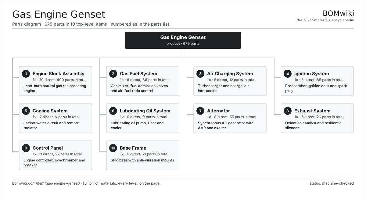
| # | Part | Qty | What it does |
|---|---|---|---|
| 1 | Engine Block Assembly 10 parts | 1× | Lean-burn natural gas reciprocating engine |
| 2 | Gas Fuel System 6 parts | 1× | Gas mixer, fuel admission valves and air-fuel ratio control |
| 3 | Air Charging System 5 parts | 1× | Turbocharger and charge-air intercooler |
| 4 | Ignition System 5 parts | 1× | Prechamber ignition coils and spark plugs |
| 5 | Cooling System 7 parts | 1× | Jacket water circuit and remote radiator |
| 6 | Lubricating Oil System 6 parts | 1× | Lubricating oil pump, filter and cooler |
| 7 | Alternator 8 parts | 1× | Synchronous AC generator with AVR and exciter |
| 8 | Exhaust System 5 parts | 1× | Oxidation catalyst and residential silencer |
| 9 | Control Panel 8 parts | 1× | Engine controller, synchronizer and breaker |
| 10 | Base Frame 6 parts | 1× | Skid base with anti-vibration mounts |
3D model
No 3D model yet. Have a CAD file of this? Add a 3D model. STL renders right on this page; STEP, FreeCAD, and OpenSCAD sources are welcome too (openly licensed, like all 3D models on BOMwiki).
Build & assembly graph
expand / collapse · shared sub-assemblies converge · links to related products · est. labourTap an assembly to expand/collapse · tap a part to open it · use “Open page” for any node · drag to pan, scroll to zoom.
Bill of materials for Gas Engine Genset
10 top-level lines · 126 rows shown · 675 parts total · indented to 3 levels| # | Item / sub-assembly | Part no. | Qty/assy | Ext. qty | Parts | Type |
|---|---|---|---|---|---|---|
| 1 | Engine Block Assembly 10 parts | gas-engine-genset-engine-block | 1× | 1 | 400 | assembly |
| 1.1 | Cylinder Block | gas-engine-genset-cylinder-block | 1× | 1 | · | part |
| 1.2 | Crankshaft | gas-engine-genset-crankshaft | 1× | 1 | · | part |
| 1.3 | Main Bearing Shell | gas-engine-genset-main-bearing | 11× | 11 | · | part |
| 1.4 | Piston Assembly 3 parts | gas-engine-genset-piston-assembly | 20× | 20 | 3 | assembly |
| 1.4.1 | Piston | gas-engine-genset-piston | 1× | 20 | · | part |
| 1.4.2 | Piston Ring Set | gas-engine-genset-piston-ring-set | 1× | 20 | · | part |
| 1.4.3 | Gudgeon Pin | gas-engine-genset-gudgeon-pin | 1× | 20 | · | part |
| 1.5 | Connecting Rod | gas-engine-genset-connecting-rod | 20× | 20 | · | part |
| 1.6 | Cylinder Head Assembly 7 parts | gas-engine-genset-cylinder-head | 20× | 20 | 15 | assembly |
| 1.6.1 | Head Casting | gas-engine-genset-head-casting | 1× | 20 | · | part |
| 1.6.2 | Prechamber | gas-engine-genset-prechamber | 1× | 20 | · | part |
| 1.6.3 | Intake Valve | gas-engine-genset-intake-valve | 2× | 40 | · | part |
| 1.6.4 | Exhaust Valve | gas-engine-genset-exhaust-valve | 2× | 40 | · | part |
| 1.6.5 | Valve Spring | gas-engine-genset-valve-spring | 4× | 80 | · | part |
| 1.6.6 | Rocker Arm | gas-engine-genset-rocker-arm | 4× | 80 | · | part |
| 1.6.7 | O-Ring Set | oring-set | 1× | 20 | · | part |
| 1.7 | Flywheel | gas-engine-genset-flywheel | 1× | 1 | · | part |
| 1.8 | Torsional Vibration Damper | gas-engine-genset-vibration-damper | 1× | 1 | · | part |
| 1.9 | Oil Pan | gas-engine-genset-oil-pan | 1× | 1 | · | part |
| 1.10 | Fastener Set | fastener-set | 4× | 4 | · | part |
| 2 | Gas Fuel System 6 parts | gas-engine-genset-fuel-system | 1× | 1 | 36 | assembly |
| 2.1 | Gas Train 4 parts | gas-engine-genset-gas-train | 1× | 1 | 6 | assembly |
| 2.1.1 | Safety Shutoff Valve | gas-engine-genset-safety-shutoff-valve | 2× | 2 | · | part |
| 2.1.2 | Gas Filter | gas-engine-genset-gas-filter | 1× | 1 | · | part |
| 2.1.3 | Pressure Sensor | pressure-sensor | 2× | 2 | · | part |
| 2.1.4 | Vent Valve | gas-engine-genset-vent-valve | 1× | 1 | · | part |
| 2.2 | Zero-Pressure Regulator | gas-engine-genset-zero-pressure-regulator | 1× | 1 | · | part |
| 2.3 | Gas Mixer | gas-engine-genset-gas-mixer | 1× | 1 | · | part |
| 2.4 | Throttle Actuator | gas-engine-genset-throttle-actuator | 1× | 1 | · | part |
| 2.5 | Fuel Admission Valve | gas-engine-genset-fuel-admission-valve | 20× | 20 | · | part |
| 2.6 | Lambda Controller 5 parts | gas-engine-genset-lambda-controller | 1× | 1 | 7 | assembly |
| 2.6.1 | Lambda Sensor | gas-engine-genset-lambda-sensor | 2× | 2 | · | part |
| 2.6.2 | Bare PCB | pcb-bare | 1× | 1 | · | part |
| 2.6.3 | Microcontroller | mcu | 1× | 1 | · | part |
| 2.6.4 | SMD Passive (R/C/L) | smd-passives | 1× | 1 | · | part |
| 2.6.5 | Connector | connector | 2× | 2 | · | part |
| 3 | Air Charging System 5 parts | gas-engine-genset-air-charging | 1× | 1 | 12 | assembly |
| 3.1 | Turbocharger 5 parts | gas-engine-genset-turbocharger | 1× | 1 | 7 | assembly |
| 3.1.1 | Turbine Wheel | gas-engine-genset-turbine-wheel | 1× | 1 | · | part |
| 3.1.2 | Compressor Wheel | gas-engine-genset-compressor-wheel | 1× | 1 | · | part |
| 3.1.3 | Ball Bearing | ball-bearing | 2× | 2 | · | part |
| 3.1.4 | Turbocharger Housing | gas-engine-genset-turbo-housing | 1× | 1 | · | part |
| 3.1.5 | Oil Seal | oil-seal | 2× | 2 | · | part |
| 3.2 | Charge-Air Intercooler | gas-engine-genset-intercooler | 1× | 1 | · | part |
| 3.3 | Wastegate | gas-engine-genset-wastegate | 1× | 1 | · | part |
| 3.4 | Air Filter | gas-engine-genset-air-filter | 1× | 1 | · | part |
| 3.5 | Intake Manifold | gas-engine-genset-intake-manifold | 2× | 2 | · | part |
| 4 | Ignition System 5 parts | gas-engine-genset-ignition-system | 1× | 1 | 85 | assembly |
| 4.1 | Ignition Control Module 5 parts | gas-engine-genset-ignition-module | 1× | 1 | 5 | assembly |
| 4.1.1 | Bare PCB | pcb-bare | 1× | 1 | · | part |
| 4.1.2 | Microcontroller | mcu | 1× | 1 | · | part |
| 4.1.3 | SMD Passive (R/C/L) | smd-passives | 1× | 1 | · | part |
| 4.1.4 | Crankshaft Position Sensor | gas-engine-genset-crank-sensor | 1× | 1 | · | part |
| 4.1.5 | Camshaft Position Sensor | gas-engine-genset-cam-sensor | 1× | 1 | · | part |
| 4.2 | Ignition Coil | gas-engine-genset-ignition-coil | 20× | 20 | · | part |
| 4.3 | Spark Plug | gas-engine-genset-spark-plug | 20× | 20 | · | part |
| 4.4 | High-Tension Lead | gas-engine-genset-ht-lead | 20× | 20 | · | part |
| 4.5 | Connector | connector | 20× | 20 | · | part |
| 5 | Cooling System 7 parts | gas-engine-genset-cooling-system | 1× | 1 | 9 | assembly |
| 5.1 | Jacket Water Pump | gas-engine-genset-jacket-water-pump | 1× | 1 | · | part |
| 5.2 | Auxiliary Water Pump | gas-engine-genset-aux-water-pump | 1× | 1 | · | part |
| 5.3 | Thermostat | gas-engine-genset-thermostat | 2× | 2 | · | part |
| 5.4 | Radiator | gas-engine-genset-radiator | 1× | 1 | · | part |
| 5.5 | Radiator Fan | gas-engine-genset-radiator-fan | 2× | 2 | · | part |
| 5.6 | Expansion Tank | gas-engine-genset-expansion-tank | 1× | 1 | · | part |
| 5.7 | Drive Belt | drive-belt | 1× | 1 | · | part |
| 6 | Lubricating Oil System 6 parts | gas-engine-genset-lube-system | 1× | 1 | 9 | assembly |
| 6.1 | Oil Pump 3 parts | gas-engine-genset-oil-pump | 1× | 1 | 3 | assembly |
| 6.1.1 | Helical Gear Pair | gear-pair | 1× | 1 | · | part |
| 6.1.2 | Oil Pump Body | gas-engine-genset-pump-body | 1× | 1 | · | part |
| 6.1.3 | Oil Seal | oil-seal | 1× | 1 | · | part |
| 6.2 | Oil Cooler | gas-engine-genset-oil-cooler | 1× | 1 | · | part |
| 6.3 | Oil Filter | gas-engine-genset-oil-filter | 2× | 2 | · | part |
| 6.4 | Prelube Pump | gas-engine-genset-prelube-pump | 1× | 1 | · | part |
| 6.5 | Oil Pressure Relief Valve | gas-engine-genset-oil-pressure-relief | 1× | 1 | · | part |
| 6.6 | Pressure Sensor | pressure-sensor | 1× | 1 | · | part |
| 7 | Alternator 8 parts | gas-engine-genset-alternator | 1× | 1 | 55 | assembly |
| 7.1 | Stator Assembly 3 parts | stator-assembly | 1× | 1 | 3 | assembly |
| 7.1.1 | Stator Core (laminations) | stator-core | 1× | 1 | · | part |
| 7.1.2 | Copper Winding | copper-winding | 1× | 1 | · | part |
| 7.1.3 | Slot Insulation | stator-insulation | 1× | 1 | · | part |
| 7.2 | Rotor Assembly 4 parts | rotor-assembly | 1× | 1 | 19 | assembly |
| 7.2.1 | Rotor Shaft | rotor-shaft | 1× | 1 | · | part |
| 7.2.2 | Rotor Core | rotor-core | 1× | 1 | · | part |
| 7.2.3 | Neodymium Magnet | neodymium-magnet | 16× | 16 | · | part |
| 7.2.4 | Ball Bearing | ball-bearing | 1× | 1 | · | part |
| 7.3 | Exciter 3 parts | gas-engine-genset-exciter | 1× | 1 | 23 | assembly |
| 7.3.1 | Stator Assembly 3 parts + deeper › | stator-assembly | 1× | 1 | 3 | assembly |
| 7.3.2 | Rotor Assembly 4 parts + deeper › | rotor-assembly | 1× | 1 | 19 | assembly |
| 7.3.3 | Rotating Rectifier | gas-engine-genset-rotating-rectifier | 1× | 1 | · | part |
| 7.4 | Automatic Voltage Regulator 4 parts | gas-engine-genset-avr | 1× | 1 | 5 | assembly |
| 7.4.1 | Bare PCB | pcb-bare | 1× | 1 | · | part |
| 7.4.2 | Microcontroller | mcu | 1× | 1 | · | part |
| 7.4.3 | SMD Passive (R/C/L) | smd-passives | 1× | 1 | · | part |
| 7.4.4 | Connector | connector | 2× | 2 | · | part |
| 7.5 | Ball Bearing | ball-bearing | 2× | 2 | · | part |
| 7.6 | Flexible Coupling | gas-engine-genset-coupling | 1× | 1 | · | part |
| 7.7 | Alternator Frame | gas-engine-genset-alternator-frame | 1× | 1 | · | part |
| 7.8 | Terminal Box | gas-engine-genset-terminal-box | 1× | 1 | · | part |
| 8 | Exhaust System 5 parts | gas-engine-genset-exhaust-system | 1× | 1 | 26 | assembly |
| 8.1 | Exhaust Manifold | gas-engine-genset-exhaust-manifold | 2× | 2 | · | part |
| 8.2 | Oxidation Catalyst | gas-engine-genset-oxidation-catalyst | 1× | 1 | · | part |
| 8.3 | Exhaust Silencer | gas-engine-genset-silencer | 1× | 1 | · | part |
| 8.4 | Exhaust Bellows | gas-engine-genset-bellows | 2× | 2 | · | part |
| 8.5 | Exhaust Thermocouple | gas-engine-genset-exhaust-thermocouple | 20× | 20 | · | part |
| 9 | Control Panel 8 parts | gas-engine-genset-control-panel | 1× | 1 | 22 | assembly |
| 9.1 | Engine Controller 4 parts | gas-engine-genset-engine-controller | 1× | 1 | 8 | assembly |
| 9.1.1 | Bare PCB | pcb-bare | 1× | 1 | · | part |
| 9.1.2 | Microcontroller | mcu | 2× | 2 | · | part |
| 9.1.3 | SMD Passive (R/C/L) | smd-passives | 1× | 1 | · | part |
| 9.1.4 | Connector | connector | 4× | 4 | · | part |
| 9.2 | Synchronizer | gas-engine-genset-synchronizer | 1× | 1 | · | part |
| 9.3 | Protection Relay | gas-engine-genset-protection-relay | 1× | 1 | · | part |
| 9.4 | Main Circuit Breaker | gas-engine-genset-main-breaker | 1× | 1 | · | part |
| 9.5 | LCD Panel | lcd-panel | 1× | 1 | · | part |
| 9.6 | Power Supply | power-supply | 1× | 1 | · | part |
| 9.7 | Relay | relay | 8× | 8 | · | part |
| 9.8 | Wire Bundle | wire-bundle | 1× | 1 | · | part |
| 10 | Base Frame 6 parts | gas-engine-genset-base-frame | 1× | 1 | 21 | assembly |
| 10.1 | Base Skid | gas-engine-genset-skid | 1× | 1 | · | part |
| 10.2 | Anti-Vibration Mount | gas-engine-genset-av-mount | 8× | 8 | · | part |
| 10.3 | Sheet Metal Panel | sheet-panel | 6× | 6 | · | part |
| 10.4 | Starting Battery | gas-engine-genset-battery | 2× | 2 | · | part |
| 10.5 | Starter Motor | gas-engine-genset-starter-motor | 2× | 2 | · | part |
| 10.6 | Fastener Set | fastener-set | 2× | 2 | · | part |
Related products
same domain, ranked by shared parts Flue Gas Desulfurization Scrubber
531 parts · shares 8 with this page
Bottom Ash Handling System
1,782 parts · shares 17 with this page
Flue Gas Desulfurization Scrubber
531 parts · shares 8 with this page
Bottom Ash Handling System
1,782 parts · shares 17 with this page
 Combined Heat and Power Unit
522 parts · shares 17 with this page
Combined Heat and Power Unit
522 parts · shares 17 with this page
 SCR NOx Reduction Unit
569 parts · shares 17 with this page
SCR NOx Reduction Unit
569 parts · shares 17 with this page
 Gas-Insulated Switchgear
281 parts · shares 16 with this page
Gas-Insulated Switchgear
281 parts · shares 16 with this page
Sourcing: possible vendors
Browse the supplier directory → Prices, MOQ, and lead times are algorithmic estimates, not quotes, and not claims about these companies. Company mappings are curated by keyword; est. price band $5k–$50M. How estimates work| Vendor | HQ | Specialty | MOQ | Lead time |
|---|---|---|---|---|
| gevernova.com ↗ | Cambridge, US | Power generation | made to order | 20–40 wks |
| siemens-energy.com ↗ | Munich, DE | Power & grid | made to order | 20–40 wks |
| hitachienergy.com ↗ | Zurich, CH | Grid & transformers | made to order | 20–40 wks |
|
🇨🇭ABB
abb.com ↗
|
Zurich, CH | Electrification & automation | made to order | 20–40 wks |
| se.com ↗ | Rueil-Malmaison, FR | Electrical & automation | made to order | 20–40 wks |
1,053-word article