Landfill Gas Blower Skid
ProductOverview
A landfill gas blower skid is the machine at the heart of a landfill gas collection system. Decomposing waste gives off gas, but that gas will not flow on its own from the buried wells to where it is burned or used. The blower skid pulls a controlled vacuum on the network of extraction wells, draws the gas through the field header, removes the water it carries, and pushes it on at the pressure a flare or a gas engine needs. By holding a steady vacuum it keeps the gas moving toward the wells rather than escaping through the cap, while not pulling so hard that it draws air into the landfill, which would stop the methane-forming bacteria and risk a fire underground.
Gas is moved by the Gas Blower and dried by the Condensate Knockout. It is routed through the Process Piping, the speed and safety are run by the Control Panel, the Instrumentation sensors report conditions, and it all sits on the Skid Frame and Enclosure.
The blower
The Gas Blower makes the suction that drives the whole system. An explosion-rated Drive Motor turns an Impeller inside a gas-tight Volute Casing, with the gas drawn in under vacuum from the field and pushed out under slight pressure to the flare or engine. The shaft runs on Ball Bearing supports and is kept gas-tight by Oil Seal seals, joined to the motor by a flexible Motor Coupling. The whole blower sits on Vibration Isolator isolators so its vibration does not travel into the piping. Regenerative blowers suit lower flows and higher vacuums, while centrifugal units handle larger fields, and the wheel and motor are matched to the well-field flow and the vacuum it needs.
Removing the water
Landfill gas comes up warm and saturated with water, which would damage a blower and choke an engine, so the Condensate Knockout removes it. Gas slows down in the Knockout Vessel so the heavier liquid drops out, and a Mist Eliminator mesh pad catches the fine droplets that stay suspended. The collected water is handled automatically: a Level Switch starts the Condensate Pump when the vessel fills, and a Drain Valve lets the condensate out without letting gas escape. Dry gas protects everything downstream, which is why the knockout sits ahead of the blower on the suction side.
Process piping and safety
The Process Piping carries the gas through the skid and gives the operator the means to set and isolate flow. An Inlet Valve cuts the skid off from the field header for service, a Flow Control Valve trims the gas rate and the field vacuum, and a Check Valve on the discharge stops backflow from the flare or engine. The key safety device is the Flame Arrestor, which lets gas pass but blocks any flame from travelling back into the piping and the wells. The components are joined by welded Pipe Spool sections with Expansion Joint joints that absorb thermal movement and blower vibration.
Control and instruments
The Control Panel panel runs the skid and keeps the field balanced. A PLC with its Microcontroller and Bare PCB holds the vacuum setpoint and the safety logic, and a Variable Frequency Drive varies the blower speed so the field vacuum stays steady as the gas flow changes through the day and over the years. The panel runs on a Power Supply, drives Relay outputs through a Wire Bundle, shows status on a Operator HMI, and sits in a rated Panel Enclosure. The Instrumentation sensors feed it: a Flow Meter logs how much gas is extracted, Pressure Sensor units read the field vacuum and discharge pressure, a Temperature Sensor tracks the warm gas, and a Gas Analyzer reads methane and oxygen so an operator can tell if a well is starting to pull air.
Frame, enclosure, and use
Everything is built on the Skid Frame and Enclosure, a welded Base Frame sized so the complete skid lifts and sets as one unit, under a Weather Enclosure that protects it outdoors. Because the equipment handles flammable gas, the enclosure has Ventilation Fan to purge any leak and a Gas Detector that alarms and trips the skid if methane builds up inside, with a Fastener Set holding it together. In service the blower skid is the link between the well field and the burner: it usually feeds a Landfill Gas Flare for destruction, a gas engine for power, or both, with the flare taking any gas the engine cannot use. It is sized to the field flow, which declines over the life of a closed landfill, so the Variable Frequency Drive keeps the unit efficient as the gas tapers off across many years.
Landfill Gas Blower Skid parts and their functions
6 top-level parts · 51 parts in total · full bill of materials below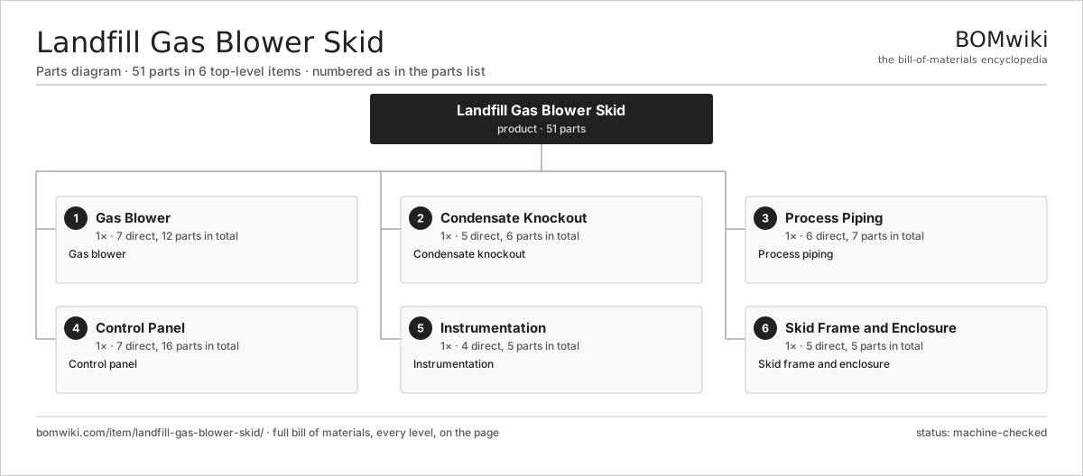
| # | Part | Qty | What it does |
|---|---|---|---|
| 1 | Gas Blower 7 parts | 1× | Gas blower |
| 2 | Condensate Knockout 5 parts | 1× | Condensate knockout |
| 3 | Process Piping 6 parts | 1× | Process piping |
| 4 | Control Panel 7 parts | 1× | Control panel |
| 5 | Instrumentation 4 parts | 1× | Instrumentation |
| 6 | Skid Frame and Enclosure 5 parts | 1× | Skid frame and enclosure |
3D model
No 3D model yet. Have a CAD file of this? Add a 3D model. STL renders right on this page; STEP, FreeCAD, and OpenSCAD sources are welcome too (openly licensed, like all 3D models on BOMwiki).
Build & assembly graph
expand / collapse · shared sub-assemblies converge · links to related products · est. labourTap an assembly to expand/collapse · tap a part to open it · use “Open page” for any node · drag to pan, scroll to zoom.
Bill of materials for Landfill Gas Blower Skid
6 top-level lines · 44 rows shown · 51 parts total · indented to 3 levels| # | Item / sub-assembly | Part no. | Qty/assy | Ext. qty | Parts | Type |
|---|---|---|---|---|---|---|
| 1 | Gas Blower 7 parts | landfill-gas-blower-skid-blower | 1× | 1 | 12 | assembly |
| 1.1 | Drive Motor | landfill-gas-blower-skid-blower-motor | 1× | 1 | · | part |
| 1.2 | Impeller | landfill-gas-blower-skid-impeller | 1× | 1 | · | part |
| 1.3 | Volute Casing | landfill-gas-blower-skid-volute | 1× | 1 | · | part |
| 1.4 | Ball Bearing | ball-bearing | 2× | 2 | · | part |
| 1.5 | Oil Seal | oil-seal | 2× | 2 | · | part |
| 1.6 | Motor Coupling | landfill-gas-blower-skid-coupling | 1× | 1 | · | part |
| 1.7 | Vibration Isolator | landfill-gas-blower-skid-vibration-iso | 4× | 4 | · | part |
| 2 | Condensate Knockout 5 parts | landfill-gas-blower-skid-knockout | 1× | 1 | 6 | assembly |
| 2.1 | Knockout Vessel | landfill-gas-blower-skid-knockout-vessel | 1× | 1 | · | part |
| 2.2 | Mist Eliminator | landfill-gas-blower-skid-demister | 1× | 1 | · | part |
| 2.3 | Condensate Pump | landfill-gas-blower-skid-drain-pump | 1× | 1 | · | part |
| 2.4 | Level Switch | landfill-gas-blower-skid-level-switch | 2× | 2 | · | part |
| 2.5 | Drain Valve | landfill-gas-blower-skid-drain-valve | 1× | 1 | · | part |
| 3 | Process Piping 6 parts | landfill-gas-blower-skid-piping | 1× | 1 | 7 | assembly |
| 3.1 | Inlet Valve | landfill-gas-blower-skid-inlet-valve | 1× | 1 | · | part |
| 3.2 | Flame Arrestor | landfill-gas-blower-skid-flame-arrestor | 1× | 1 | · | part |
| 3.3 | Check Valve | landfill-gas-blower-skid-check-valve | 1× | 1 | · | part |
| 3.4 | Flow Control Valve | landfill-gas-blower-skid-flow-valve | 1× | 1 | · | part |
| 3.5 | Pipe Spool | landfill-gas-blower-skid-pipe-spool | 1× | 1 | · | part |
| 3.6 | Expansion Joint | landfill-gas-blower-skid-expansion-joint | 2× | 2 | · | part |
| 4 | Control Panel 7 parts | landfill-gas-blower-skid-control | 1× | 1 | 16 | assembly |
| 4.1 | PLC 4 parts | landfill-gas-blower-skid-plc | 1× | 1 | 7 | assembly |
| 4.1.1 | Bare PCB | pcb-bare | 1× | 1 | · | part |
| 4.1.2 | Microcontroller | mcu | 1× | 1 | · | part |
| 4.1.3 | SMD Passive (R/C/L) | smd-passives | 1× | 1 | · | part |
| 4.1.4 | Connector | connector | 4× | 4 | · | part |
| 4.2 | Variable Frequency Drive | landfill-gas-blower-skid-vfd | 1× | 1 | · | part |
| 4.3 | Power Supply | power-supply | 1× | 1 | · | part |
| 4.4 | Operator HMI | landfill-gas-blower-skid-hmi | 1× | 1 | · | part |
| 4.5 | Relay | relay | 4× | 4 | · | part |
| 4.6 | Panel Enclosure | landfill-gas-blower-skid-panel-enclosure | 1× | 1 | · | part |
| 4.7 | Wire Bundle | wire-bundle | 1× | 1 | · | part |
| 5 | Instrumentation 4 parts | landfill-gas-blower-skid-instrument | 1× | 1 | 5 | assembly |
| 5.1 | Flow Meter | landfill-gas-blower-skid-flow-meter | 1× | 1 | · | part |
| 5.2 | Pressure Sensor | pressure-sensor | 2× | 2 | · | part |
| 5.3 | Temperature Sensor | landfill-gas-blower-skid-temp-sensor | 1× | 1 | · | part |
| 5.4 | Gas Analyzer | landfill-gas-blower-skid-gas-analyzer | 1× | 1 | · | part |
| 6 | Skid Frame and Enclosure 5 parts | landfill-gas-blower-skid-frame | 1× | 1 | 5 | assembly |
| 6.1 | Base Frame | landfill-gas-blower-skid-base-frame | 1× | 1 | · | part |
| 6.2 | Weather Enclosure | landfill-gas-blower-skid-enclosure | 1× | 1 | · | part |
| 6.3 | Ventilation Fan | landfill-gas-blower-skid-ventilation | 1× | 1 | · | part |
| 6.4 | Gas Detector | landfill-gas-blower-skid-gas-detector | 1× | 1 | · | part |
| 6.5 | Fastener Set | fastener-set | 1× | 1 | · | part |
Related products
same domain, ranked by shared parts Coal Pulverizer Mill
313 parts · shares 5 with this page
Coal Pulverizer Mill
313 parts · shares 5 with this page
 Combined Heat and Power Unit
522 parts · shares 5 with this page
Containerized Diesel Genset
655 parts · shares 5 with this page
Combined Heat and Power Unit
522 parts · shares 5 with this page
Containerized Diesel Genset
655 parts · shares 5 with this page
 Electrostatic Precipitator
879 parts · shares 5 with this page
Electrostatic Precipitator
879 parts · shares 5 with this page
 Flue Gas Desulfurization Scrubber
531 parts · shares 5 with this page
Flue Gas Desulfurization Scrubber
531 parts · shares 5 with this page
Sourcing: possible vendors
Browse the supplier directory → Prices, MOQ, and lead times are algorithmic estimates, not quotes, and not claims about these companies. Company mappings are curated by keyword; est. price band $5k–$50M. How estimates work| Vendor | HQ | Specialty | MOQ | Lead time |
|---|---|---|---|---|
| gevernova.com ↗ | Cambridge, US | Power generation | made to order | 20–40 wks |
| siemens-energy.com ↗ | Munich, DE | Power & grid | made to order | 20–40 wks |
| hitachienergy.com ↗ | Zurich, CH | Grid & transformers | made to order | 20–40 wks |
|
🇨🇭ABB
abb.com ↗
|
Zurich, CH | Electrification & automation | made to order | 20–40 wks |
| se.com ↗ | Rueil-Malmaison, FR | Electrical & automation | made to order | 20–40 wks |
919-word article