Resistive Load Bank
ProductOverview
A resistive load bank is a device that draws a known, controllable electrical load so that a power source can be tested under real conditions without connecting it to a building or grid. It does this by converting the electricity into heat in a set of resistor elements and blowing that heat away with a fan. The most common use is to commission and exercise standby generators: a diesel or gas Towable Power Generator Trailer or a fixed set must be run at or near full output to prove it can carry load, to burn off the unburnt fuel and carbon that build up during light running, and to verify cooling and controls. A resistive bank loads the source at unity power factor, drawing real power only, which tests the engine and the generator's heat path directly.
The bank works as a chain. The source connects at the Power Input, passes through the Protection and Metering gear, and reaches the Step Switching contactors that connect groups of the Element Array. The Cooling System system forces air over the elements to carry the heat away, the Control Panel panel sets how much load is applied, and the Enclosure holds it all and routes the airflow.
The resistor elements
The Element Array is where the energy is actually absorbed. Each Resistor Element is a length of nichrome wire or ribbon, often finned to spread its surface, that turns current into heat in proportion to its resistance and the square of the current through it. Nichrome is chosen because it holds its resistance and resists oxidation while running red-hot. The elements sit in a steel Element Frame across the path of the cooling air, isolated by ceramic Standoff Insulator standoffs, and wired into switched groups through copper Bus Link bars to the Bank Terminal lugs. Grouping the elements into binary or graded sizes is what lets the bank make many distinct load values from a handful of switched circuits. The elements run hot enough to need constant airflow, so they are never energised without proven cooling.
Cooling
Because every watt drawn becomes a watt of heat, the Cooling System system is as important as the elements. A Cooling Blower driven by its Blower Motor forces a large volume of air through the Air Duct plenum and across the element rows, and a Discharge Hood sends the hot exhaust up and clear of people and equipment. The safety interlock here is the Airflow Switch, which must prove that air is actually moving before any load step is allowed to energise. If the fan fails or a louver is blocked while elements are live, they overheat in seconds, so the airflow proof and the over-temperature trips are the most important protections in the whole unit.
Switching and control
Load is applied in steps by the Step Switching gear. Large Step Contactor units connect coarse blocks of elements, and smaller Fine Contactor units add or drop small amounts for fine adjustment, all fed from the Contactor Bus. The combination lets the operator set load close to any target. The Control Panel panel commands those contactors. Its Load Controller reads the target, which the operator sets with Step Selectors step switches or sends through the Remote Port, and drives the contactors to match, showing the result on the LCD Panel. Automatic units run a stored profile, for example ramping a generator up in stages and holding each for a set time to log a full acceptance test without an operator at the panel.
Connection, protection, and metering
The source reaches the bank at the Power Input, either through bolted Input Lug connections for a fixed install or Cam-lock connectors for fast field hookup, feeding the Main Bus with the frame bonded through the Ground Bar. The Protection and Metering section guards the bank and measures the test: a Main Breaker isolates and trips on overcurrent, Element Fuses fuses clear a single shorted element without dropping the bank, Current Transformer transformers feed a Power Meter that reports voltage, current, power, and energy per phase, and Over-temp Sensor sensors trip the load if the elements run too hot. The whole assembly lives in the Enclosure, a Sheet Metal Panel cabinet on a welded Structural Frame with an Intake Louver for air and Lifting Eye points for craning.
Use and variants
Resistive load banks are standard equipment wherever generators must be proven and maintained: data centres, hospitals, telecom sites, ships, and rental fleets. They are used at commissioning to demonstrate full output, on a schedule to exercise standby sets and prevent the wet stacking that light running causes in diesel engines, and during fault finding to apply a known steady load. A purely resistive bank tests real power only, so where a generator and its automatic voltage regulator must be checked under a realistic mix of real and reactive load, a combined resistive and reactive bank adds inductive elements to pull the power factor down. Banks range from small portable units of a few hundred kilowatts to trailer-mounted megawatt units, and at high voltage they connect directly to medium-voltage switchgear. In every form the job is the same: provide a clean, adjustable, well-instrumented load so a source can be tested honestly.
Resistive Load Bank parts and their functions
7 top-level parts · 185 parts in total · full bill of materials below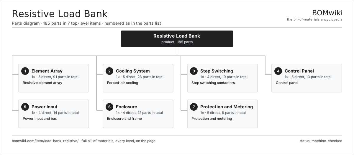
| # | Part | Qty | What it does |
|---|---|---|---|
| 1 | Element Array 5 parts | 1× | Resistive element array |
| 2 | Cooling System 5 parts | 1× | Forced-air cooling |
| 3 | Step Switching 4 parts | 1× | Step switching contactors |
| 4 | Control Panel 5 parts | 1× | Control panel |
| 5 | Power Input 4 parts | 1× | Power input and bus |
| 6 | Enclosure 4 parts | 1× | Enclosure and frame |
| 7 | Protection and Metering 5 parts | 1× | Protection and metering |
3D model
No 3D model yet. Have a CAD file of this? Add a 3D model. STL renders right on this page; STEP, FreeCAD, and OpenSCAD sources are welcome too (openly licensed, like all 3D models on BOMwiki).
Build & assembly graph
expand / collapse · shared sub-assemblies converge · links to related products · est. labourTap an assembly to expand/collapse · tap a part to open it · use “Open page” for any node · drag to pan, scroll to zoom.
Bill of materials for Resistive Load Bank
7 top-level lines · 46 rows shown · 185 parts total · indented to 3 levels| # | Item / sub-assembly | Part no. | Qty/assy | Ext. qty | Parts | Type |
|---|---|---|---|---|---|---|
| 1 | Element Array 5 parts | load-bank-resistive-element-array | 1× | 1 | 91 | assembly |
| 1.1 | Resistor Element | load-bank-resistive-element | 48× | 48 | · | part |
| 1.2 | Element Frame | load-bank-resistive-element-frame | 1× | 1 | · | part |
| 1.3 | Bus Link | load-bank-resistive-bus-link | 12× | 12 | · | part |
| 1.4 | Standoff Insulator | load-bank-resistive-insulator | 24× | 24 | · | part |
| 1.5 | Bank Terminal | load-bank-resistive-terminal | 6× | 6 | · | part |
| 2 | Cooling System 5 parts | load-bank-resistive-cooling | 1× | 1 | 28 | assembly |
| 2.1 | Cooling Blower | load-bank-resistive-blower | 1× | 1 | · | part |
| 2.2 | Blower Motor 3 parts | load-bank-resistive-blower-motor | 1× | 1 | 24 | assembly |
| 2.2.1 | Stator Assembly 3 parts + deeper › | stator-assembly | 1× | 1 | 3 | assembly |
| 2.2.2 | Rotor Assembly 4 parts + deeper › | rotor-assembly | 1× | 1 | 19 | assembly |
| 2.2.3 | Ball Bearing | ball-bearing | 2× | 2 | · | part |
| 2.3 | Air Duct | load-bank-resistive-air-duct | 1× | 1 | · | part |
| 2.4 | Airflow Switch | load-bank-resistive-airflow-switch | 1× | 1 | · | part |
| 2.5 | Discharge Hood | load-bank-resistive-discharge-hood | 1× | 1 | · | part |
| 3 | Step Switching 4 parts | load-bank-resistive-switching | 1× | 1 | 19 | assembly |
| 3.1 | Step Contactor | load-bank-resistive-step-contactor | 8× | 8 | · | part |
| 3.2 | Fine Contactor | load-bank-resistive-fine-contactor | 4× | 4 | · | part |
| 3.3 | Contactor Bus | load-bank-resistive-contactor-bus | 1× | 1 | · | part |
| 3.4 | Relay | relay | 6× | 6 | · | part |
| 4 | Control Panel 5 parts | load-bank-resistive-control | 1× | 1 | 13 | assembly |
| 4.1 | Load Controller 4 parts | load-bank-resistive-controller | 1× | 1 | 9 | assembly |
| 4.1.1 | Bare PCB | pcb-bare | 1× | 1 | · | part |
| 4.1.2 | Microcontroller | mcu | 1× | 1 | · | part |
| 4.1.3 | SMD Passive (R/C/L) | smd-passives | 1× | 1 | · | part |
| 4.1.4 | Connector | connector | 6× | 6 | · | part |
| 4.2 | LCD Panel | lcd-panel | 1× | 1 | · | part |
| 4.3 | Step Selectors | load-bank-resistive-load-pots | 1× | 1 | · | part |
| 4.4 | Remote Port | load-bank-resistive-remote-port | 1× | 1 | · | part |
| 4.5 | Power Supply | power-supply | 1× | 1 | · | part |
| 5 | Power Input 4 parts | load-bank-resistive-power-input | 1× | 1 | 14 | assembly |
| 5.1 | Input Lug | load-bank-resistive-input-lug | 6× | 6 | · | part |
| 5.2 | Cam-lock | load-bank-resistive-camlock | 6× | 6 | · | part |
| 5.3 | Main Bus | load-bank-resistive-main-bus | 1× | 1 | · | part |
| 5.4 | Ground Bar | load-bank-resistive-ground-bar | 1× | 1 | · | part |
| 6 | Enclosure 4 parts | load-bank-resistive-enclosure | 1× | 1 | 12 | assembly |
| 6.1 | Sheet Metal Panel | sheet-panel | 6× | 6 | · | part |
| 6.2 | Structural Frame | load-bank-resistive-frame | 1× | 1 | · | part |
| 6.3 | Intake Louver | load-bank-resistive-intake-louver | 1× | 1 | · | part |
| 6.4 | Lifting Eye | load-bank-resistive-lifting-eye | 4× | 4 | · | part |
| 7 | Protection and Metering 5 parts | load-bank-resistive-protection | 1× | 1 | 8 | assembly |
| 7.1 | Main Breaker | load-bank-resistive-main-breaker | 1× | 1 | · | part |
| 7.2 | Element Fuses | load-bank-resistive-fuse-set | 1× | 1 | · | part |
| 7.3 | Current Transformer | load-bank-resistive-ct | 3× | 3 | · | part |
| 7.4 | Power Meter | load-bank-resistive-meter | 1× | 1 | · | part |
| 7.5 | Over-temp Sensor | load-bank-resistive-overtemp | 2× | 2 | · | part |
Related products
same domain, ranked by shared parts Combined Heat and Power Unit
522 parts · shares 12 with this page
Containerized Diesel Genset
655 parts · shares 12 with this page
Gas Engine Genset
675 parts · shares 12 with this page
Combined Heat and Power Unit
522 parts · shares 12 with this page
Containerized Diesel Genset
655 parts · shares 12 with this page
Gas Engine Genset
675 parts · shares 12 with this page
 Gas-Insulated Switchgear
281 parts · shares 12 with this page
Gas-Insulated Switchgear
281 parts · shares 12 with this page
 Large Synchronous Generator
42,357 parts · shares 12 with this page
Large Synchronous Generator
42,357 parts · shares 12 with this page
Sourcing: possible vendors
Browse the supplier directory → Prices, MOQ, and lead times are algorithmic estimates, not quotes, and not claims about these companies. Company mappings are curated by keyword; est. price band $5k–$50M. How estimates work| Vendor | HQ | Specialty | MOQ | Lead time |
|---|---|---|---|---|
| gevernova.com ↗ | Cambridge, US | Power generation | made to order | 20–40 wks |
| siemens-energy.com ↗ | Munich, DE | Power & grid | made to order | 20–40 wks |
| hitachienergy.com ↗ | Zurich, CH | Grid & transformers | made to order | 20–40 wks |
|
🇨🇭ABB
abb.com ↗
|
Zurich, CH | Electrification & automation | made to order | 20–40 wks |
| se.com ↗ | Rueil-Malmaison, FR | Electrical & automation | made to order | 20–40 wks |
983-word article