Hydroelectric Generator
ProductOverview
A hydroelectric generator converts the potential energy of stored water into electricity. Water falling through a head of about 120 m drives a Francis reaction turbine, which spins a vertical synchronous generator producing 50 MW at 11 kV. The Francis runner suits medium-head sites and extracts energy from both the pressure and velocity of the water as it passes through. The unit runs at a fixed 300 RPM to deliver 50 Hz from its 20-pole generator.
Construction
Water enters through the Main Inlet Valve, the main shutoff that isolates the unit for maintenance, then passes into the Francis Water Turbine. The spiral casing distributes flow evenly around adjustable wicket gates, which meter water onto the runner; the runner's curved blades turn the flow's energy into shaft torque before the water exits down the draft tube.
The turbine shaft drives the Synchronous Generator, a vertical synchronous machine whose excited rotor poles induce three-phase voltage in the stator. Rotating mass is supported by the Guide & Thrust Bearing Assembly assembly, which carries both the radial guide bearings and the thrust bearing that bears the entire rotating weight plus hydraulic down-thrust. A Main Shaft Seal prevents water leakage where the shaft passes out of the turbine.
Output power is delivered through the Generator Busbar Terminal to the step-up transformer. Speed and load are regulated by the Hydraulic Governor, a hydraulic actuator that positions the wicket gates to hold frequency as load changes, supervised by the Control & Protection System protection system.
Auxiliaries keep the machine healthy: the Cooling Water System system removes heat from the generator and bearings, the Lubrication System supplies oil to the bearings, and the Foundation & Pit Liner pit liner anchors the unit in the powerhouse.
Hydroelectric Generator parts and their functions
11 top-level parts · 298 parts in total · full bill of materials below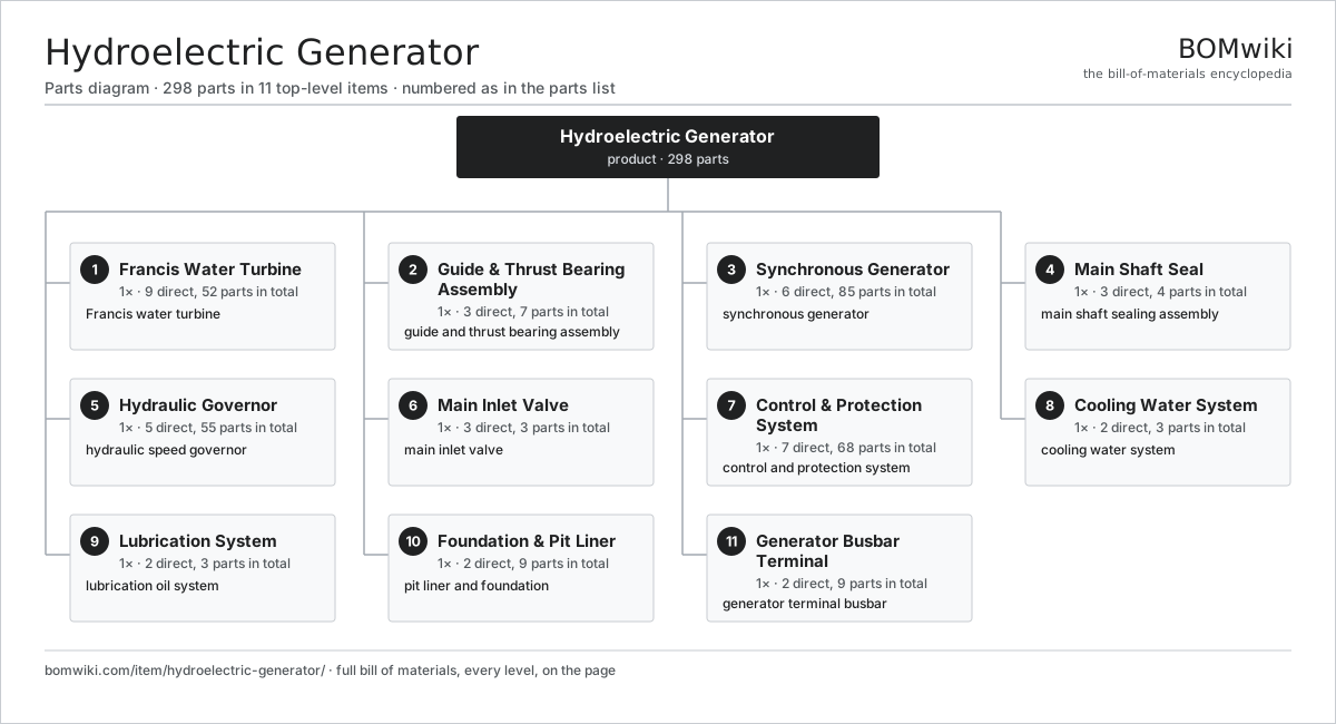
| # | Part | Qty | What it does |
|---|---|---|---|
| 1 | Francis Water Turbine 9 parts | 1× | Francis water turbine |
| 2 | Guide & Thrust Bearing Assembly 3 parts | 1× | guide and thrust bearing assembly |
| 3 | Synchronous Generator 6 parts | 1× | synchronous generator |
| 4 | Main Shaft Seal 3 parts | 1× | main shaft sealing assembly |
| 5 | Hydraulic Governor 5 parts | 1× | hydraulic speed governor |
| 6 | Main Inlet Valve 3 parts | 1× | main inlet valve |
| 7 | Control & Protection System 7 parts | 1× | control and protection system |
| 8 | Cooling Water System 2 parts | 1× | cooling water system |
| 9 | Lubrication System 2 parts | 1× | lubrication oil system |
| 10 | Foundation & Pit Liner 2 parts | 1× | pit liner and foundation |
| 11 | Generator Busbar Terminal 2 parts | 1× | generator terminal busbar |
3D model
No 3D model yet. Have a CAD file of this? Add a 3D model. STL renders right on this page; STEP, FreeCAD, and OpenSCAD sources are welcome too (openly licensed, like all 3D models on BOMwiki).
Build & assembly graph
expand / collapse · shared sub-assemblies converge · links to related products · est. labourTap an assembly to expand/collapse · tap a part to open it · use “Open page” for any node · drag to pan, scroll to zoom.
Bill of materials for Hydroelectric Generator
11 top-level lines · 74 rows shown · 298 parts total · indented to 3 levels| # | Item / sub-assembly | Part no. | Qty/assy | Ext. qty | Parts | Type |
|---|---|---|---|---|---|---|
| 1 | Francis Water Turbine 9 parts | hydroelectric-generator-turbine | 1× | 1 | 52 | assembly |
| 1.1 | Francis Runner | hydroelectric-generator-runner | 1× | 1 | · | part |
| 1.2 | Turbine Shaft | hydroelectric-generator-turbine-shaft | 1× | 1 | · | part |
| 1.3 | Wicket Gate Assembly 4 parts | hydroelectric-generator-wicket-gates | 1× | 1 | 42 | assembly |
| 1.3.1 | Guide Vane | hydroelectric-generator-guide-vane | 20× | 20 | · | part |
| 1.3.2 | Operating Ring | hydroelectric-generator-operating-ring | 1× | 1 | · | part |
| 1.3.3 | Ball Bearing | ball-bearing | 20× | 20 | · | part |
| 1.3.4 | O-Ring Set | oring-set | 1× | 1 | · | part |
| 1.4 | Spiral Casing | hydroelectric-generator-spiral-casing | 1× | 1 | · | part |
| 1.5 | Stay Ring | hydroelectric-generator-stay-ring | 1× | 1 | · | part |
| 1.6 | Head Cover | hydroelectric-generator-head-cover | 1× | 1 | · | part |
| 1.7 | Draft Tube | hydroelectric-generator-draft-tube | 1× | 1 | · | part |
| 1.8 | Wear Ring | hydroelectric-generator-wear-ring | 2× | 2 | · | part |
| 1.9 | O-Ring Set | oring-set | 2× | 2 | · | part |
| 2 | Guide & Thrust Bearing Assembly 3 parts | hydroelectric-generator-bearings | 1× | 1 | 7 | assembly |
| 2.1 | Ball Bearing | ball-bearing | 2× | 2 | · | part |
| 2.2 | Thrust Bearing | hydroelectric-generator-thrust-bearing | 1× | 1 | · | part |
| 2.3 | Oil Seal | oil-seal | 4× | 4 | · | part |
| 3 | Synchronous Generator 6 parts | hydroelectric-generator-generator | 1× | 1 | 85 | assembly |
| 3.1 | Rotor Assembly 4 parts | rotor-assembly | 1× | 1 | 19 | assembly |
| 3.1.1 | Rotor Shaft | rotor-shaft | 1× | 1 | · | part |
| 3.1.2 | Rotor Core | rotor-core | 1× | 1 | · | part |
| 3.1.3 | Neodymium Magnet | neodymium-magnet | 16× | 16 | · | part |
| 3.1.4 | Ball Bearing | ball-bearing | 1× | 1 | · | part |
| 3.2 | Field Pole | hydroelectric-generator-rotor-pole | 48× | 48 | · | part |
| 3.3 | Stator Assembly 3 parts | stator-assembly | 1× | 1 | 3 | assembly |
| 3.3.1 | Stator Core (laminations) | stator-core | 1× | 1 | · | part |
| 3.3.2 | Copper Winding | copper-winding | 1× | 1 | · | part |
| 3.3.3 | Slot Insulation | stator-insulation | 1× | 1 | · | part |
| 3.4 | Copper Winding | copper-winding | 6× | 6 | · | part |
| 3.5 | Exciter & AVR 2 parts | hydroelectric-generator-exciter | 1× | 1 | 3 | assembly |
| 3.5.1 | Bare PCB | pcb-bare | 2× | 2 | · | part |
| 3.5.2 | Microcontroller | mcu | 1× | 1 | · | part |
| 3.6 | Air Cooler | hydroelectric-generator-air-cooler | 6× | 6 | · | part |
| 4 | Main Shaft Seal 3 parts | hydroelectric-generator-shaft-seal | 1× | 1 | 4 | assembly |
| 4.1 | Shaft Seal Ring | hydroelectric-generator-seal-ring | 1× | 1 | · | part |
| 4.2 | Oil Seal | oil-seal | 2× | 2 | · | part |
| 4.3 | O-Ring Set | oring-set | 1× | 1 | · | part |
| 5 | Hydraulic Governor 5 parts | hydroelectric-generator-governor | 1× | 1 | 55 | assembly |
| 5.1 | Pressure Accumulator | hydroelectric-generator-accumulator | 1× | 1 | · | part |
| 5.2 | Governor Oil Pump 3 parts | hydroelectric-generator-gov-pump | 2× | 2 | 23 | assembly |
| 5.2.1 | Stator Assembly 3 parts + deeper › | stator-assembly | 1× | 2 | 3 | assembly |
| 5.2.2 | Rotor Assembly 4 parts + deeper › | rotor-assembly | 1× | 2 | 19 | assembly |
| 5.2.3 | Oil Seal | oil-seal | 1× | 2 | · | part |
| 5.3 | Governor Actuator | hydroelectric-generator-actuator | 1× | 1 | · | part |
| 5.4 | PID Governor Controller 3 parts | hydroelectric-generator-pid-controller | 1× | 1 | 5 | assembly |
| 5.4.1 | Bare PCB | pcb-bare | 2× | 2 | · | part |
| 5.4.2 | Microcontroller | mcu | 1× | 1 | · | part |
| 5.4.3 | Speed Sensor | hydroelectric-generator-speed-sensor | 2× | 2 | · | part |
| 5.5 | Pressure Sensor | pressure-sensor | 2× | 2 | · | part |
| 6 | Main Inlet Valve 3 parts | hydroelectric-generator-inlet-valve | 1× | 1 | 3 | assembly |
| 6.1 | Valve Body & Disc | hydroelectric-generator-valve-body | 1× | 1 | · | part |
| 6.2 | Valve Servomotor | hydroelectric-generator-valve-servomotor | 1× | 1 | · | part |
| 6.3 | O-Ring Set | oring-set | 1× | 1 | · | part |
| 7 | Control & Protection System 7 parts | hydroelectric-generator-control | 1× | 1 | 68 | assembly |
| 7.1 | Bare PCB | pcb-bare | 4× | 4 | · | part |
| 7.2 | Microcontroller | mcu | 2× | 2 | · | part |
| 7.3 | Pressure Sensor | pressure-sensor | 4× | 4 | · | part |
| 7.4 | Condition Sensor | hydroelectric-generator-condition-sensor | 16× | 16 | · | part |
| 7.5 | LCD Panel | lcd-panel | 1× | 1 | · | part |
| 7.6 | Wire Bundle | wire-bundle | 1× | 1 | · | part |
| 7.7 | Connector | connector | 40× | 40 | · | part |
| 8 | Cooling Water System 2 parts | hydroelectric-generator-cooling-water | 1× | 1 | 3 | assembly |
| 8.1 | Heat Exchanger | hydroelectric-generator-heat-exchanger | 1× | 1 | · | part |
| 8.2 | Pressure Sensor | pressure-sensor | 2× | 2 | · | part |
| 9 | Lubrication System 2 parts | hydroelectric-generator-lube-system | 1× | 1 | 3 | assembly |
| 9.1 | Lube Oil Pump | hydroelectric-generator-lube-pump | 2× | 2 | · | part |
| 9.2 | Oil Cooler & Filter | hydroelectric-generator-oil-conditioner | 1× | 1 | · | part |
| 10 | Foundation & Pit Liner 2 parts | hydroelectric-generator-foundation | 1× | 1 | 9 | assembly |
| 10.1 | Pit Liner | hydroelectric-generator-pit-liner | 1× | 1 | · | part |
| 10.2 | Fastener Set | fastener-set | 8× | 8 | · | part |
| 11 | Generator Busbar Terminal 2 parts | hydroelectric-generator-busbar | 1× | 1 | 9 | assembly |
| 11.1 | Busbar Conductor | hydroelectric-generator-busbar-conductor | 3× | 3 | · | part |
| 11.2 | Connector | connector | 6× | 6 | · | part |
Something wrong in this list? Report a problem with this BOM.
Related products
same domain, ranked by shared parts Combined Heat and Power Unit
522 parts · shares 14 with this page
Containerized Diesel Genset
655 parts · shares 14 with this page
Gas Engine Genset
675 parts · shares 14 with this page
 Large Synchronous Generator
42,357 parts · shares 14 with this page
 SCR NOx Reduction Unit
569 parts · shares 14 with this page
Sourcing: possible vendors
Browse the supplier directory → Prices, MOQ, and lead times are algorithmic estimates, not quotes, and not claims about these companies. Company mappings are curated by keyword; est. price band $5k–$50M. How estimates work| Vendor | HQ | Specialty | MOQ | Lead time |
|---|---|---|---|---|
| gevernova.com ↗ | Cambridge, US | Power generation | made to order | 20–40 wks |
| siemens-energy.com ↗ | Munich, DE | Power & grid | made to order | 20–40 wks |
| hitachienergy.com ↗ | Zurich, CH | Grid & transformers | made to order | 20–40 wks |
|
🇨🇭ABB
abb.com ↗
|
Zurich, CH | Electrification & automation | made to order | 20–40 wks |
| se.com ↗ | Rueil-Malmaison, FR | Electrical & automation | made to order | 20–40 wks |
298-word article