Fatigue Testing Rig
ProductAlso known as: Fatigue Testing Machine
Overview
A fatigue testing rig applies a load to a specimen over and over so the part can be run to failure and its fatigue life recorded. Static strength tells you the load a part survives once. Fatigue tells you how many times it survives a smaller repeated load before a crack starts and grows, which is what governs the life of most rotating and cyclically loaded hardware. The rig pulls and pushes the specimen between two grips while a load cell measures the force and a controller holds the chosen waveform, counting cycles until the specimen breaks or a target count is reached.
The most common form is the servo-hydraulic rig, which uses a hydraulic actuator and a servo valve to apply force across a wide range of amplitude and frequency. Force passes through the Load Frame that reacts it, the Servo-Hydraulic Actuator that applies it, the Load Cell that measures it, and the Specimen Grips and Fixtures that hold the specimen, all driven by the Dynamic Controller and fed by the Hydraulic Power Unit.
Load frame and reaction
The Load Frame gives the actuator something stiff to push against. A heavy Base Platen anchors the lower end, two Strain Column columns rise from it, and an adjustable Adjustable Crosshead spans the top to set the daylight for the specimen length. The columns are sized to stay well within their elastic range at full rated load, because any frame deflection adds to the measured stroke and corrupts a strain-controlled test. Once the crosshead is positioned, a Crosshead Lock clamps it to the columns so it cannot creep under millions of reversals, and Crosshead Lift Cylinder cylinders move it during setup. Four Isolation Mount feet keep the dynamic load from shaking the building floor.
Actuator and servo valve
The Servo-Hydraulic Actuator is a double-acting hydraulic cylinder. Oil pressure on either side of the Piston drives the Piston Rod in tension or compression, and the rod runs in Hydrostatic Bearing bearings that carry it on an oil film with almost no friction and no side play, which keeps the load axial over long runs. A Rod Seal Pack pack contains the oil where the rod leaves the Cylinder Body. The actuator is steered by a two-stage Servo Valve: a Torque Motor deflects the pilot stage from the controller current, the Pilot Spool drives the Main Spool, and the main spool meters oil to each chamber. A Actuator Accumulator Set mounted at the valve supplies the peak flow that fast cycling demands, which the pump cannot deliver on its own.
Hydraulic power unit
The Hydraulic Power Unit supplies the oil. A Variable Displacement Pump driven by the Pump Drive Motor holds system pressure between roughly 210 and 280 bar and varies its flow to match demand. Oil is drawn from the Oil Reservoir, passes through the Supply Manifold to the actuator, and is kept clean by Oil Filter filters, because the close clearances in the servo valve fail quickly on dirty oil. A System Accumulator absorbs pump pulsation and holds reserve volume for the whole rig. The pump and valve put heat into the oil, so an Oil Cooler with a finned Cooler Core and a Cooler Fan pulls that heat back out and holds the oil temperature steady, since oil viscosity drifts with temperature and the valve gain drifts with it.
Measuring load, stroke, and strain
The Load Cell sits in series with the specimen and reads the true applied force. Its Sensing Element is a machined flexure carrying Strain Gauge gauges in a bridge, and a Bridge Amplifier conditions the millivolt output for the controller. The element is made from a high-fatigue-strength steel so the cell itself does not fatigue before the specimens do. A Stroke LVDT inside the actuator reports rod position for stroke control, and for strain-controlled work a clip-on Extensometer measures elongation over a defined gauge length. The three signals, load, stroke, and strain, give the controller its choice of feedback variable and let the test record show the full hysteresis loop of each cycle.
Closed-loop control and cycle counting
The Dynamic Controller runs the test. Its Control Board closes the loop at several kilohertz, comparing the chosen feedback signal against the commanded waveform and correcting the valve every cycle. A Servo Valve Driver turns that command into the exact coil current the torque motor needs, and a Data Acquisition Board samples all channels in step so each cycle can be logged. Tests run in force control for stress-life work or in strain control for low-cycle work, and the controller can switch between them. A Cycle Counter tallies completed cycles and triggers the stop at the target count or when the load drops at specimen fracture, which marks the fatigue life.
Specimen handling and safety
The Specimen Grips and Fixtures hold the specimen on the load line. Hydraulic Wedge Grip wedge grips clamp harder as load rises, so the specimen does not slip through tension and compression reversals, and Grip Jaw inserts are changed to suit the specimen shape. An Alignment Fixture brings the upper and lower load lines coaxial, because any misalignment adds bending that shortens the measured life and scatters the results. Because a specimen releases stored energy when it breaks, the test runs inside a Safety Enclosure with Polycarbonate Window windows that contain fragments, Door Interlock interlocks that cut the actuator when a door opens, and a Emergency Stop that drops pressure at once. Most endurance runs go unattended for days, so the safety chain and the cooling matter as much as the measurement itself.
Fatigue Testing Rig parts and their functions
8 top-level parts · 412 parts in total · full bill of materials below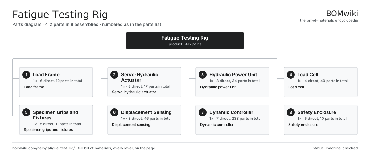
| # | Part | Qty | What it does |
|---|---|---|---|
| 1 | Load Frame 6 parts | 1× | Load frame |
| 2 | Servo-Hydraulic Actuator 8 parts | 1× | Servo-hydraulic actuator |
| 3 | Hydraulic Power Unit 8 parts | 1× | Hydraulic power unit |
| 4 | Load Cell 4 parts | 1× | Load cell |
| 5 | Specimen Grips and Fixtures 5 parts | 1× | Specimen grips and fixtures |
| 6 | Displacement Sensing 3 parts | 1× | Displacement sensing |
| 7 | Dynamic Controller 7 parts | 1× | Dynamic controller |
| 8 | Safety Enclosure 5 parts | 1× | Safety enclosure |
3D model
No 3D model yet. Have a CAD file of this? Add a 3D model — STL renders right on this page; STEP, FreeCAD, and OpenSCAD sources are welcome too (openly licensed, like all 3D models on BOMwiki).
Build & assembly graph
expand / collapse · shared sub-assemblies converge · links to related products · est. labourTap an assembly to expand/collapse · tap a part to open it · use “Open page” for any node · drag to pan, scroll to zoom.
Bill of materials for Fatigue Testing Rig
8 top-level lines · 87 rows shown · 412 parts total · indented to 3 levels| # | Item / sub-assembly | Part no. | Qty/assy | Ext. qty | Parts | Type |
|---|---|---|---|---|---|---|
| 1 | Load Frame 6 parts | fatigue-test-rig-load-frame | 1× | 1 | 12 | assembly |
| 1.1 | Base Platen | fatigue-test-rig-base-platen | 1× | 1 | · | part |
| 1.2 | Strain Column | fatigue-test-rig-column | 2× | 2 | · | part |
| 1.3 | Adjustable Crosshead | fatigue-test-rig-crosshead | 1× | 1 | · | part |
| 1.4 | Crosshead Lock | fatigue-test-rig-crosshead-lock | 2× | 2 | · | part |
| 1.5 | Crosshead Lift Cylinder | fatigue-test-rig-lift-cylinder | 2× | 2 | · | part |
| 1.6 | Isolation Mount | fatigue-test-rig-isolation-mount | 4× | 4 | · | part |
| 2 | Servo-Hydraulic Actuator 8 parts | fatigue-test-rig-actuator | 1× | 1 | 17 | assembly |
| 2.1 | Cylinder Body | fatigue-test-rig-cylinder-body | 1× | 1 | · | part |
| 2.2 | Piston Rod | fatigue-test-rig-piston-rod | 1× | 1 | · | part |
| 2.3 | Piston | fatigue-test-rig-piston | 1× | 1 | · | part |
| 2.4 | Hydrostatic Bearing | fatigue-test-rig-hydrostatic-bearing | 2× | 2 | · | part |
| 2.5 | Rod Seal Pack 2 parts | fatigue-test-rig-rod-seal | 1× | 1 | 3 | assembly |
| 2.5.1 | Oil Seal | oil-seal | 2× | 2 | · | part |
| 2.5.2 | O-Ring Set | oring-set | 1× | 1 | · | part |
| 2.6 | O-Ring Set | oring-set | 1× | 1 | · | part |
| 2.7 | Servo Valve 5 parts | fatigue-test-rig-servo-valve | 1× | 1 | 5 | assembly |
| 2.7.1 | Torque Motor | fatigue-test-rig-torque-motor | 1× | 1 | · | part |
| 2.7.2 | Pilot Spool | fatigue-test-rig-pilot-spool | 1× | 1 | · | part |
| 2.7.3 | Main Spool | fatigue-test-rig-main-spool | 1× | 1 | · | part |
| 2.7.4 | Valve Body | fatigue-test-rig-valve-body | 1× | 1 | · | part |
| 2.7.5 | O-Ring Set | oring-set | 1× | 1 | · | part |
| 2.8 | Actuator Accumulator Set 2 parts | fatigue-test-rig-accumulator-pair | 1× | 1 | 3 | assembly |
| 2.8.1 | Piston Accumulator | fatigue-test-rig-piston-accumulator | 2× | 2 | · | part |
| 2.8.2 | O-Ring Set | oring-set | 1× | 1 | · | part |
| 3 | Hydraulic Power Unit 8 parts | fatigue-test-rig-hpu | 1× | 1 | 34 | assembly |
| 3.1 | Variable Displacement Pump | fatigue-test-rig-pump | 1× | 1 | · | part |
| 3.2 | Pump Drive Motor 3 parts | fatigue-test-rig-pump-motor | 1× | 1 | 24 | assembly |
| 3.2.1 | Stator Assembly 3 parts + deeper › | stator-assembly | 1× | 1 | 3 | assembly |
| 3.2.2 | Rotor Assembly 4 parts + deeper › | rotor-assembly | 1× | 1 | 19 | assembly |
| 3.2.3 | Ball Bearing | ball-bearing | 2× | 2 | · | part |
| 3.3 | Oil Reservoir | fatigue-test-rig-reservoir | 1× | 1 | · | part |
| 3.4 | Supply Manifold | fatigue-test-rig-manifold | 1× | 1 | · | part |
| 3.5 | System Accumulator | fatigue-test-rig-hpu-accumulator | 1× | 1 | · | part |
| 3.6 | Oil Filter | fatigue-test-rig-filter | 2× | 2 | · | part |
| 3.7 | Oil Cooler 2 parts | fatigue-test-rig-oil-cooler | 1× | 1 | 2 | assembly |
| 3.7.1 | Cooler Core | fatigue-test-rig-cooler-core | 1× | 1 | · | part |
| 3.7.2 | Cooler Fan | fatigue-test-rig-cooler-fan | 1× | 1 | · | part |
| 3.8 | Pressure Sensor | pressure-sensor | 2× | 2 | · | part |
| 4 | Load Cell 4 parts | fatigue-test-rig-load-cell | 1× | 1 | 49 | assembly |
| 4.1 | Sensing Element | fatigue-test-rig-cell-element | 1× | 1 | · | part |
| 4.2 | Strain Gauge | fatigue-test-rig-strain-gauge | 4× | 4 | · | part |
| 4.3 | Bridge Amplifier 3 parts | fatigue-test-rig-cell-amp | 1× | 1 | 43 | assembly |
| 4.3.1 | Bare PCB | pcb-bare | 1× | 1 | · | part |
| 4.3.2 | SMD Passive (R/C/L) | smd-passives | 40× | 40 | · | part |
| 4.3.3 | Connector | connector | 2× | 2 | · | part |
| 4.4 | Connector | connector | 1× | 1 | · | part |
| 5 | Specimen Grips and Fixtures 5 parts | fatigue-test-rig-grips | 1× | 1 | 11 | assembly |
| 5.1 | Hydraulic Wedge Grip | fatigue-test-rig-hydraulic-grip | 2× | 2 | · | part |
| 5.2 | Grip Jaw | fatigue-test-rig-grip-jaw | 4× | 4 | · | part |
| 5.3 | Alignment Fixture | fatigue-test-rig-alignment-fixture | 1× | 1 | · | part |
| 5.4 | Load-String Adapter | fatigue-test-rig-load-string | 2× | 2 | · | part |
| 5.5 | Grip Clamp Cylinder | fatigue-test-rig-grip-cylinder | 2× | 2 | · | part |
| 6 | Displacement Sensing 3 parts | fatigue-test-rig-displacement | 1× | 1 | 46 | assembly |
| 6.1 | Stroke LVDT | fatigue-test-rig-lvdt | 1× | 1 | · | part |
| 6.2 | Extensometer 3 parts | fatigue-test-rig-extensometer | 1× | 1 | 7 | assembly |
| 6.2.1 | Knife-Edge Arm | fatigue-test-rig-extensometer-arm | 2× | 2 | · | part |
| 6.2.2 | Strain Gauge | fatigue-test-rig-strain-gauge | 4× | 4 | · | part |
| 6.2.3 | Coil Spring | coil-spring | 1× | 1 | · | part |
| 6.3 | LVDT Conditioner 3 parts | fatigue-test-rig-lvdt-conditioner | 1× | 1 | 38 | assembly |
| 6.3.1 | Bare PCB | pcb-bare | 1× | 1 | · | part |
| 6.3.2 | SMD Passive (R/C/L) | smd-passives | 35× | 35 | · | part |
| 6.3.3 | Connector | connector | 2× | 2 | · | part |
| 7 | Dynamic Controller 7 parts | fatigue-test-rig-controller | 1× | 1 | 233 | assembly |
| 7.1 | Control Board 4 parts | fatigue-test-rig-control-board | 1× | 1 | 100 | assembly |
| 7.1.1 | Bare PCB | pcb-bare | 1× | 1 | · | part |
| 7.1.2 | Microcontroller | mcu | 1× | 1 | · | part |
| 7.1.3 | SMD Passive (R/C/L) | smd-passives | 90× | 90 | · | part |
| 7.1.4 | Connector | connector | 8× | 8 | · | part |
| 7.2 | Servo Valve Driver 3 parts | fatigue-test-rig-valve-driver | 1× | 1 | 54 | assembly |
| 7.2.1 | Bare PCB | pcb-bare | 1× | 1 | · | part |
| 7.2.2 | SMD Passive (R/C/L) | smd-passives | 50× | 50 | · | part |
| 7.2.3 | Connector | connector | 3× | 3 | · | part |
| 7.3 | Data Acquisition Board 3 parts | fatigue-test-rig-daq-board | 1× | 1 | 75 | assembly |
| 7.3.1 | Bare PCB | pcb-bare | 1× | 1 | · | part |
| 7.3.2 | SMD Passive (R/C/L) | smd-passives | 70× | 70 | · | part |
| 7.3.3 | Connector | connector | 4× | 4 | · | part |
| 7.4 | Cycle Counter | fatigue-test-rig-cycle-counter | 1× | 1 | · | part |
| 7.5 | Power Supply | power-supply | 1× | 1 | · | part |
| 7.6 | LCD Panel | lcd-panel | 1× | 1 | · | part |
| 7.7 | Wire Bundle | wire-bundle | 1× | 1 | · | part |
| 8 | Safety Enclosure 5 parts | fatigue-test-rig-enclosure | 1× | 1 | 10 | assembly |
| 8.1 | Guard Frame | fatigue-test-rig-guard-frame | 1× | 1 | · | part |
| 8.2 | Sheet Metal Panel | sheet-panel | 4× | 4 | · | part |
| 8.3 | Polycarbonate Window | fatigue-test-rig-poly-window | 2× | 2 | · | part |
| 8.4 | Door Interlock | fatigue-test-rig-interlock-switch | 2× | 2 | · | part |
| 8.5 | Emergency Stop | fatigue-test-rig-estop | 1× | 1 | · | part |
Related products
same domain, ranked by shared parts Ultracentrifuge
445 parts · shares 14 with this page
Ultracentrifuge
445 parts · shares 14 with this page
 Flow Cytometer
110 parts · shares 15 with this page
Automatic Titrator
65 parts · shares 14 with this page
Flow Cytometer
110 parts · shares 15 with this page
Automatic Titrator
65 parts · shares 14 with this page
 Rockwell Hardness Tester
97 parts · shares 14 with this page
Rockwell Hardness Tester
97 parts · shares 14 with this page
 Scanning Electron Microscope
1,000 parts · shares 14 with this page
Scanning Electron Microscope
1,000 parts · shares 14 with this page
Sourcing: possible vendors
Prices, MOQ, and lead times are algorithmic estimates, not quotes, and not claims about these companies. Company mappings are curated by keyword; est. price band $1k–$500k. How estimates work| Vendor | HQ | Specialty | MOQ | Lead time |
|---|---|---|---|---|
| thermofisher.com ↗ | Waltham, US | Lab instruments | 100 units | 10–18 wks |
|
🇺🇸Agilent
agilent.com ↗
|
Santa Clara, US | Analytical instruments | 100 units | 10–18 wks |
|
🇺🇸Bruker
bruker.com ↗
|
Billerica, US | Scientific instruments | 100 units | 10–18 wks |
|
🇯🇵Shimadzu
shimadzu.com ↗
|
Kyoto, JP | Analytical instruments | 100 units | 10–18 wks |
|
🇺🇸Waters
waters.com ↗
|
Milford, US | Chromatography & MS | 100 units | 10–18 wks |
1,070-word article