Rockwell Hardness Tester
ProductOverview
The Rockwell hardness tester measures how far a hard indenter sinks into a metal under a known load, and reports the result as a Rockwell number. It is the most common hardness method in metal shops because a reading takes a few seconds and leaves only a small mark. The machine is built around a stiff Load Frame, an Indenter System that presses into the specimen, a Load Application Mechanism that applies the loads, a Depth Measurement System that reads how deep the indenter goes, an Elevating Screw and Stage that raises the part, and a Control Electronics and HMI that runs the sequence and shows the result. Covers and a front panel come from the Enclosure and Covers, and a Calibration Kit keeps the machine honest against the standards.
How it works
Rockwell hardness is a depth measurement, not an optical one. The operator raises the specimen with the Elevating Screw and Stage until the indenter touches and a minor load is seated. For the regular scales the minor load is 10 kgf, and for the superficial scales it is 3 kgf. This minor load presses the indenter through any surface roughness and sets a datum. The machine records the depth at this point as zero.
The Load Application Mechanism then adds the major load on top of the minor load. The regular major loads are 60, 100 or 150 kgf depending on the scale, and the indenter pushes further into the metal. After a short dwell the major load is removed but the minor load stays applied. The metal recovers its elastic part of the deformation, and the indenter rises back a little. The depth that remains, measured from the datum, is the permanent indentation. The Depth Measurement System reads this depth, and the controller converts it to a hardness number. Each 0.002 mm of permanent depth equals one point on the regular scales, so a deeper mark means a lower, softer reading. A hard tool steel might read HRC 62 while annealed copper would barely register.
Subsystems
The Load Frame is a single grey iron C-Frame Casting with a deep throat. Frame stiffness matters because any flex in the frame is read by the depth sensor as if it were indentation, so the casting is heavy and a Frame Tie Rod pretensions the loop.
The Indenter System carries the Indenter Spindle in a precision bore and grips the indenter in an Indenter Holder. The Diamond Brale Indenter is a 120 degree diamond cone for hard metals on the HRC, HRA and HRD scales. For softer metals the operator fits the Ball Indenter 1/16 in or the Ball Indenter 1/8 in, both tungsten carbide balls, used on the HRB, HRE, HRF and HRK scales.
The Load Application Mechanism on this machine is the closed-loop motorized type. A Servo Motor drives a Ball Screw that presses through a Load Cell. The load cell measures the real force and feeds it back to the controller, which trims the servo so the applied load tracks the set point within half a percent. A Load Yoke passes the force down to the spindle, and a Overload Stop limits travel if a specimen is missing.
The Depth Measurement System uses a Linear Encoder with 0.1 micrometre resolution, backed by an LVDT Sensor for a second reading. A Reference Bar of Invar gives the sensors a stable zero so room temperature changes do not shift the result.
Materials
The load path runs through hardened parts so it does not deform under repeated tests. The Indenter Spindle and the Stage Table are hardened and ground tool steel, the anvils are hardened steel, and the diamond and carbide indenters are far harder than any metal they test. The C-Frame Casting and Base Plate are grey cast iron, chosen for stiffness and vibration damping rather than strength. The Elevating Screw has a ground thread so the minor load can be seated smoothly without overshoot.
Variants
Two axes separate the variants. The first is the load range. A regular tester uses a 10 kgf minor load with 60 to 150 kgf major loads and is read with the diamond or 1/16 in ball. A superficial tester uses a 3 kgf minor load with 15, 30 or 45 kgf major loads and reads the N and T scales, which are used on thin sheet, case-hardened layers and coatings where a deep indent would punch through.
The second axis is how the load is applied. The classic deadweight design hangs a calibrated Deadweight Set on a lever and uses an oil dashpot to control the loading speed. The closed-loop design here replaces the weights with the servo and load cell, which lets one machine cover every scale and log every test. Many machines keep the weight set as a traceable backup.
Use
Operators run the tester on incoming steel, heat-treated parts and weld checks. The part sits on the matching anvil, a Flat Anvil for plate, a V Anvil for round bar, or a Spot Anvil for small curved parts. The Control Electronics and HMI sequences the loads and shows the value on the LCD Panel. Before a batch the machine is verified against a HRC Test Block or HRB Test Block from the calibration kit, which confirms it still meets ISO 6508 and ASTM E18.
Rockwell Hardness Tester parts and their functions
8 top-level parts · 97 parts in total · full bill of materials below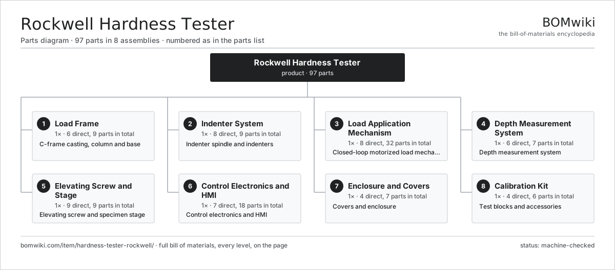
| # | Part | Qty | What it does |
|---|---|---|---|
| 1 | Load Frame 6 parts | 1× | C-frame casting, column and base |
| 2 | Indenter System 8 parts | 1× | Indenter spindle and indenters |
| 3 | Load Application Mechanism 8 parts | 1× | Closed-loop motorized load mechanism |
| 4 | Depth Measurement System 6 parts | 1× | Depth measurement system |
| 5 | Elevating Screw and Stage 9 parts | 1× | Elevating screw and specimen stage |
| 6 | Control Electronics and HMI 7 parts | 1× | Control electronics and HMI |
| 7 | Enclosure and Covers 4 parts | 1× | Covers and enclosure |
| 8 | Calibration Kit 4 parts | 1× | Test blocks and accessories |
3D model
No 3D model yet. Have a CAD file of this? Add a 3D model — STL renders right on this page; STEP, FreeCAD, and OpenSCAD sources are welcome too (openly licensed, like all 3D models on BOMwiki).
Build & assembly graph
expand / collapse · shared sub-assemblies converge · links to related products · est. labourTap an assembly to expand/collapse · tap a part to open it · use “Open page” for any node · drag to pan, scroll to zoom.
Bill of materials for Rockwell Hardness Tester
8 top-level lines · 71 rows shown · 97 parts total · indented to 3 levels| # | Item / sub-assembly | Part no. | Qty/assy | Ext. qty | Parts | Type |
|---|---|---|---|---|---|---|
| 1 | Load Frame 6 parts | hardness-tester-rockwell-load-frame | 1× | 1 | 9 | assembly |
| 1.1 | C-Frame Casting | hardness-tester-rockwell-c-frame | 1× | 1 | · | part |
| 1.2 | Base Plate | hardness-tester-rockwell-base-plate | 1× | 1 | · | part |
| 1.3 | Spindle Housing | hardness-tester-rockwell-spindle-housing | 1× | 1 | · | part |
| 1.4 | Leveling Foot | hardness-tester-rockwell-leveling-foot | 3× | 3 | · | part |
| 1.5 | Frame Tie Rod | hardness-tester-rockwell-frame-tie | 2× | 2 | · | part |
| 1.6 | Fastener Set | fastener-set | 1× | 1 | · | part |
| 2 | Indenter System 8 parts | hardness-tester-rockwell-indenter-system | 1× | 1 | 9 | assembly |
| 2.1 | Indenter Spindle | hardness-tester-rockwell-indenter-spindle | 1× | 1 | · | part |
| 2.2 | Indenter Holder | hardness-tester-rockwell-indenter-holder | 1× | 1 | · | part |
| 2.3 | Diamond Brale Indenter | hardness-tester-rockwell-diamond-indenter | 1× | 1 | · | part |
| 2.4 | Ball Indenter 1/16 in | hardness-tester-rockwell-ball-indenter-116 | 1× | 1 | · | part |
| 2.5 | Ball Indenter 1/8 in | hardness-tester-rockwell-ball-indenter-18 | 1× | 1 | · | part |
| 2.6 | Spindle Guide Bearing | hardness-tester-rockwell-spindle-bearing | 2× | 2 | · | part |
| 2.7 | Spindle Return Spring | hardness-tester-rockwell-spindle-return-spring | 1× | 1 | · | part |
| 2.8 | O-Ring Set | oring-set | 1× | 1 | · | part |
| 3 | Load Application Mechanism 8 parts | hardness-tester-rockwell-load-mechanism | 1× | 1 | 32 | assembly |
| 3.1 | Servo Motor 4 parts | servo-motor | 1× | 1 | 24 | assembly |
| 3.1.1 | Stator Assembly 3 parts + deeper › | stator-assembly | 1× | 1 | 3 | assembly |
| 3.1.2 | Rotor Assembly 4 parts + deeper › | rotor-assembly | 1× | 1 | 19 | assembly |
| 3.1.3 | Encoder | encoder | 1× | 1 | · | part |
| 3.1.4 | Motor Housing | motor-housing | 1× | 1 | · | part |
| 3.2 | Ball Screw | ball-screw | 1× | 1 | · | part |
| 3.3 | Load Cell | hardness-tester-rockwell-load-cell | 1× | 1 | · | part |
| 3.4 | Load Yoke | hardness-tester-rockwell-load-yoke | 1× | 1 | · | part |
| 3.5 | Servo Coupling | hardness-tester-rockwell-load-coupling | 1× | 1 | · | part |
| 3.6 | Ball Bearing | ball-bearing | 2× | 2 | · | part |
| 3.7 | Overload Stop | hardness-tester-rockwell-overload-stop | 1× | 1 | · | part |
| 3.8 | Deadweight Set | hardness-tester-rockwell-weight-set | 1× | 1 | · | part |
| 4 | Depth Measurement System 6 parts | hardness-tester-rockwell-depth-system | 1× | 1 | 7 | assembly |
| 4.1 | Linear Encoder | hardness-tester-rockwell-linear-encoder | 1× | 1 | · | part |
| 4.2 | LVDT Sensor | hardness-tester-rockwell-lvdt | 1× | 1 | · | part |
| 4.3 | Encoder Glass Scale | hardness-tester-rockwell-encoder-scale | 1× | 1 | · | part |
| 4.4 | Sensor Bracket | hardness-tester-rockwell-sensor-bracket | 1× | 1 | · | part |
| 4.5 | Reference Bar | hardness-tester-rockwell-reference-bar | 1× | 1 | · | part |
| 4.6 | Connector | connector | 2× | 2 | · | part |
| 5 | Elevating Screw and Stage 9 parts | hardness-tester-rockwell-elevating-system | 1× | 1 | 9 | assembly |
| 5.1 | Elevating Screw | hardness-tester-rockwell-elevating-screw | 1× | 1 | · | part |
| 5.2 | Elevating Handwheel | hardness-tester-rockwell-handwheel | 1× | 1 | · | part |
| 5.3 | Stage Table | hardness-tester-rockwell-stage-table | 1× | 1 | · | part |
| 5.4 | Flat Anvil | hardness-tester-rockwell-anvil-flat | 1× | 1 | · | part |
| 5.5 | V Anvil | hardness-tester-rockwell-anvil-v | 1× | 1 | · | part |
| 5.6 | Spot Anvil | hardness-tester-rockwell-anvil-spot | 1× | 1 | · | part |
| 5.7 | Specimen Clamp | hardness-tester-rockwell-specimen-clamp | 1× | 1 | · | part |
| 5.8 | Screw Bellows | hardness-tester-rockwell-screw-bellows | 1× | 1 | · | part |
| 5.9 | Ball Bearing | ball-bearing | 1× | 1 | · | part |
| 6 | Control Electronics and HMI 7 parts | hardness-tester-rockwell-control-system | 1× | 1 | 18 | assembly |
| 6.1 | Main Controller Board 4 parts | hardness-tester-rockwell-main-board | 1× | 1 | 6 | assembly |
| 6.1.1 | Bare PCB | pcb-bare | 1× | 1 | · | part |
| 6.1.2 | Microcontroller | mcu | 1× | 1 | · | part |
| 6.1.3 | SMD Passive (R/C/L) | smd-passives | 1× | 1 | · | part |
| 6.1.4 | Connector | connector | 3× | 3 | · | part |
| 6.2 | Load Cell Amplifier Board 3 parts | hardness-tester-rockwell-loadcell-amp | 1× | 1 | 4 | assembly |
| 6.2.1 | Bare PCB | pcb-bare | 1× | 1 | · | part |
| 6.2.2 | SMD Passive (R/C/L) | smd-passives | 1× | 1 | · | part |
| 6.2.3 | Connector | connector | 2× | 2 | · | part |
| 6.3 | LCD Panel | lcd-panel | 1× | 1 | · | part |
| 6.4 | Power Supply | power-supply | 1× | 1 | · | part |
| 6.5 | Servo Driver | hardness-tester-rockwell-servo-driver | 1× | 1 | · | part |
| 6.6 | Wire Bundle | wire-bundle | 1× | 1 | · | part |
| 6.7 | Connector | connector | 4× | 4 | · | part |
| 7 | Enclosure and Covers 4 parts | hardness-tester-rockwell-enclosure | 1× | 1 | 7 | assembly |
| 7.1 | Sheet Metal Panel | sheet-panel | 4× | 4 | · | part |
| 7.2 | Front Panel | hardness-tester-rockwell-front-panel | 1× | 1 | · | part |
| 7.3 | Dust Shield | hardness-tester-rockwell-dust-shield | 1× | 1 | · | part |
| 7.4 | Fastener Set | fastener-set | 1× | 1 | · | part |
| 8 | Calibration Kit 4 parts | hardness-tester-rockwell-calibration-kit | 1× | 1 | 6 | assembly |
| 8.1 | HRC Test Block | hardness-tester-rockwell-test-block-hrc | 2× | 2 | · | part |
| 8.2 | HRB Test Block | hardness-tester-rockwell-test-block-hrb | 2× | 2 | · | part |
| 8.3 | Indenter Case | hardness-tester-rockwell-indenter-case | 1× | 1 | · | part |
| 8.4 | Anvil Wrench | hardness-tester-rockwell-anvil-wrench | 1× | 1 | · | part |
Related products
same domain, ranked by shared parts Flow Cytometer
110 parts · shares 17 with this page
Total Station
86 parts · shares 12 with this page
Automatic Titrator
65 parts · shares 16 with this page
Flow Cytometer
110 parts · shares 17 with this page
Total Station
86 parts · shares 12 with this page
Automatic Titrator
65 parts · shares 16 with this page
 Scanning Electron Microscope
1,000 parts · shares 16 with this page
Scanning Electron Microscope
1,000 parts · shares 16 with this page
 Atomic Absorption Spectrometer
648 parts · shares 15 with this page
Dissolution Tester
370 parts · shares 15 with this page
Atomic Absorption Spectrometer
648 parts · shares 15 with this page
Dissolution Tester
370 parts · shares 15 with this page
Sourcing: possible vendors
Prices, MOQ, and lead times are algorithmic estimates, not quotes, and not claims about these companies. Company mappings are curated by keyword; est. price band $1k–$500k. How estimates work| Vendor | HQ | Specialty | MOQ | Lead time |
|---|---|---|---|---|
| thermofisher.com ↗ | Waltham, US | Lab instruments | 100 units | 10–18 wks |
|
🇺🇸Agilent
agilent.com ↗
|
Santa Clara, US | Analytical instruments | 100 units | 10–18 wks |
|
🇺🇸Bruker
bruker.com ↗
|
Billerica, US | Scientific instruments | 100 units | 10–18 wks |
|
🇯🇵Shimadzu
shimadzu.com ↗
|
Kyoto, JP | Analytical instruments | 100 units | 10–18 wks |
|
🇺🇸Waters
waters.com ↗
|
Milford, US | Chromatography & MS | 100 units | 10–18 wks |
993-word article