Hydraulic Pile Hammer
ProductOverview
A hydraulic pile hammer drives piles into the ground by repeatedly lifting a heavy steel ram and dropping it onto the pile head. Unlike a diesel hammer, which burns fuel in the cylinder to throw the ram, this machine uses hydraulic oil from a power pack to raise the ram and then lets it fall under gravity, sometimes with an added downward push. The result is a clean, smoke-free blow whose energy can be set precisely, which matters when a pile must reach a target set without overstressing its head. A typical mid-size unit carries a ram of 3-7 t, lifts it 0.2-1.2 m, and delivers 10-130 kJ at up to 60 blows per minute.
The core of the machine is the Ram Assembly, which runs inside the Cylinder and Housing. Oil is supplied and switched by the Valve Block, buffered by the Accumulator System, and the blow is passed into the pile through the Drive Cap and Cushion. The Leader Mount keeps the hammer aligned, the Energy Monitor records what each blow delivers, and the Pile Sleeve Set adapts the cap to the pile section being driven.
Ram and cylinder
The ram is a forged steel mass that does the work. On the lift stroke the Valve Block sends oil under the Piston Head, pushing the Drive Piston Rod up and raising the Ram against gravity. At the top of stroke the Drop Catch Valve vents the lift line, and the ram falls freely down the bore guided by the Ram Guide Liner set until it strikes the Anvil Block. Stroke height is adjustable, so the same hammer can deliver a soft 10 kJ tap to start a pile straight and a full 130 kJ blow once the pile is biting.
All of this runs inside the Cylinder Tube, a honed bore rated for 320 bar working pressure, closed by the Cylinder End Cap pair and sealed at the rod by the Rod Gland. The cylinder and ram sit within the Housing Shell, a welded S355 structure that carries every load between the striking face and the leader. The Top Cover gives access to the catch valve and seals for service.
Hydraulic supply
Lifting a multi-tonne ram many times a minute creates a sharp, repeated demand for oil flow. The Accumulator System handles that peak so the power pack does not have to. Its Piston Accumulator units store oil under nitrogen pressure between blows and release it during the lift, letting a smaller pump sustain the blow rate. The Gas Charge Valve sets the pre-charge, and a Pressure Sensor watches it.
Oil reaches the hammer through the Hose Set and Quick Coupler connections, then through the Main Spool Valve, which switches the cylinder between lift and release to set the blow rate. The Relief Valve caps the system near 350 bar, and the Check Valve units let oil refill the cylinder as the ram drops.
Drive cap and cushions
The blow does not reach the pile as raw steel on steel. The Drive Cap and Cushion sits between the anvil and the pile head. Its Drive Cap holds two cushions: the Hammer Cushion, a stack of alternating aluminium and micarta that softens the impact and tunes how long the force pulse lasts, and the Pile Cushion, a sacrificial pad used on concrete piles to keep the head from spalling. Steel piles run without the lower cushion. The Wear Plate takes the strike-face wear, and an optional Acoustic Shroud cuts radiated noise on jobs in built-up areas.
Guidance and monitoring
The hammer can hang free on a crane through the Suspension Link, or run on a leader using the Guide Jaw pair and Slide Pad set, which keep the blow aligned with the pile axis as the pile sinks. Coil Spring preload holds the guides against the rail.
Pile-driving records call for an energy figure on every blow. The Stroke Sensor measures ram lift height, a Pressure Sensor reads working pressure, and the Monitor Controller turns those into transferred energy, blow rate, and a running blow count. The operator reads the result on the Operator Display in the cab.
Variants and use
A single hammer body covers many pile types through the Pile Sleeve Set set: the Sheet-Pile Insert grips a sheet-pile interlock, the Pipe-Pile Sleeve centers a tubular pile, and the H-Pile Insert matches the flanges of an H-section bearing pile. The Auto-Lubrication System meters grease to the ram guides and anvil while the hammer runs, which is what lets the machine drive thousands of blows a shift without the guides picking up. Hydraulic hammers in this class are used for marine sheet-pile walls, bridge and building foundations, and any site where a measured, low-emission blow is needed close to existing structures.
Hydraulic Pile Hammer parts and their functions
9 top-level parts · 85 parts in total · full bill of materials below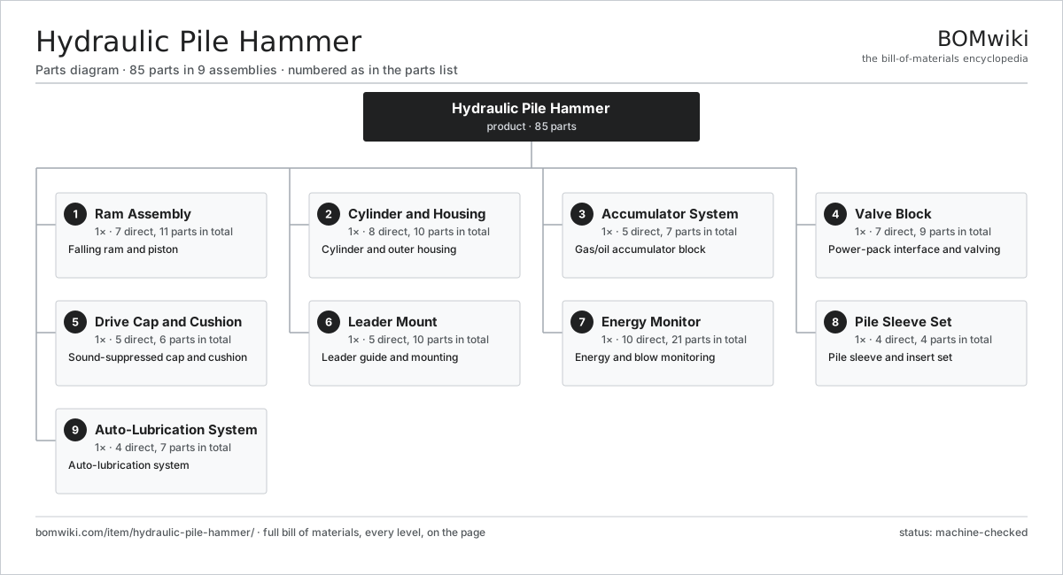
| # | Part | Qty | What it does |
|---|---|---|---|
| 1 | Ram Assembly 7 parts | 1× | Falling ram and piston |
| 2 | Cylinder and Housing 8 parts | 1× | Cylinder and outer housing |
| 3 | Accumulator System 5 parts | 1× | Gas/oil accumulator block |
| 4 | Valve Block 7 parts | 1× | Power-pack interface and valving |
| 5 | Drive Cap and Cushion 5 parts | 1× | Sound-suppressed cap and cushion |
| 6 | Leader Mount 5 parts | 1× | Leader guide and mounting |
| 7 | Energy Monitor 10 parts | 1× | Energy and blow monitoring |
| 8 | Pile Sleeve Set 4 parts | 1× | Pile sleeve and insert set |
| 9 | Auto-Lubrication System 4 parts | 1× | Auto-lubrication system |
3D model
No 3D model yet. Have a CAD file of this? Add a 3D model — STL renders right on this page; STEP, FreeCAD, and OpenSCAD sources are welcome too (openly licensed, like all 3D models on BOMwiki).
Build & assembly graph
expand / collapse · shared sub-assemblies converge · links to related products · est. labourTap an assembly to expand/collapse · tap a part to open it · use “Open page” for any node · drag to pan, scroll to zoom.
Bill of materials for Hydraulic Pile Hammer
9 top-level lines · 72 rows shown · 85 parts total · indented to 3 levels| # | Item / sub-assembly | Part no. | Qty/assy | Ext. qty | Parts | Type |
|---|---|---|---|---|---|---|
| 1 | Ram Assembly 7 parts | hydraulic-pile-hammer-ram-assembly | 1× | 1 | 11 | assembly |
| 1.1 | Ram | hydraulic-pile-hammer-ram | 1× | 1 | · | part |
| 1.2 | Drive Piston Rod | hydraulic-pile-hammer-piston-rod | 1× | 1 | · | part |
| 1.3 | Piston Head | hydraulic-pile-hammer-piston-head | 1× | 1 | · | part |
| 1.4 | Anvil Block | hydraulic-pile-hammer-anvil | 1× | 1 | · | part |
| 1.5 | Ram Guide Liner | hydraulic-pile-hammer-ram-liner | 4× | 4 | · | part |
| 1.6 | Drop Catch Valve | hydraulic-pile-hammer-catch | 1× | 1 | · | part |
| 1.7 | O-Ring Set | oring-set | 2× | 2 | · | part |
| 2 | Cylinder and Housing 8 parts | hydraulic-pile-hammer-cylinder-housing | 1× | 1 | 10 | assembly |
| 2.1 | Cylinder Tube | hydraulic-pile-hammer-cylinder-tube | 1× | 1 | · | part |
| 2.2 | Cylinder End Cap | hydraulic-pile-hammer-cylinder-cap | 2× | 2 | · | part |
| 2.3 | Housing Shell | hydraulic-pile-hammer-housing-shell | 1× | 1 | · | part |
| 2.4 | Top Cover | hydraulic-pile-hammer-housing-cover | 1× | 1 | · | part |
| 2.5 | Rod Gland | hydraulic-pile-hammer-rod-gland | 1× | 1 | · | part |
| 2.6 | Oil Seal | oil-seal | 2× | 2 | · | part |
| 2.7 | O-Ring Set | oring-set | 1× | 1 | · | part |
| 2.8 | Fastener Set | fastener-set | 1× | 1 | · | part |
| 3 | Accumulator System 5 parts | hydraulic-pile-hammer-accumulator-system | 1× | 1 | 7 | assembly |
| 3.1 | Piston Accumulator | hydraulic-pile-hammer-accumulator-bottle | 2× | 2 | · | part |
| 3.2 | Gas Charge Valve | hydraulic-pile-hammer-gas-valve | 2× | 2 | · | part |
| 3.3 | Accumulator Manifold | hydraulic-pile-hammer-acc-manifold | 1× | 1 | · | part |
| 3.4 | Pressure Sensor | pressure-sensor | 1× | 1 | · | part |
| 3.5 | O-Ring Set | oring-set | 1× | 1 | · | part |
| 4 | Valve Block 7 parts | hydraulic-pile-hammer-valve-block | 1× | 1 | 9 | assembly |
| 4.1 | Main Spool Valve | hydraulic-pile-hammer-main-spool | 1× | 1 | · | part |
| 4.2 | Relief Valve | hydraulic-pile-hammer-relief-valve | 1× | 1 | · | part |
| 4.3 | Check Valve | hydraulic-pile-hammer-check-valve | 2× | 2 | · | part |
| 4.4 | Hose Set | hydraulic-pile-hammer-hose-set | 1× | 1 | · | part |
| 4.5 | Quick Coupler | hydraulic-pile-hammer-quick-coupler | 2× | 2 | · | part |
| 4.6 | Pressure Sensor | pressure-sensor | 1× | 1 | · | part |
| 4.7 | O-Ring Set | oring-set | 1× | 1 | · | part |
| 5 | Drive Cap and Cushion 5 parts | hydraulic-pile-hammer-helmet | 1× | 1 | 6 | assembly |
| 5.1 | Drive Cap | hydraulic-pile-hammer-drive-cap | 1× | 1 | · | part |
| 5.2 | Hammer Cushion | hydraulic-pile-hammer-hammer-cushion | 1× | 1 | · | part |
| 5.3 | Pile Cushion | hydraulic-pile-hammer-pile-cushion | 1× | 1 | · | part |
| 5.4 | Acoustic Shroud | hydraulic-pile-hammer-sound-shroud | 1× | 1 | · | part |
| 5.5 | Wear Plate | hydraulic-pile-hammer-wear-plate | 2× | 2 | · | part |
| 6 | Leader Mount 5 parts | hydraulic-pile-hammer-leader-mount | 1× | 1 | 10 | assembly |
| 6.1 | Guide Jaw | hydraulic-pile-hammer-guide-jaw | 2× | 2 | · | part |
| 6.2 | Suspension Link | hydraulic-pile-hammer-suspension-link | 1× | 1 | · | part |
| 6.3 | Slide Pad | hydraulic-pile-hammer-slide-pad | 4× | 4 | · | part |
| 6.4 | Coil Spring | coil-spring | 2× | 2 | · | part |
| 6.5 | Fastener Set | fastener-set | 1× | 1 | · | part |
| 7 | Energy Monitor 10 parts | hydraulic-pile-hammer-monitor | 1× | 1 | 21 | assembly |
| 7.1 | Stroke Sensor | hydraulic-pile-hammer-stroke-sensor | 1× | 1 | · | part |
| 7.2 | Operator Display 3 parts | hydraulic-pile-hammer-display | 1× | 1 | 4 | assembly |
| 7.2.1 | LCD Panel | lcd-panel | 1× | 1 | · | part |
| 7.2.2 | Display Housing | hydraulic-pile-hammer-display-housing | 1× | 1 | · | part |
| 7.2.3 | Connector | connector | 2× | 2 | · | part |
| 7.3 | Monitor Controller 5 parts | hydraulic-pile-hammer-controller | 1× | 1 | 6 | assembly |
| 7.3.1 | Bare PCB | pcb-bare | 1× | 1 | · | part |
| 7.3.2 | Microcontroller | mcu | 1× | 1 | · | part |
| 7.3.3 | SMD Passive (R/C/L) | smd-passives | 1× | 1 | · | part |
| 7.3.4 | Relay | relay | 2× | 2 | · | part |
| 7.3.5 | Power Supply | power-supply | 1× | 1 | · | part |
| 7.4 | Pressure Sensor | pressure-sensor | 1× | 1 | · | part |
| 7.5 | LCD Panel | lcd-panel | 1× | 1 | · | part |
| 7.6 | Microcontroller | mcu | 1× | 1 | · | part |
| 7.7 | Bare PCB | pcb-bare | 1× | 1 | · | part |
| 7.8 | SMD Passive (R/C/L) | smd-passives | 1× | 1 | · | part |
| 7.9 | Wire Bundle | wire-bundle | 1× | 1 | · | part |
| 7.10 | Connector | connector | 4× | 4 | · | part |
| 8 | Pile Sleeve Set 4 parts | hydraulic-pile-hammer-sleeve | 1× | 1 | 4 | assembly |
| 8.1 | Sheet-Pile Insert | hydraulic-pile-hammer-sheet-insert | 1× | 1 | · | part |
| 8.2 | Pipe-Pile Sleeve | hydraulic-pile-hammer-pipe-insert | 1× | 1 | · | part |
| 8.3 | H-Pile Insert | hydraulic-pile-hammer-h-insert | 1× | 1 | · | part |
| 8.4 | Fastener Set | fastener-set | 1× | 1 | · | part |
| 9 | Auto-Lubrication System 4 parts | hydraulic-pile-hammer-lube-system | 1× | 1 | 7 | assembly |
| 9.1 | Grease Pump | hydraulic-pile-hammer-grease-pump | 1× | 1 | · | part |
| 9.2 | Grease Reservoir | hydraulic-pile-hammer-grease-reservoir | 1× | 1 | · | part |
| 9.3 | Metering Block | hydraulic-pile-hammer-metering-block | 1× | 1 | · | part |
| 9.4 | Lubrication Line | hydraulic-pile-hammer-lube-line | 4× | 4 | · | part |
Related products
same domain, ranked by shared parts Bridge Girder Launching Gantry
1,542 parts · shares 10 with this page
Dowel Bar Inserter
315 parts · shares 10 with this page
Bridge Girder Launching Gantry
1,542 parts · shares 10 with this page
Dowel Bar Inserter
315 parts · shares 10 with this page
 Drilling Rig Truck
310 parts · shares 10 with this page
Drilling Rig Truck
310 parts · shares 10 with this page
 Guardrail Installation Rig
320 parts · shares 10 with this page
Pile Driver
519 parts · shares 10 with this page
Guardrail Installation Rig
320 parts · shares 10 with this page
Pile Driver
519 parts · shares 10 with this page
 Pile Driver Hammer
258 parts · shares 10 with this page
Pile Driver Hammer
258 parts · shares 10 with this page
Sourcing: possible vendors
Prices, MOQ, and lead times are algorithmic estimates, not quotes, and not claims about these companies. Company mappings are curated by keyword; est. price band $15k–$2M. How estimates work| Vendor | HQ | Specialty | MOQ | Lead time |
|---|---|---|---|---|
| caterpillar.com ↗ | Irving, US | Construction & mining equipment | made to order | 16–28 wks |
|
🇯🇵Komatsu
komatsu.com ↗
|
Tokyo, JP | Construction & mining equipment | made to order | 16–28 wks |
|
🇸🇪Volvo CE
volvoce.com ↗
|
Gothenburg, SE | Construction equipment | made to order | 16–28 wks |
|
🇨🇭Liebherr
liebherr.com ↗
|
Bulle, CH | Cranes & heavy equipment | made to order | 16–28 wks |
|
🇨🇳XCMG
xcmg.com ↗
|
Xuzhou, CN | Construction machinery | made to order | 16–28 wks |
923-word article