Soil Mixing Rig
ProductOverview
A soil mixing rig stabilizes weak ground in place. Instead of digging soft soil out and replacing it, the rig drills augers into the ground and blends the natural soil with a cement or lime binder, so the soil itself becomes a stiff, low- permeability material. The result is a column or panel of soilcrete that carries load, cuts settlement, and blocks groundwater. Deep soil mixing is used under embankments, behind retaining walls, around excavations, and to lock up contaminated or liquefiable ground.
The machine is a tracked base carrier with a tall vertical mast. The rotary drive runs up and down that mast and turns the mixing tool, while a binder plant on or beside the rig batches the slurry and pumps it down the hollow shafts to the tool. The Base Carrier supplies power and stability, the Leader Mast guides and pushes the tool, the Rotary Drive Head spins it, the Mixing Tool does the blending, and the Binder Plant feeds it.
How a column is built
The operator positions the rig, plumbs the mast, and lowers the spinning mixing tool into the soil. As the augers cut downward, the Binder Plant pumps cement slurry through the Binder Swivel and down the Mixing Shaft bores to nozzles at the tool. The Auger Flight and Mixing Paddle shear the soil and slurry together. The tool is driven down to design depth, then withdrawn, often with a second pass to even out the mix. Binder is dosed against depth so each metre of column gets the cement quantity the mix design calls for, typically 150 to 400 kg of cement per cubic metre of treated soil.
Wet mixing pumps a cement slurry and suits most soils. Dry mixing blows powdered binder into the soil with compressed air and is used in soft, wet clays and peats where adding water would weaken the mix. The same carrier and drive serve both, with the binder plant configured for slurry or dry feed.
Mast and rotary drive
The Leader Mast is the backbone. Bolted Mast Section pieces set the working height, and machined Guide Rail faces let the drive head slide vertically without wandering. The Crowd Cylinder pair forces the tool down with enough crowd to advance the augers through stiff layers, while the Crowd Winch winch lifts the heavy drive head and the tool back out of the column.
The Rotary Drive Head carries the Drive Gearbox, where several Hydraulic Drive Motor hydraulic motors combine their output. Mixing needs high torque at low speed, often 100 to 300 kNm at 15 to 40 rpm, because the augers must turn through dense or cohesive ground while the paddles knead binder into it. Each Output Shaft runs on heavy Ball Bearing sets and is sealed with Oil Seal glands against the abrasive slurry that climbs the shafts.
The mixing tool
The Mixing Tool is purpose-built for the soil and column size. Single-shaft tools make round columns; triple-shaft tools cut overlapping panels for cutoff walls. Near the tip, Auger Flight sections and carbide Cutting Tooth points break up the ground. Above them, rows of Mixing Paddle blades blend soil and binder. Slurry exits through Injection Nozzle ports placed so binder enters where the paddles are working. Paddles and flights wear fast in abrasive ground and are built from wear plate and Hardox so worn sections can be replaced without scrapping the whole tool.
Binder plant and pumping
The Binder Plant meters and delivers the binder. Cement is stored in the Cement Silo and dropped into the Batch Mixer, a high-shear colloidal mixer that wets every grain at the chosen water-cement ratio. The Grout Pump, a progressive-cavity pump with a Pump Rotor turning in a Pump Stator, pushes slurry down the Binder Hose against ground pressure. A Flow Meter and Pressure Sensor track how much binder goes in and at what pressure, both of which feed the dosing logic.
Power, hydraulics and control
The Diesel Engine drives the Main Pump units in the Hydraulic System package, which supplies the high flow the drive motors need plus travel, slew, mast and crowd functions through the Valve Block. Sustained mixing makes heat, so the Oil Cooler holds oil temperature through a full shift.
Quality on a soil mixing job is proven by records, not by exposing the work, so the Electrical and Monitoring system logs everything. The Depth Encoder tracks tool depth, the Torque Sensor reads mixing energy as a proxy for soil strength, and the Rig Controller holds rotation, crowd rate and binder dose to the mix design. The Process Recorder saves a profile of every column so the engineer can confirm each one met the specification.
Variants and use
Rigs scale from compact 50 t machines for shallow lime stabilization to 120 t machines mixing 2.4 m columns to 40 m depth. The same family supports cutoff walls, load-bearing column grids under embankments and tanks, excavation support, and solidification of contaminated soils. Because the soil stays where it is and only binder is added, deep soil mixing moves far less spoil than dig-and-replace and is quieter and lower-vibration than driven piling, which makes it common on soft urban and waterfront sites.
Soil Mixing Rig parts and their functions
8 top-level parts · 226 parts in total · full bill of materials below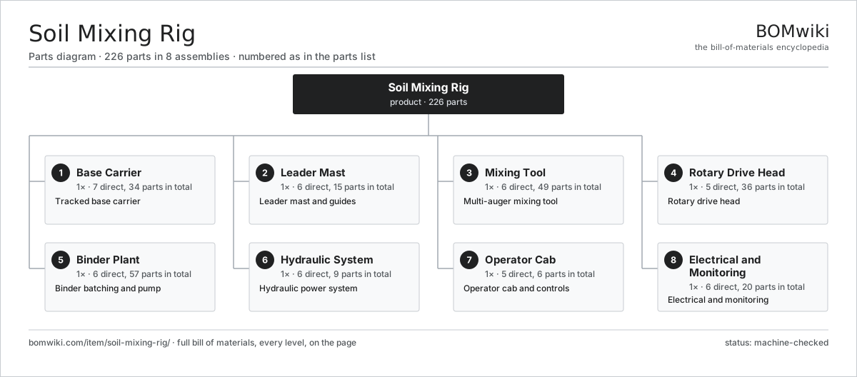
| # | Part | Qty | What it does |
|---|---|---|---|
| 1 | Base Carrier 7 parts | 1× | Tracked base carrier |
| 2 | Leader Mast 6 parts | 1× | Leader mast and guides |
| 3 | Mixing Tool 6 parts | 1× | Multi-auger mixing tool |
| 4 | Rotary Drive Head 5 parts | 1× | Rotary drive head |
| 5 | Binder Plant 6 parts | 1× | Binder batching and pump |
| 6 | Hydraulic System 6 parts | 1× | Hydraulic power system |
| 7 | Operator Cab 5 parts | 1× | Operator cab and controls |
| 8 | Electrical and Monitoring 6 parts | 1× | Electrical and monitoring |
3D model
No 3D model yet. Have a CAD file of this? Add a 3D model — STL renders right on this page; STEP, FreeCAD, and OpenSCAD sources are welcome too (openly licensed, like all 3D models on BOMwiki).
Build & assembly graph
expand / collapse · shared sub-assemblies converge · links to related products · est. labourTap an assembly to expand/collapse · tap a part to open it · use “Open page” for any node · drag to pan, scroll to zoom.
Bill of materials for Soil Mixing Rig
8 top-level lines · 85 rows shown · 226 parts total · indented to 3 levels| # | Item / sub-assembly | Part no. | Qty/assy | Ext. qty | Parts | Type |
|---|---|---|---|---|---|---|
| 1 | Base Carrier 7 parts | soil-mixing-rig-base-carrier | 1× | 1 | 34 | assembly |
| 1.1 | Track Frame | soil-mixing-rig-track-frame | 2× | 2 | · | part |
| 1.2 | Track Chain | soil-mixing-rig-track-chain | 2× | 2 | · | part |
| 1.3 | Track Travel Motor 4 parts | soil-mixing-rig-track-motor | 2× | 2 | 8 | assembly |
| 1.3.1 | Gearbox Housing | gearbox-housing | 1× | 2 | · | part |
| 1.3.2 | Helical Gear Pair | gear-pair | 2× | 4 | · | part |
| 1.3.3 | Ball Bearing | ball-bearing | 3× | 6 | · | part |
| 1.3.4 | Oil Seal | oil-seal | 2× | 4 | · | part |
| 1.4 | Slew Turntable 3 parts | soil-mixing-rig-turntable | 1× | 1 | 4 | assembly |
| 1.4.1 | Slew Ring | soil-mixing-rig-slew-ring | 1× | 1 | · | part |
| 1.4.2 | Helical Gear Pair | gear-pair | 1× | 1 | · | part |
| 1.4.3 | Ball Bearing | ball-bearing | 2× | 2 | · | part |
| 1.5 | Counterweight | soil-mixing-rig-counterweight | 1× | 1 | · | part |
| 1.6 | Diesel Engine 5 parts | soil-mixing-rig-diesel-engine | 1× | 1 | 8 | assembly |
| 1.6.1 | Engine Block | soil-mixing-rig-engine-block | 1× | 1 | · | part |
| 1.6.2 | Turbocharger | soil-mixing-rig-turbocharger | 1× | 1 | · | part |
| 1.6.3 | Cooling Package | soil-mixing-rig-radiator | 1× | 1 | · | part |
| 1.6.4 | Fuel Tank | soil-mixing-rig-fuel-tank | 1× | 1 | · | part |
| 1.6.5 | Oil Seal | oil-seal | 4× | 4 | · | part |
| 1.7 | Fastener Set | fastener-set | 1× | 1 | · | part |
| 2 | Leader Mast 6 parts | soil-mixing-rig-mast | 1× | 1 | 15 | assembly |
| 2.1 | Mast Section | soil-mixing-rig-mast-section | 3× | 3 | · | part |
| 2.2 | Guide Rail | soil-mixing-rig-guide-rail | 2× | 2 | · | part |
| 2.3 | Crowd Cylinder | soil-mixing-rig-crowd-cylinder | 2× | 2 | · | part |
| 2.4 | Crowd Winch 4 parts | soil-mixing-rig-crowd-rope | 1× | 1 | 5 | assembly |
| 2.4.1 | Winch Drum | soil-mixing-rig-winch-drum | 1× | 1 | · | part |
| 2.4.2 | Wire Rope | soil-mixing-rig-wire-rope | 1× | 1 | · | part |
| 2.4.3 | Gearbox Housing | gearbox-housing | 1× | 1 | · | part |
| 2.4.4 | Ball Bearing | ball-bearing | 2× | 2 | · | part |
| 2.5 | Mast Cylinder | soil-mixing-rig-mast-cylinder | 2× | 2 | · | part |
| 2.6 | Fastener Set | fastener-set | 1× | 1 | · | part |
| 3 | Mixing Tool 6 parts | soil-mixing-rig-mixing-tool | 1× | 1 | 49 | assembly |
| 3.1 | Mixing Shaft | soil-mixing-rig-mixing-shaft | 3× | 3 | · | part |
| 3.2 | Auger Flight | soil-mixing-rig-auger-flight | 3× | 3 | · | part |
| 3.3 | Mixing Paddle | soil-mixing-rig-mixing-paddle | 12× | 12 | · | part |
| 3.4 | Cutting Tooth | soil-mixing-rig-cutting-tooth | 24× | 24 | · | part |
| 3.5 | Injection Nozzle | soil-mixing-rig-injection-nozzle | 6× | 6 | · | part |
| 3.6 | Binder Swivel | soil-mixing-rig-swivel | 1× | 1 | · | part |
| 4 | Rotary Drive Head 5 parts | soil-mixing-rig-rotary-drive | 1× | 1 | 36 | assembly |
| 4.1 | Drive Gearbox 4 parts | soil-mixing-rig-drive-gearbox | 1× | 1 | 14 | assembly |
| 4.1.1 | Gearbox Housing | gearbox-housing | 1× | 1 | · | part |
| 4.1.2 | Helical Gear Pair | gear-pair | 4× | 4 | · | part |
| 4.1.3 | Ball Bearing | ball-bearing | 6× | 6 | · | part |
| 4.1.4 | Oil Seal | oil-seal | 3× | 3 | · | part |
| 4.2 | Hydraulic Drive Motor | soil-mixing-rig-drive-motor | 4× | 4 | · | part |
| 4.3 | Output Shaft | soil-mixing-rig-output-shaft | 3× | 3 | · | part |
| 4.4 | Ball Bearing | ball-bearing | 9× | 9 | · | part |
| 4.5 | Oil Seal | oil-seal | 6× | 6 | · | part |
| 5 | Binder Plant 6 parts | soil-mixing-rig-binder-plant | 1× | 1 | 57 | assembly |
| 5.1 | Cement Silo | soil-mixing-rig-silo | 1× | 1 | · | part |
| 5.2 | Batch Mixer 3 parts | soil-mixing-rig-batch-mixer | 1× | 1 | 26 | assembly |
| 5.2.1 | Mixer Tank | soil-mixing-rig-mixer-tank | 1× | 1 | · | part |
| 5.2.2 | Servo Motor 4 parts + deeper › | servo-motor | 1× | 1 | 24 | assembly |
| 5.2.3 | Mixer Impeller | soil-mixing-rig-mixer-impeller | 1× | 1 | · | part |
| 5.3 | Grout Pump 3 parts | soil-mixing-rig-grout-pump | 1× | 1 | 26 | assembly |
| 5.3.1 | Pump Rotor | soil-mixing-rig-pump-rotor | 1× | 1 | · | part |
| 5.3.2 | Pump Stator | soil-mixing-rig-pump-stator | 1× | 1 | · | part |
| 5.3.3 | Servo Motor 4 parts + deeper › | servo-motor | 1× | 1 | 24 | assembly |
| 5.4 | Flow Meter | soil-mixing-rig-flow-meter | 1× | 1 | · | part |
| 5.5 | Binder Hose | soil-mixing-rig-binder-hose | 1× | 1 | · | part |
| 5.6 | Pressure Sensor | pressure-sensor | 2× | 2 | · | part |
| 6 | Hydraulic System 6 parts | soil-mixing-rig-hydraulics | 1× | 1 | 9 | assembly |
| 6.1 | Main Pump | soil-mixing-rig-main-pump | 2× | 2 | · | part |
| 6.2 | Valve Block | soil-mixing-rig-valve-block | 1× | 1 | · | part |
| 6.3 | Reservoir | soil-mixing-rig-reservoir | 1× | 1 | · | part |
| 6.4 | Oil Cooler | soil-mixing-rig-oil-cooler | 1× | 1 | · | part |
| 6.5 | O-Ring Set | oring-set | 1× | 1 | · | part |
| 6.6 | Pressure Sensor | pressure-sensor | 3× | 3 | · | part |
| 7 | Operator Cab 5 parts | soil-mixing-rig-cab | 1× | 1 | 6 | assembly |
| 7.1 | Cab Shell | soil-mixing-rig-cab-shell | 1× | 1 | · | part |
| 7.2 | Operator Seat | soil-mixing-rig-seat | 1× | 1 | · | part |
| 7.3 | Control Joystick | soil-mixing-rig-joystick | 2× | 2 | · | part |
| 7.4 | LCD Panel | lcd-panel | 1× | 1 | · | part |
| 7.5 | Cab HVAC | soil-mixing-rig-hvac | 1× | 1 | · | part |
| 8 | Electrical and Monitoring 6 parts | soil-mixing-rig-electrical | 1× | 1 | 20 | assembly |
| 8.1 | Rig Controller 4 parts | soil-mixing-rig-controller | 1× | 1 | 7 | assembly |
| 8.1.1 | Bare PCB | pcb-bare | 1× | 1 | · | part |
| 8.1.2 | Microcontroller | mcu | 1× | 1 | · | part |
| 8.1.3 | SMD Passive (R/C/L) | smd-passives | 1× | 1 | · | part |
| 8.1.4 | Relay | relay | 4× | 4 | · | part |
| 8.2 | Depth Encoder | soil-mixing-rig-depth-encoder | 1× | 1 | · | part |
| 8.3 | Torque Sensor | soil-mixing-rig-torque-sensor | 1× | 1 | · | part |
| 8.4 | Process Recorder | soil-mixing-rig-data-recorder | 1× | 1 | · | part |
| 8.5 | Wire Bundle | wire-bundle | 2× | 2 | · | part |
| 8.6 | Connector | connector | 8× | 8 | · | part |
Related products
same domain, ranked by shared parts Asphalt Recycler
226 parts · shares 21 with this page
Asphalt Recycler
226 parts · shares 21 with this page
 Bridge Girder Launching Gantry
1,542 parts · shares 21 with this page
Bridge Girder Launching Gantry
1,542 parts · shares 21 with this page
 Flat-Top Tower Crane
358 parts · shares 21 with this page
Flat-Top Tower Crane
358 parts · shares 21 with this page
 Ground Anchor Drill Rig
142 parts · shares 21 with this page
Ground Anchor Drill Rig
142 parts · shares 21 with this page
 Guardrail Installation Rig
320 parts · shares 21 with this page
Guardrail Installation Rig
320 parts · shares 21 with this page
 Jet Grouting Rig
154 parts · shares 21 with this page
Jet Grouting Rig
154 parts · shares 21 with this page
Sourcing: possible vendors
Prices, MOQ, and lead times are algorithmic estimates, not quotes, and not claims about these companies. Company mappings are curated by keyword; est. price band $15k–$2M. How estimates work| Vendor | HQ | Specialty | MOQ | Lead time |
|---|---|---|---|---|
| caterpillar.com ↗ | Irving, US | Construction & mining equipment | made to order | 16–28 wks |
|
🇯🇵Komatsu
komatsu.com ↗
|
Tokyo, JP | Construction & mining equipment | made to order | 16–28 wks |
|
🇸🇪Volvo CE
volvoce.com ↗
|
Gothenburg, SE | Construction equipment | made to order | 16–28 wks |
|
🇨🇭Liebherr
liebherr.com ↗
|
Bulle, CH | Cranes & heavy equipment | made to order | 16–28 wks |
|
🇨🇳XCMG
xcmg.com ↗
|
Xuzhou, CN | Construction machinery | made to order | 16–28 wks |
992-word article