Guardrail Installation Rig
ProductOverview
A guardrail installation rig is a self-contained truck that drives steel guardrail posts into the road shoulder and bolts the W-beam rail to them. It combines a percussion post driver, a positioning boom, a hydraulic bolting tool, and on-board material storage so that one machine and a small crew can build continuous guardrail along a highway without a separate excavator, drill rig, or crane. The rig works from the shoulder, parking on its outriggers to drive a run of posts, then moving forward to the next set.
The carrier provides both mobility and power. The diesel engine drives the wheels for road travel and runs a power take-off that turns the hydraulic pump, so the same engine powers driving, the boom, the bolter, and the outriggers. The Control System sequences the cycle and counts driving blows so the operator can confirm each post has reached refusal at the design depth.
Carrier Truck
The Carrier Truck Chassis is a heavy commercial 4x4 truck reinforced under the boom mount and outrigger pads. A turbocharged Diesel Engine of 4.5-7.0 L drives the Drive Axle pair and the Power Take-Off that powers the hydraulics. The PTO runs off the gearbox so the pump can turn while the truck is parked. The Ladder Chassis Frame carries the working loads from the driver and boom into the suspension and outriggers, and the engine uses a common-rail Fuel Injector set and a Turbocharger for the mid-range torque that hammer and travel duty demand.
Post Driver
The Hydraulic Post Driver is the heart of the rig. A Percussion Hammer Mass mass of 200-500 kg delivers 2-6 kJ per blow at 40-90 blows per minute, driving steel or timber posts 1.1-1.8 m into the shoulder. The Driver Guide Mast guides the hammer and post in a straight line, riding on Linear Guide Rail slides, and a Post Drive Cap protects the post head and keeps the blow square. The Hammer Cylinder lifts and accelerates the hammer each stroke, working at 350 bar with a Piston Rod sized against the load reversal at impact. A Pressure Sensor reads the percussion line so the controller can count blows and detect refusal when a post hits rock or hardpan.
Positioning Boom
The Positioning Boom places the driver over each post position and along the shoulder line. It is a knuckle boom built from Boom Section arms on a Slew Bearing that allows full rotation, driven by a Slew Drive Motor. Three Boom Cylinder units handle lift, extension, and driver tilt so the mast can be set plumb on a crossfall or angled to match a curve. The boom reaches 4-7 m, which covers the offset from the parked truck to the post line on most highway sections without repositioning for every post.
Bolting Unit
Once a run of posts is driven, the Beam Bolting Unit fastens the W-beam to them. A Beam Holding Clamp holds the rail aligned with the post slots while a Hydraulic Torque Wrench runs up the M16 post bolts to 200-300 Nm. The wrench is a reaction torque tool driven by a Hydraulic Motor through a Helical Gear Pair, and a Pressure Sensor reports the achieved torque so the crew can verify each connection. The Clamp Cylinder closes the clamp and reacts the torque load so the rail does not move during tightening.
Hydraulic System
All functions draw from the Hydraulic Power System. A tandem Hydraulic Pump supplies 350 bar to the percussion circuit and 250 bar to the boom, outriggers, and bolter. A load-sensing Directional Valve Bank of proportional Proportional Spool Valve sections gives the operator fine control of the boom while the driver runs at full flow. Percussion work generates heat, so an Oil Cooler with a servo-driven fan keeps the return oil within limits. A Pressure Relief Valve protects the percussion circuit, and the pump shaft runs on Ball Bearing supports behind an Oil Seal.
Material Storage and Stabilizers
The Material Storage Rack carries the day's stock: a Post Cradle holding 30-60 posts, a Beam Cradle of 4 m W-beam sections, and Fastener Bin containers for fasteners, all within reach of the boom. Before driving, the operator deploys the Stabilizer Outrigger legs. Each one extends a Outrigger Slide Beam on a Linear Guide Rail and lowers an Outrigger Pad to spread the load on the shoulder, leveling the truck so the mast can be set plumb and the boom moment is reacted into the ground rather than the suspension.
Control and Field Use
The Control System gives the crew a cab console and a belly-pack Operator Remote so the operator can run the boom and driver from the work zone where they can see the post. The PLC Module counts blows, enforces outrigger interlocks so the boom cannot swing before the rig is stable, and logs the driving record for each post. In a typical shift a two or three person crew installs 40-80 posts plus rail, working in a rolling closure with the rig leading and a follow-up crew checking torque and rail splices. Working from the shoulder under live or coned traffic, the rig keeps the crew out of the lane and away from the percussion zone during driving.
Guardrail Installation Rig parts and their functions
8 top-level parts · 320 parts in total · full bill of materials below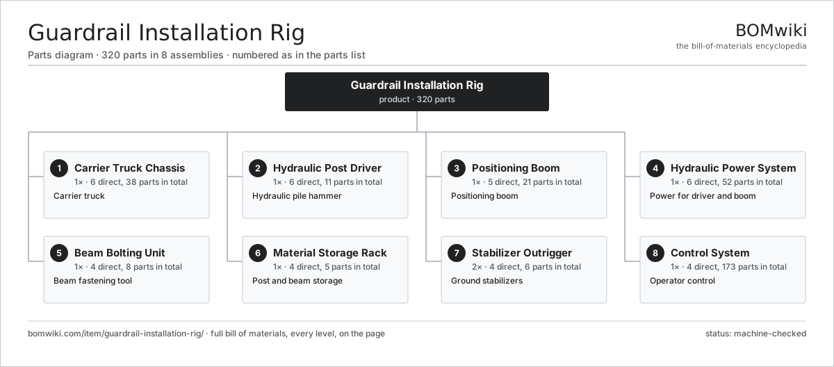
| # | Part | Qty | What it does |
|---|---|---|---|
| 1 | Carrier Truck Chassis 6 parts | 1× | Carrier truck |
| 2 | Hydraulic Post Driver 6 parts | 1× | Hydraulic pile hammer |
| 3 | Positioning Boom 5 parts | 1× | Positioning boom |
| 4 | Hydraulic Power System 6 parts | 1× | Power for driver and boom |
| 5 | Beam Bolting Unit 4 parts | 1× | Beam fastening tool |
| 6 | Material Storage Rack 4 parts | 1× | Post and beam storage |
| 7 | Stabilizer Outrigger 4 parts | 2× | Ground stabilizers |
| 8 | Control System 4 parts | 1× | Operator control |
3D model
No 3D model yet. Have a CAD file of this? Add a 3D model — STL renders right on this page; STEP, FreeCAD, and OpenSCAD sources are welcome too (openly licensed, like all 3D models on BOMwiki).
Build & assembly graph
expand / collapse · shared sub-assemblies converge · links to related products · est. labourTap an assembly to expand/collapse · tap a part to open it · use “Open page” for any node · drag to pan, scroll to zoom.
Bill of materials for Guardrail Installation Rig
8 top-level lines · 96 rows shown · 320 parts total · indented to 3 levels| # | Item / sub-assembly | Part no. | Qty/assy | Ext. qty | Parts | Type |
|---|---|---|---|---|---|---|
| 1 | Carrier Truck Chassis 6 parts | guardrail-installation-rig-truck-chassis | 1× | 1 | 38 | assembly |
| 1.1 | Diesel Engine 4 parts | guardrail-installation-rig-diesel-engine | 1× | 1 | 12 | assembly |
| 1.1.1 | Engine Block | guardrail-installation-rig-engine-block | 1× | 1 | · | part |
| 1.1.2 | Turbocharger | guardrail-installation-rig-turbocharger | 1× | 1 | · | part |
| 1.1.3 | Fuel Injector | guardrail-installation-rig-fuel-injector | 6× | 6 | · | part |
| 1.1.4 | Ball Bearing | ball-bearing | 4× | 4 | · | part |
| 1.2 | Power Take-Off 4 parts | guardrail-installation-rig-pto | 1× | 1 | 6 | assembly |
| 1.2.1 | Helical Gear Pair | gear-pair | 1× | 1 | · | part |
| 1.2.2 | Gearbox Housing | gearbox-housing | 1× | 1 | · | part |
| 1.2.3 | Ball Bearing | ball-bearing | 2× | 2 | · | part |
| 1.2.4 | Oil Seal | oil-seal | 2× | 2 | · | part |
| 1.3 | Ladder Chassis Frame | guardrail-installation-rig-chassis-frame | 1× | 1 | · | part |
| 1.4 | Drive Axle 3 parts | guardrail-installation-rig-axle | 2× | 2 | 7 | assembly |
| 1.4.1 | Helical Gear Pair | gear-pair | 1× | 2 | · | part |
| 1.4.2 | Ball Bearing | ball-bearing | 4× | 8 | · | part |
| 1.4.3 | Oil Seal | oil-seal | 2× | 4 | · | part |
| 1.5 | Coil Spring | coil-spring | 4× | 4 | · | part |
| 1.6 | Fastener Set | fastener-set | 1× | 1 | · | part |
| 2 | Hydraulic Post Driver 6 parts | guardrail-installation-rig-post-driver | 1× | 1 | 11 | assembly |
| 2.1 | Percussion Hammer Mass | guardrail-installation-rig-hammer | 1× | 1 | · | part |
| 2.2 | Driver Guide Mast | guardrail-installation-rig-mast | 1× | 1 | · | part |
| 2.3 | Post Drive Cap | guardrail-installation-rig-drive-cap | 1× | 1 | · | part |
| 2.4 | Hammer Cylinder 4 parts | guardrail-installation-rig-hammer-cylinder | 1× | 1 | 5 | assembly |
| 2.4.1 | Cylinder Tube | guardrail-installation-rig-cylinder-tube | 1× | 1 | · | part |
| 2.4.2 | Piston Rod | guardrail-installation-rig-piston-rod | 1× | 1 | · | part |
| 2.4.3 | O-Ring Set | oring-set | 1× | 1 | · | part |
| 2.4.4 | Oil Seal | oil-seal | 2× | 2 | · | part |
| 2.5 | Linear Guide Rail | linear-guide | 2× | 2 | · | part |
| 2.6 | Pressure Sensor | pressure-sensor | 1× | 1 | · | part |
| 3 | Positioning Boom 5 parts | guardrail-installation-rig-boom | 1× | 1 | 21 | assembly |
| 3.1 | Boom Section | guardrail-installation-rig-boom-section | 2× | 2 | · | part |
| 3.2 | Slew Bearing | guardrail-installation-rig-slew-bearing | 1× | 1 | · | part |
| 3.3 | Boom Cylinder 3 parts | guardrail-installation-rig-boom-cylinder | 3× | 3 | 3 | assembly |
| 3.3.1 | Cylinder Tube | guardrail-installation-rig-cylinder-tube | 1× | 3 | · | part |
| 3.3.2 | Piston Rod | guardrail-installation-rig-piston-rod | 1× | 3 | · | part |
| 3.3.3 | O-Ring Set | oring-set | 1× | 3 | · | part |
| 3.4 | Slew Drive Motor 4 parts | guardrail-installation-rig-slew-motor | 1× | 1 | 5 | assembly |
| 3.4.1 | Helical Gear Pair | gear-pair | 1× | 1 | · | part |
| 3.4.2 | Gearbox Housing | gearbox-housing | 1× | 1 | · | part |
| 3.4.3 | Ball Bearing | ball-bearing | 2× | 2 | · | part |
| 3.4.4 | Oil Seal | oil-seal | 1× | 1 | · | part |
| 3.5 | Ball Bearing | ball-bearing | 4× | 4 | · | part |
| 4 | Hydraulic Power System 6 parts | guardrail-installation-rig-hydraulic-system | 1× | 1 | 52 | assembly |
| 4.1 | Hydraulic Pump 4 parts | guardrail-installation-rig-hydraulic-pump | 1× | 1 | 5 | assembly |
| 4.1.1 | Pump Housing | guardrail-installation-rig-pump-housing | 1× | 1 | · | part |
| 4.1.2 | Helical Gear Pair | gear-pair | 1× | 1 | · | part |
| 4.1.3 | Ball Bearing | ball-bearing | 2× | 2 | · | part |
| 4.1.4 | Oil Seal | oil-seal | 1× | 1 | · | part |
| 4.2 | Directional Valve Bank 3 parts | guardrail-installation-rig-valve-bank | 1× | 1 | 18 | assembly |
| 4.2.1 | Proportional Spool Valve | guardrail-installation-rig-spool-valve | 8× | 8 | · | part |
| 4.2.2 | Pressure Relief Valve | guardrail-installation-rig-relief-valve | 2× | 2 | · | part |
| 4.2.3 | Relay | relay | 8× | 8 | · | part |
| 4.3 | Hydraulic Reservoir | guardrail-installation-rig-reservoir | 1× | 1 | · | part |
| 4.4 | Oil Cooler 2 parts | guardrail-installation-rig-oil-cooler | 1× | 1 | 25 | assembly |
| 4.4.1 | Cooler Core | guardrail-installation-rig-cooler-core | 1× | 1 | · | part |
| 4.4.2 | Servo Motor 4 parts + deeper › | servo-motor | 1× | 1 | 24 | assembly |
| 4.5 | Hose and Fitting Set | guardrail-installation-rig-hose-set | 1× | 1 | · | part |
| 4.6 | O-Ring Set | oring-set | 2× | 2 | · | part |
| 5 | Beam Bolting Unit 4 parts | guardrail-installation-rig-bolting-unit | 1× | 1 | 8 | assembly |
| 5.1 | Hydraulic Torque Wrench 3 parts | guardrail-installation-rig-torque-wrench | 1× | 1 | 4 | assembly |
| 5.1.1 | Hydraulic Motor | guardrail-installation-rig-hyd-motor | 1× | 1 | · | part |
| 5.1.2 | Helical Gear Pair | gear-pair | 1× | 1 | · | part |
| 5.1.3 | Ball Bearing | ball-bearing | 2× | 2 | · | part |
| 5.2 | Beam Holding Clamp | guardrail-installation-rig-beam-clamp | 1× | 1 | · | part |
| 5.3 | Clamp Cylinder 2 parts | guardrail-installation-rig-clamp-cylinder | 1× | 1 | 2 | assembly |
| 5.3.1 | Cylinder Tube | guardrail-installation-rig-cylinder-tube | 1× | 1 | · | part |
| 5.3.2 | O-Ring Set | oring-set | 1× | 1 | · | part |
| 5.4 | Pressure Sensor | pressure-sensor | 1× | 1 | · | part |
| 6 | Material Storage Rack 4 parts | guardrail-installation-rig-material-rack | 1× | 1 | 5 | assembly |
| 6.1 | Post Cradle | guardrail-installation-rig-post-rack | 1× | 1 | · | part |
| 6.2 | Beam Cradle | guardrail-installation-rig-beam-rack | 1× | 1 | · | part |
| 6.3 | Fastener Bin | guardrail-installation-rig-bolt-bin | 2× | 2 | · | part |
| 6.4 | Fastener Set | fastener-set | 1× | 1 | · | part |
| 7 | Stabilizer Outrigger 4 parts | guardrail-installation-rig-outrigger | 2× | 2 | 6 | assembly |
| 7.1 | Outrigger Cylinder 3 parts | guardrail-installation-rig-outrigger-cylinder | 1× | 2 | 3 | assembly |
| 7.1.1 | Cylinder Tube | guardrail-installation-rig-cylinder-tube | 1× | 2 | · | part |
| 7.1.2 | Piston Rod | guardrail-installation-rig-piston-rod | 1× | 2 | · | part |
| 7.1.3 | O-Ring Set | oring-set | 1× | 2 | · | part |
| 7.2 | Outrigger Pad | guardrail-installation-rig-outrigger-pad | 1× | 2 | · | part |
| 7.3 | Outrigger Slide Beam | guardrail-installation-rig-outrigger-beam | 1× | 2 | · | part |
| 7.4 | Linear Guide Rail | linear-guide | 1× | 2 | · | part |
| 8 | Control System 4 parts | guardrail-installation-rig-control-system | 1× | 1 | 173 | assembly |
| 8.1 | PLC Module 4 parts | guardrail-installation-rig-plc | 1× | 1 | 142 | assembly |
| 8.1.1 | Bare PCB | pcb-bare | 1× | 1 | · | part |
| 8.1.2 | Microcontroller | mcu | 1× | 1 | · | part |
| 8.1.3 | SMD Passive (R/C/L) | smd-passives | 130× | 130 | · | part |
| 8.1.4 | Connector | connector | 10× | 10 | · | part |
| 8.2 | Operator Remote 4 parts | guardrail-installation-rig-remote | 1× | 1 | 5 | assembly |
| 8.2.1 | LCD Panel | lcd-panel | 1× | 1 | · | part |
| 8.2.2 | Bare PCB | pcb-bare | 1× | 1 | · | part |
| 8.2.3 | Microcontroller | mcu | 1× | 1 | · | part |
| 8.2.4 | Connector | connector | 2× | 2 | · | part |
| 8.3 | Machine Wiring Harness 2 parts | guardrail-installation-rig-wiring-harness | 1× | 1 | 25 | assembly |
| 8.3.1 | Wire Bundle | wire-bundle | 1× | 1 | · | part |
| 8.3.2 | Connector | connector | 24× | 24 | · | part |
| 8.4 | Power Supply | power-supply | 1× | 1 | · | part |
Related products
same domain, ranked by shared parts Bridge Girder Launching Gantry
1,542 parts · shares 24 with this page
Bridge Girder Launching Gantry
1,542 parts · shares 24 with this page
 Tracked Asphalt Paver
1,299 parts · shares 24 with this page
Rebar Shearing and Bending Line
361 parts · shares 22 with this page
Sheet Pile Press
403 parts · shares 22 with this page
Tracked Asphalt Paver
1,299 parts · shares 24 with this page
Rebar Shearing and Bending Line
361 parts · shares 22 with this page
Sheet Pile Press
403 parts · shares 22 with this page
 Rebar Cage Welding Machine
1,702 parts · shares 23 with this page
Rebar Cage Welding Machine
1,702 parts · shares 23 with this page
 Tandem Vibratory Roller
369 parts · shares 23 with this page
Tandem Vibratory Roller
369 parts · shares 23 with this page
Sourcing: possible vendors
Prices, MOQ, and lead times are algorithmic estimates, not quotes, and not claims about these companies. Company mappings are curated by keyword; est. price band $15k–$2M. How estimates work| Vendor | HQ | Specialty | MOQ | Lead time |
|---|---|---|---|---|
| caterpillar.com ↗ | Irving, US | Construction & mining equipment | made to order | 16–28 wks |
|
🇯🇵Komatsu
komatsu.com ↗
|
Tokyo, JP | Construction & mining equipment | made to order | 16–28 wks |
|
🇸🇪Volvo CE
volvoce.com ↗
|
Gothenburg, SE | Construction equipment | made to order | 16–28 wks |
|
🇨🇭Liebherr
liebherr.com ↗
|
Bulle, CH | Cranes & heavy equipment | made to order | 16–28 wks |
|
🇨🇳XCMG
xcmg.com ↗
|
Xuzhou, CN | Construction machinery | made to order | 16–28 wks |
986-word article