Jet Grouting Rig
ProductOverview
A jet grouting rig builds columns of cement-soil mix, called soilcrete, deep in the ground without excavating. It drills a small hole to depth, then on the way back up it fires a jet of cement grout at several hundred bar sideways out of the drill string. The jet erodes the surrounding soil and mixes it with the grout, forming a column far wider than the borehole. Overlapping columns make cutoff walls, underpinning, excavation support and ground that resists water and carries load. Jet grouting works in almost any soil and can treat ground that augers or vibration cannot.
The rig is a compact drilling machine plus a high-pressure grout plant. The Base Carrier moves and anchors it, the Drill Mast feeds and withdraws the string, the Rotary Head turns it, the Drill String and Monitor carries the jet to depth, and the Grout Plant makes the pressure that cuts the soil.
How a column is built
The rig drills a pilot hole to the bottom of the column using the Drill Bit. At depth, the high-pressure pump starts and grout sprays from the Jetting Monitor nozzles while the Rotary Head turns the string slowly and the Drill Mast lifts it at a controlled rate. As the jet rotates and rises, it sweeps a cylinder of soil, erodes it, and blends it with grout. Spoil, a mix of soil and grout called spoil return, flows up the annulus to the surface. The finished column is the soilcrete left in place once the grout sets.
The column diameter is set mainly by the jet energy and the lift rate: a slower lift gives the jet more time per metre and a wider column. Rotation speed and the number of passes control how even the column is. The rig holds these to a recipe so each column matches its design size and strength.
Single, double and triple fluid
Jet grouting comes in three systems, and the Drill String and Monitor and Jetting Monitor are built for the chosen one. Single fluid jets grout alone and makes the smallest columns. Double fluid wraps the Grout Nozzle jet in a cone of compressed air from the Air Nozzle, which stops the jet from breaking up in the soil so it reaches much farther and makes a larger column. Triple fluid uses a separate water jet shrouded in air to erode the soil first and then injects grout at lower pressure to fill it, which gives the cleanest mix in soft soils. The Drill Rod carries grout, air and water in separate channels to suit whichever system is run.
Drilling and rotation
The Rotary Head turns the string through the Head Gearbox, driven by the Head Motor motors. Jet grouting needs slow, steady rotation, often 5 to 30 rpm, so the jet sweeps an even circle rather than streaking the column. The Head Spindle is hollow so grout passes through it into the string, and the High-Pressure Swivel is the high-pressure rotary union that gets grout from the fixed hose into the turning spindle at full jetting pressure. The Drill Mast feeds the head with Feed Cylinder cylinders and controls the lift rate precisely, because lift rate is what sets the column size.
The grout plant
The Grout Plant is what makes jet grouting different from ordinary drilling. The Colloidal Mixer colloidal mixer makes a stable, lump-free cement grout, because any lump would block the fine nozzles. The High-Pressure Pump is a triplex plunger pump that raises grout to 300 to 600 bar; its Pump Plunger plungers are ceramic-coated to survive abrasive grout at that pressure, and the Pump Fluid End fluid end is forged for it. The Air Compressor supplies the air shroud, and the Flow Meter with a Pressure Sensor tracks grout volume and pressure so the column gets the cement it was designed for. At the tool, the carbide Grout Nozzle turns that pressure into a coherent jet.
Power, carrier and access
The Diesel Engine drives the Hydraulic System, which power travel, feed, rotation and the Outrigger stabilizers. The carrier is built narrow and low so it can work in basements, under low headroom and on tight urban sites, which is a common reason jet grouting is chosen over methods that need a large mixing tool. The mast tilts for vertical or inclined columns, so the rig can grout under existing foundations for underpinning.
Control and records
A jet grouted column is buried and cannot be inspected directly, so the work is proven by its parameter record. The Jet Grouting Controller system holds the lift rate, rotation and grout pressure to the recipe and logs them. The Depth Encoder reads lift rate, the parameter that controls column diameter; the Rotation Sensor confirms an even sweep; and the Process Controller coordinates them with pump pressure. The Process Recorder saves depth, lift, rotation, pressure and grout volume for every column, which the engineer uses to verify the treated zone.
Variants and use
Rigs range from compact single-fluid machines for shallow underpinning to large triple-fluid rigs building 3 m columns to 50 m depth. Jet grouting is used for cutoff walls and base plugs around excavations, underpinning of existing buildings, tunnel face stabilization, and water control, because it adapts to almost any soil and can be aimed precisely under and around existing structures where bulkier ground-improvement tools cannot reach.
Jet Grouting Rig parts and their functions
8 top-level parts · 154 parts in total · full bill of materials below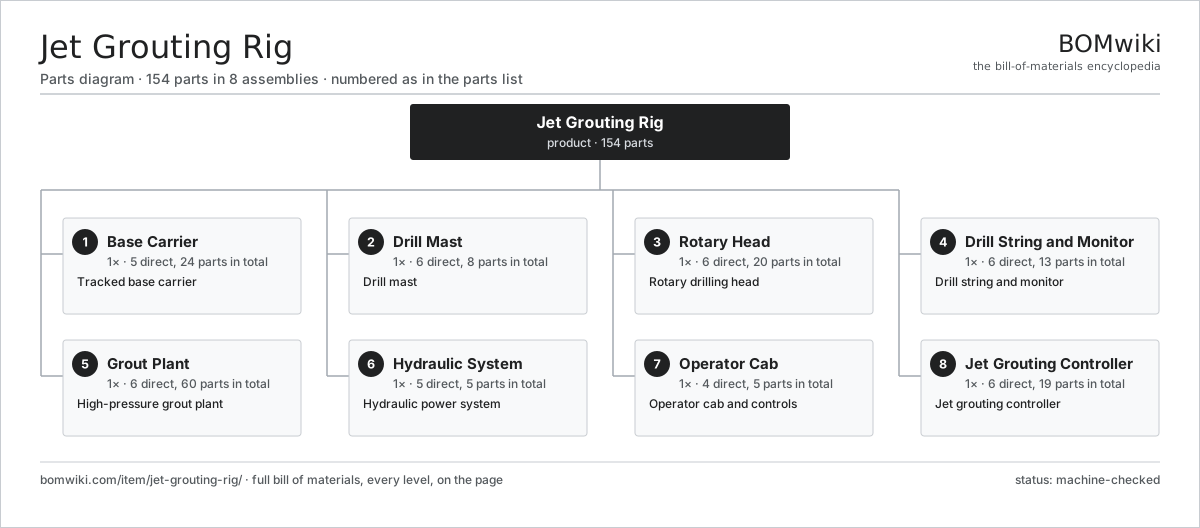
| # | Part | Qty | What it does |
|---|---|---|---|
| 1 | Base Carrier 5 parts | 1× | Tracked base carrier |
| 2 | Drill Mast 6 parts | 1× | Drill mast |
| 3 | Rotary Head 6 parts | 1× | Rotary drilling head |
| 4 | Drill String and Monitor 6 parts | 1× | Drill string and monitor |
| 5 | Grout Plant 6 parts | 1× | High-pressure grout plant |
| 6 | Hydraulic System 5 parts | 1× | Hydraulic power system |
| 7 | Operator Cab 4 parts | 1× | Operator cab and controls |
| 8 | Jet Grouting Controller 6 parts | 1× | Jet grouting controller |
3D model
No 3D model yet. Have a CAD file of this? Add a 3D model — STL renders right on this page; STEP, FreeCAD, and OpenSCAD sources are welcome too (openly licensed, like all 3D models on BOMwiki).
Build & assembly graph
expand / collapse · shared sub-assemblies converge · links to related products · est. labourTap an assembly to expand/collapse · tap a part to open it · use “Open page” for any node · drag to pan, scroll to zoom.
Bill of materials for Jet Grouting Rig
8 top-level lines · 74 rows shown · 154 parts total · indented to 3 levels| # | Item / sub-assembly | Part no. | Qty/assy | Ext. qty | Parts | Type |
|---|---|---|---|---|---|---|
| 1 | Base Carrier 5 parts | jet-grouting-rig-base-carrier | 1× | 1 | 24 | assembly |
| 1.1 | Track Frame | jet-grouting-rig-track-frame | 2× | 2 | · | part |
| 1.2 | Travel Motor 4 parts | jet-grouting-rig-track-motor | 2× | 2 | 6 | assembly |
| 1.2.1 | Gearbox Housing | gearbox-housing | 1× | 2 | · | part |
| 1.2.2 | Helical Gear Pair | gear-pair | 2× | 4 | · | part |
| 1.2.3 | Ball Bearing | ball-bearing | 2× | 4 | · | part |
| 1.2.4 | Oil Seal | oil-seal | 1× | 2 | · | part |
| 1.3 | Diesel Engine 3 parts | jet-grouting-rig-diesel-engine | 1× | 1 | 5 | assembly |
| 1.3.1 | Engine Block | jet-grouting-rig-engine-block | 1× | 1 | · | part |
| 1.3.2 | Cooling Package | jet-grouting-rig-radiator | 1× | 1 | · | part |
| 1.3.3 | Oil Seal | oil-seal | 3× | 3 | · | part |
| 1.4 | Outrigger | jet-grouting-rig-outrigger | 4× | 4 | · | part |
| 1.5 | Fastener Set | fastener-set | 1× | 1 | · | part |
| 2 | Drill Mast 6 parts | jet-grouting-rig-mast | 1× | 1 | 8 | assembly |
| 2.1 | Mast Frame | jet-grouting-rig-mast-frame | 1× | 1 | · | part |
| 2.2 | Feed Cylinder | jet-grouting-rig-feed-cylinder | 2× | 2 | · | part |
| 2.3 | Feed Chain | jet-grouting-rig-feed-chain | 1× | 1 | · | part |
| 2.4 | Head Carriage | jet-grouting-rig-guide-carriage | 1× | 1 | · | part |
| 2.5 | Mast Tilt Cylinder | jet-grouting-rig-mast-tilt | 2× | 2 | · | part |
| 2.6 | Fastener Set | fastener-set | 1× | 1 | · | part |
| 3 | Rotary Head 6 parts | jet-grouting-rig-rotary-head | 1× | 1 | 20 | assembly |
| 3.1 | Head Gearbox 4 parts | jet-grouting-rig-head-gearbox | 1× | 1 | 10 | assembly |
| 3.1.1 | Gearbox Housing | gearbox-housing | 1× | 1 | · | part |
| 3.1.2 | Helical Gear Pair | gear-pair | 3× | 3 | · | part |
| 3.1.3 | Ball Bearing | ball-bearing | 4× | 4 | · | part |
| 3.1.4 | Oil Seal | oil-seal | 2× | 2 | · | part |
| 3.2 | Head Motor | jet-grouting-rig-head-motor | 2× | 2 | · | part |
| 3.3 | Head Spindle | jet-grouting-rig-head-spindle | 1× | 1 | · | part |
| 3.4 | High-Pressure Swivel | jet-grouting-rig-swivel | 1× | 1 | · | part |
| 3.5 | Ball Bearing | ball-bearing | 4× | 4 | · | part |
| 3.6 | Oil Seal | oil-seal | 2× | 2 | · | part |
| 4 | Drill String and Monitor 6 parts | jet-grouting-rig-drill-string | 1× | 1 | 13 | assembly |
| 4.1 | Drill Rod | jet-grouting-rig-drill-rod | 6× | 6 | · | part |
| 4.2 | Jetting Monitor | jet-grouting-rig-monitor | 1× | 1 | · | part |
| 4.3 | Grout Nozzle | jet-grouting-rig-grout-nozzle | 2× | 2 | · | part |
| 4.4 | Air Nozzle | jet-grouting-rig-air-nozzle | 2× | 2 | · | part |
| 4.5 | Drill Bit | jet-grouting-rig-drill-bit | 1× | 1 | · | part |
| 4.6 | O-Ring Set | oring-set | 1× | 1 | · | part |
| 5 | Grout Plant 6 parts | jet-grouting-rig-grout-plant | 1× | 1 | 60 | assembly |
| 5.1 | Colloidal Mixer 3 parts | jet-grouting-rig-grout-mixer | 1× | 1 | 26 | assembly |
| 5.1.1 | Mixer Tank | jet-grouting-rig-mixer-tank | 1× | 1 | · | part |
| 5.1.2 | Servo Motor 4 parts + deeper › | servo-motor | 1× | 1 | 24 | assembly |
| 5.1.3 | Mixer Impeller | jet-grouting-rig-mixer-impeller | 1× | 1 | · | part |
| 5.2 | High-Pressure Pump 4 parts | jet-grouting-rig-hp-pump | 1× | 1 | 29 | assembly |
| 5.2.1 | Pump Fluid End | jet-grouting-rig-pump-block | 1× | 1 | · | part |
| 5.2.2 | Pump Plunger | jet-grouting-rig-pump-plunger | 3× | 3 | · | part |
| 5.2.3 | Servo Motor 4 parts + deeper › | servo-motor | 1× | 1 | 24 | assembly |
| 5.2.4 | O-Ring Set | oring-set | 1× | 1 | · | part |
| 5.3 | Air Compressor | jet-grouting-rig-air-compressor | 1× | 1 | · | part |
| 5.4 | Grout Hose | jet-grouting-rig-grout-hose | 1× | 1 | · | part |
| 5.5 | Flow Meter | jet-grouting-rig-flow-meter | 1× | 1 | · | part |
| 5.6 | Pressure Sensor | pressure-sensor | 2× | 2 | · | part |
| 6 | Hydraulic System 5 parts | jet-grouting-rig-hydraulics | 1× | 1 | 5 | assembly |
| 6.1 | Main Pump | jet-grouting-rig-main-pump | 1× | 1 | · | part |
| 6.2 | Valve Block | jet-grouting-rig-valve-block | 1× | 1 | · | part |
| 6.3 | Reservoir | jet-grouting-rig-reservoir | 1× | 1 | · | part |
| 6.4 | Oil Cooler | jet-grouting-rig-oil-cooler | 1× | 1 | · | part |
| 6.5 | O-Ring Set | oring-set | 1× | 1 | · | part |
| 7 | Operator Cab 4 parts | jet-grouting-rig-cab | 1× | 1 | 5 | assembly |
| 7.1 | Cab Shell | jet-grouting-rig-cab-shell | 1× | 1 | · | part |
| 7.2 | Operator Seat | jet-grouting-rig-seat | 1× | 1 | · | part |
| 7.3 | Control Joystick | jet-grouting-rig-joystick | 2× | 2 | · | part |
| 7.4 | LCD Panel | lcd-panel | 1× | 1 | · | part |
| 8 | Jet Grouting Controller 6 parts | jet-grouting-rig-control | 1× | 1 | 19 | assembly |
| 8.1 | Process Controller 4 parts | jet-grouting-rig-controller | 1× | 1 | 7 | assembly |
| 8.1.1 | Bare PCB | pcb-bare | 1× | 1 | · | part |
| 8.1.2 | Microcontroller | mcu | 1× | 1 | · | part |
| 8.1.3 | SMD Passive (R/C/L) | smd-passives | 1× | 1 | · | part |
| 8.1.4 | Relay | relay | 4× | 4 | · | part |
| 8.2 | Depth Encoder | jet-grouting-rig-depth-encoder | 1× | 1 | · | part |
| 8.3 | Rotation Sensor | jet-grouting-rig-rotation-sensor | 1× | 1 | · | part |
| 8.4 | Process Recorder | jet-grouting-rig-recorder | 1× | 1 | · | part |
| 8.5 | Wire Bundle | wire-bundle | 1× | 1 | · | part |
| 8.6 | Connector | connector | 8× | 8 | · | part |
Related products
same domain, ranked by shared parts Asphalt Recycler
226 parts · shares 21 with this page
Asphalt Recycler
226 parts · shares 21 with this page
 Bridge Girder Launching Gantry
1,542 parts · shares 21 with this page
Bridge Girder Launching Gantry
1,542 parts · shares 21 with this page
 Flat-Top Tower Crane
358 parts · shares 21 with this page
Flat-Top Tower Crane
358 parts · shares 21 with this page
 Ground Anchor Drill Rig
142 parts · shares 21 with this page
Ground Anchor Drill Rig
142 parts · shares 21 with this page
 Guardrail Installation Rig
320 parts · shares 21 with this page
Guardrail Installation Rig
320 parts · shares 21 with this page
 Segmental Bridge Erection Gantry
847 parts · shares 21 with this page
Segmental Bridge Erection Gantry
847 parts · shares 21 with this page
Sourcing: possible vendors
Prices, MOQ, and lead times are algorithmic estimates, not quotes, and not claims about these companies. Company mappings are curated by keyword; est. price band $15k–$2M. How estimates work| Vendor | HQ | Specialty | MOQ | Lead time |
|---|---|---|---|---|
| caterpillar.com ↗ | Irving, US | Construction & mining equipment | made to order | 16–28 wks |
|
🇯🇵Komatsu
komatsu.com ↗
|
Tokyo, JP | Construction & mining equipment | made to order | 16–28 wks |
|
🇸🇪Volvo CE
volvoce.com ↗
|
Gothenburg, SE | Construction equipment | made to order | 16–28 wks |
|
🇨🇭Liebherr
liebherr.com ↗
|
Bulle, CH | Cranes & heavy equipment | made to order | 16–28 wks |
|
🇨🇳XCMG
xcmg.com ↗
|
Xuzhou, CN | Construction machinery | made to order | 16–28 wks |
999-word article