Articulating Boom Lift
ProductOverview
An articulating boom lift, often called a knuckle boom, is a self-propelled aerial work platform that carries one or two workers up to a working height of 16-26 m. What sets it apart from a straight telescopic boom lift is the jointed Articulating Knuckle Joint in the middle of the boom. That joint folds and unfolds, so the platform can travel up and then back over an obstacle rather than only straight out. A worker can be lifted past a parapet, over a row of pipework, or in through a gap in a structure and still reach a point set back from the machine. The machine drives itself around a site on its own Drive Chassis and positions the boom over a full circle on the Turntable & Slew, so it works close in around buildings, plant, and steelwork where a scissor lift or a straight boom cannot reach.
The reach geometry is the product of three boom motions working together. The Lower Boom & Riser lifts the knuckle off the turntable, the knuckle folds the upper boom up and over, and the Upper Boom & Jib telescopes out to set the final horizontal distance. Throughout all of this the basket is held level, so the occupants stay upright no matter how the boom is folded.
Chassis and Stability
The Chassis Frame is a welded high-tensile steel box-section structure carrying the axles, the Cast Counterweight, and the slew ring. All four wheels drive and steer: each carries an Wheel Drive Motor with an integral Planetary Wheel Hub planetary reduction, and each wheel end is turned by an Steering Cylinder for two-wheel, four-wheel, and crab steering modes. The wheels are Foam-Filled Wheel foam-filled non-marking tyres that cannot puncture on site debris, and a Wheel Parking Brake on each holds the machine on grade when hydraulic pressure drops to zero.
A machine that lifts a person 25 m into the air has to stay upright. An Oscillating Axle keeps all four tyres loaded on rough ground while travelling, then locks out hydraulically once the boom is raised so the wheelbase becomes rigid. A Chassis Tilt Sensor reads chassis slope on two axes and inhibits boom functions if the machine is parked on more than about 3-5 degrees. The cast Cast Counterweight of 1.5-3 t keeps the combined centre of gravity inside the wheelbase at full outreach.
Turntable and Slew
The whole upper structure sits on the Slew Ring Bearing, a four-point-contact ball slewing bearing about 1 m across with internal gear teeth. The Slew Drive Gearbox is a self-locking worm-gear gearbox built around a Helical Gear Pair and Gearbox Housing, turned by a Slew Hydraulic Motor. Worm gearing is chosen because it holds position under load without a separate brake and gives the slow, controlled 360 degree rotation needed for fine positioning. Because the turntable rotates continuously, oil and signals cross the joint through a Rotary Manifold rather than through hoses that would wind up.
The Boom Linkage
The Lower Boom Section is pinned to the Turntable Weldment and raised by the Lower Lift Cylinder. Alongside it runs the Riser Parallel Linkage, a parallelogram that keeps the upper structure level as the lower boom rises. The Knuckle Weldment joins the lower boom to the upper boom, and the Knuckle Cylinder acting through a Knuckle Bell Crank bell crank folds the upper boom through about 135 degrees. That fold is what delivers the up-and-over clearance.
The Upper Boom Base Section carries the telescoping Upper Boom Fly Section, driven by the Telescope Cylinder and sliding on Boom Wear Pad pads. At the tip, an Articulating Jib swung by a Jib Cylinder gives a final 1.5 m of articulated reach for placing the basket precisely against a structure. A Cable & Hose Carrier energy chain carries hoses and wiring along the telescoping section without snagging. Every pin joint runs on a Boom Pivot Bushing to cut wear and grease intervals.
Platform and Leveling
The Platform Basket is a steel or aluminium cage with a 1.1 m guardrail, toeboards, and a self-closing gate, rated for 230-300 kg. It hangs from a Platform Rotator that swings it about plus or minus 80 degrees so the occupants can square up to the work. Leveling is automatic: a master cylinder at the boom heel is hydraulically linked to a slave Platform Level Cylinder at the platform, so as boom angles change the basket stays horizontal. The Platform Control Box box holds proportional joysticks, and a Foot Enable Switch must be held before any function responds. A Platform Load Cell disables motion if the basket is overloaded, and Lanyard Anchor points take the occupants fall-arrest lanyards.
Hydraulics and Power
The Main Hydraulic Pump is a variable-displacement piston pump delivering about 60 L/min at up to 240 bar, feeding the Proportional Valve Block proportional spools. A Counterbalance Valve on each boom cylinder holds the load and prevents runaway descent if a hose bursts. The Hydraulic Reservoir, Hydraulic Oil Cooler, and Hydraulic Hose Set complete the circuit, with Pressure Sensor units feeding load data back to the controllers. Power comes from either a Diesel Engine with a Diesel Fuel Tank for outdoor work or a Battery Pack and Electric Drive Motor for emission-free indoor use, cooled by the Engine Radiator on the diesel version, with a Power Supply for the control electronics.
Control and Safety
A Machine Control Unit arbitrates the platform and Ground Control Station inputs over CAN and drives the valves. The Envelope Limiter reads the Boom Angle Sensor and Telescope Length Sensor data along with platform load to keep the basket inside the rated reach envelope, slowing or stopping any motion that would push the machine toward instability. The ground station carries duplicate functions and an emergency-lower valve for rescuing an occupant, a Wire Bundle runs the harness from chassis to platform, and a Alarm & Beacon with motion alarm warns people working below.
Articulating Boom Lift parts and their functions
9 top-level parts · 120 parts in total · full bill of materials below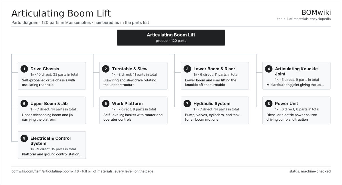
| # | Part | Qty | What it does |
|---|---|---|---|
| 1 | Drive Chassis 10 parts | 1× | Self-propelled drive chassis with oscillating rear axle |
| 2 | Turntable & Slew 8 parts | 1× | Slew ring and slew drive rotating the upper structure |
| 3 | Lower Boom & Riser 6 parts | 1× | Lower boom and riser lifting the knuckle off the turntable |
| 4 | Articulating Knuckle Joint 5 parts | 1× | Mid articulating joint giving the up-and-over reach |
| 5 | Upper Boom & Jib 7 parts | 1× | Upper telescoping boom and jib carrying the platform |
| 6 | Work Platform 7 parts | 1× | Self-leveling basket with rotator and operator controls |
| 7 | Hydraulic System 7 parts | 1× | Pump, valves, cylinders, and tank for all boom motions |
| 8 | Power Unit 6 parts | 1× | Diesel or electric power source driving pump and traction |
| 9 | Electrical & Control System 9 parts | 1× | Platform and ground control stations, sensors, and harness |
3D model
No 3D model yet. Have a CAD file of this? Add a 3D model — STL renders right on this page; STEP, FreeCAD, and OpenSCAD sources are welcome too (openly licensed, like all 3D models on BOMwiki).
Build & assembly graph
expand / collapse · shared sub-assemblies converge · links to related products · est. labourTap an assembly to expand/collapse · tap a part to open it · use “Open page” for any node · drag to pan, scroll to zoom.
Bill of materials for Articulating Boom Lift
9 top-level lines · 74 rows shown · 120 parts total · indented to 3 levels| # | Item / sub-assembly | Part no. | Qty/assy | Ext. qty | Parts | Type |
|---|---|---|---|---|---|---|
| 1 | Drive Chassis 10 parts | articulating-boom-lift-chassis | 1× | 1 | 32 | assembly |
| 1.1 | Chassis Frame | articulating-boom-lift-chassis-frame | 1× | 1 | · | part |
| 1.2 | Cast Counterweight | articulating-boom-lift-counterweight | 1× | 1 | · | part |
| 1.3 | Wheel Drive Motor | articulating-boom-lift-drive-motor | 4× | 4 | · | part |
| 1.4 | Planetary Wheel Hub | articulating-boom-lift-wheel-hub | 4× | 4 | · | part |
| 1.5 | Steering Cylinder | articulating-boom-lift-steer-cylinder | 4× | 4 | · | part |
| 1.6 | Oscillating Axle | articulating-boom-lift-oscillating-axle | 1× | 1 | · | part |
| 1.7 | Foam-Filled Wheel | articulating-boom-lift-wheel | 4× | 4 | · | part |
| 1.8 | Wheel Parking Brake | articulating-boom-lift-wheel-brake | 4× | 4 | · | part |
| 1.9 | Chassis Tilt Sensor | articulating-boom-lift-tilt-sensor | 1× | 1 | · | part |
| 1.10 | Ball Bearing | ball-bearing | 8× | 8 | · | part |
| 2 | Turntable & Slew 8 parts | articulating-boom-lift-turntable | 1× | 1 | 11 | assembly |
| 2.1 | Turntable Weldment | articulating-boom-lift-turntable-frame | 1× | 1 | · | part |
| 2.2 | Slew Ring Bearing | articulating-boom-lift-slew-ring | 1× | 1 | · | part |
| 2.3 | Slew Drive Gearbox | articulating-boom-lift-slew-drive | 1× | 1 | · | part |
| 2.4 | Slew Hydraulic Motor | articulating-boom-lift-slew-motor | 1× | 1 | · | part |
| 2.5 | Rotary Manifold | articulating-boom-lift-rotary-manifold | 1× | 1 | · | part |
| 2.6 | Gearbox Housing | gearbox-housing | 1× | 1 | · | part |
| 2.7 | Helical Gear Pair | gear-pair | 1× | 1 | · | part |
| 2.8 | Oil Seal | oil-seal | 4× | 4 | · | part |
| 3 | Lower Boom & Riser 6 parts | articulating-boom-lift-lower-boom | 1× | 1 | 11 | assembly |
| 3.1 | Lower Boom Section | articulating-boom-lift-lower-boom-section | 1× | 1 | · | part |
| 3.2 | Riser Parallel Linkage | articulating-boom-lift-riser-link | 1× | 1 | · | part |
| 3.3 | Lower Lift Cylinder | articulating-boom-lift-lift-cylinder | 1× | 1 | · | part |
| 3.4 | Boom Pivot Pin | articulating-boom-lift-lower-boom-pin | 2× | 2 | · | part |
| 3.5 | Boom Pivot Bushing | articulating-boom-lift-boom-bushing | 4× | 4 | · | part |
| 3.6 | O-Ring Set | oring-set | 2× | 2 | · | part |
| 4 | Articulating Knuckle Joint 5 parts | articulating-boom-lift-knuckle | 1× | 1 | 9 | assembly |
| 4.1 | Knuckle Weldment | articulating-boom-lift-knuckle-weldment | 1× | 1 | · | part |
| 4.2 | Knuckle Cylinder | articulating-boom-lift-knuckle-cylinder | 1× | 1 | · | part |
| 4.3 | Knuckle Pivot Pin | articulating-boom-lift-knuckle-pin | 2× | 2 | · | part |
| 4.4 | Knuckle Bell Crank | articulating-boom-lift-knuckle-link | 1× | 1 | · | part |
| 4.5 | Boom Pivot Bushing | articulating-boom-lift-boom-bushing | 4× | 4 | · | part |
| 5 | Upper Boom & Jib 7 parts | articulating-boom-lift-upper-boom | 1× | 1 | 14 | assembly |
| 5.1 | Upper Boom Base Section | articulating-boom-lift-upper-boom-base | 1× | 1 | · | part |
| 5.2 | Upper Boom Fly Section | articulating-boom-lift-upper-boom-fly | 1× | 1 | · | part |
| 5.3 | Telescope Cylinder | articulating-boom-lift-telescope-cylinder | 1× | 1 | · | part |
| 5.4 | Articulating Jib | articulating-boom-lift-jib | 1× | 1 | · | part |
| 5.5 | Jib Cylinder | articulating-boom-lift-jib-cylinder | 1× | 1 | · | part |
| 5.6 | Boom Wear Pad | articulating-boom-lift-boom-wear-pad | 8× | 8 | · | part |
| 5.7 | Cable & Hose Carrier | articulating-boom-lift-cable-track | 1× | 1 | · | part |
| 6 | Work Platform 7 parts | articulating-boom-lift-platform | 1× | 1 | 8 | assembly |
| 6.1 | Platform Basket | articulating-boom-lift-basket | 1× | 1 | · | part |
| 6.2 | Platform Rotator | articulating-boom-lift-platform-rotator | 1× | 1 | · | part |
| 6.3 | Platform Level Cylinder | articulating-boom-lift-level-cylinder | 1× | 1 | · | part |
| 6.4 | Platform Control Box | articulating-boom-lift-platform-control | 1× | 1 | · | part |
| 6.5 | Platform Load Cell | articulating-boom-lift-load-cell | 1× | 1 | · | part |
| 6.6 | Lanyard Anchor | articulating-boom-lift-lanyard-anchor | 2× | 2 | · | part |
| 6.7 | Foot Enable Switch | articulating-boom-lift-foot-switch | 1× | 1 | · | part |
| 7 | Hydraulic System 7 parts | articulating-boom-lift-hydraulics | 1× | 1 | 14 | assembly |
| 7.1 | Main Hydraulic Pump | articulating-boom-lift-main-pump | 1× | 1 | · | part |
| 7.2 | Proportional Valve Block | articulating-boom-lift-valve-block | 1× | 1 | · | part |
| 7.3 | Hydraulic Reservoir | articulating-boom-lift-hydraulic-tank | 1× | 1 | · | part |
| 7.4 | Counterbalance Valve | articulating-boom-lift-counterbalance-valve | 6× | 6 | · | part |
| 7.5 | Hydraulic Hose Set | articulating-boom-lift-hose-set | 1× | 1 | · | part |
| 7.6 | Pressure Sensor | pressure-sensor | 3× | 3 | · | part |
| 7.7 | Hydraulic Oil Cooler | articulating-boom-lift-oil-cooler | 1× | 1 | · | part |
| 8 | Power Unit 6 parts | articulating-boom-lift-power-unit | 1× | 1 | 6 | assembly |
| 8.1 | Diesel Engine | articulating-boom-lift-diesel-engine | 1× | 1 | · | part |
| 8.2 | Diesel Fuel Tank | articulating-boom-lift-fuel-tank | 1× | 1 | · | part |
| 8.3 | Electric Drive Motor | articulating-boom-lift-traction-motor | 1× | 1 | · | part |
| 8.4 | Battery Pack | articulating-boom-lift-battery-pack | 1× | 1 | · | part |
| 8.5 | Engine Radiator | articulating-boom-lift-radiator | 1× | 1 | · | part |
| 8.6 | Power Supply | power-supply | 1× | 1 | · | part |
| 9 | Electrical & Control System 9 parts | articulating-boom-lift-electrical | 1× | 1 | 15 | assembly |
| 9.1 | Ground Control Station | articulating-boom-lift-ground-control | 1× | 1 | · | part |
| 9.2 | Machine Control Unit | articulating-boom-lift-machine-ecu | 1× | 1 | · | part |
| 9.3 | Envelope Limiter | articulating-boom-lift-envelope-limiter | 1× | 1 | · | part |
| 9.4 | Boom Angle Sensor | articulating-boom-lift-angle-sensor | 3× | 3 | · | part |
| 9.5 | Telescope Length Sensor | articulating-boom-lift-length-sensor | 1× | 1 | · | part |
| 9.6 | Wire Bundle | wire-bundle | 1× | 1 | · | part |
| 9.7 | Alarm & Beacon | articulating-boom-lift-beacon | 1× | 1 | · | part |
| 9.8 | Microcontroller | mcu | 2× | 2 | · | part |
| 9.9 | Relay | relay | 4× | 4 | · | part |
Related products
same domain, ranked by shared parts Asphalt Recycler
226 parts · shares 7 with this page
Bridge Form Traveler
405 parts · shares 7 with this page
Asphalt Recycler
226 parts · shares 7 with this page
Bridge Form Traveler
405 parts · shares 7 with this page
 Bridge Girder Launching Gantry
1,542 parts · shares 7 with this page
Bridge Girder Launching Gantry
1,542 parts · shares 7 with this page
 Cold In-Place Recycling Train
657 parts · shares 7 with this page
Concrete Reclaimer Plant
154 parts · shares 7 with this page
Cold In-Place Recycling Train
657 parts · shares 7 with this page
Concrete Reclaimer Plant
154 parts · shares 7 with this page
 Diaphragm Wall Cutter
440 parts · shares 7 with this page
Diaphragm Wall Cutter
440 parts · shares 7 with this page
Sourcing: possible vendors
Prices, MOQ, and lead times are algorithmic estimates, not quotes, and not claims about these companies. Company mappings are curated by keyword; est. price band $15k–$2M. How estimates work| Vendor | HQ | Specialty | MOQ | Lead time |
|---|---|---|---|---|
| caterpillar.com ↗ | Irving, US | Construction & mining equipment | made to order | 16–28 wks |
|
🇯🇵Komatsu
komatsu.com ↗
|
Tokyo, JP | Construction & mining equipment | made to order | 16–28 wks |
|
🇸🇪Volvo CE
volvoce.com ↗
|
Gothenburg, SE | Construction equipment | made to order | 16–28 wks |
|
🇨🇭Liebherr
liebherr.com ↗
|
Bulle, CH | Cranes & heavy equipment | made to order | 16–28 wks |
|
🇨🇳XCMG
xcmg.com ↗
|
Xuzhou, CN | Construction machinery | made to order | 16–28 wks |
1,139-word article