Flat-Top Tower Crane
ProductOverview
The flat-top tower crane, also called a topless tower crane, is a saddle-jib crane built without the A-frame and tower peak that sit above the slewing platform on a conventional hammerhead crane. On a hammerhead crane the jib and counter-jib are held up by pendant bars that run from their ends to the top of an A-frame above the slew. The flat-top design removes that A-frame and carries the bending moment inside the depth of the jib and counter-jib themselves, using in-plane Jib Tie Bar members rather than overhead pendants. The result is a crane whose highest point is the top of the horizontal jib rather than a peak several metres above it.
The crane lifts loads by spooling wire rope on the Main Hoist Winch, moving them in and out along the Horizontal Load Jib with the Trolley System, and rotating the whole upper structure on the Slewing Unit. Capacities typically run from 8 to 25 tonnes at the inner radius, with tip loads of 1.5 to 4 tonnes at jib lengths of 50 to 80 metres.
Why Flat-Top Helps on Crowded Sites
The defining benefit shows up when several cranes work the same site. Large buildings are often served by three, four or more tower cranes whose jibs sweep overlapping circles. To avoid collisions the cranes are set at different heights so one jib passes over another. On a hammerhead crane the height that matters for clearance is not the jib, it is the top of the A-frame, which can stand 4 to 8 metres above the jib. Every overlapping crane has to be raised that much higher to clear the peak of its neighbour.
The flat-top crane has no peak above the jib, so the vertical gap needed between two overlapping cranes drops to roughly the depth of the jib plus a safety margin. Across a stack of several cranes the saving compounds. Each crane can sit lower, which means fewer Mast Section units in each tower, lower freestanding mast loads, and in many cases one or two fewer building ties over the life of the job. On a tight urban plot where cranes also have to stay under aircraft height limits or planning height caps, removing the peak is sometimes the only way to fit the cranes that the schedule needs.
Assembly and Erection
The absence of the A-frame also makes the crane easier to put up. The Flat-Top Connection Frame joins the Horizontal Load Jib and Counter-Jib & Counterweight roots directly across the slew with a stiff Connection Box Girder, so there are no pendant bars to thread, no A-frame to raise, and no tower peak to pin in mid-air. The jib and counter-jib arrive in a small number of pre-assembled sections that bolt together on the ground using the Jib End Connector lugs, then lift as two clean horizontal pieces. A mobile crane of modest size can erect a flat-top because no single lift includes the height or awkward geometry of an A-frame assembly.
For tall buildings the crane raises itself. The Climbing Cage surrounds the mast and uses a long-stroke Climbing Cylinder fed by the Hydraulic Power Pack to jack the entire upper crane up by one mast height. A new Mast Section is then rolled in and pinned at the base of the cage. The same cage supports internal climbing, where the crane sits inside the building core and climbs on the finished floor slabs as construction rises.
Slewing Unit and Load Path
The Slewing Unit is the rotating heart of the crane. A large geared Slew Bearing Ring, 1.5 to 2.5 metres across, carries the combined axial, radial and overturning loads while letting the upper works turn freely. Two Slew Drive Unit units mesh pinions against the Slew Gear Rim and use variable-frequency control through the Slew VFD so the crane accelerates gently, which keeps a swinging load from building dangerous momentum. When the crane is out of service the Slew Brake releases so the jib can weathervane and present the smallest face to the wind.
The load path is direct. Weight on the Lifting Hook pulls the Main Hoist Rope over the Trolley Sheave and back to the Hoist Rope Drum. The jib reacts that load as bending, carried by its top and bottom Jib Main Chord members and the in-plane ties, then into the Turntable Platform, through the slew ring, and down the Tower Mast to the Foundation & Base.
Trolley, Hoist and Hook
Radial positioning comes from the Trolley Carriage, a four-wheel carriage running on the Trolley Running Track along the lower jib chords. The Trolley Travel Winch pulls it in and out at 20 to 40 metres per minute using a looped Trolley Travel Rope returned around the Jib Tip Sheave. Lifting is done by the Main Hoist Winch, whose Hoist Motor drives the drum through the Hoist Gearbox at reductions of 30:1 to 60:1. The Hook Block can be reeved with two falls for fast light lifts or four falls for the rated heavy lift at half the speed.
Counterweight and Balance
The Counter-Jib & Counterweight sits opposite the load jib and carries both the hoist winch and a stack of Counterweight Slab units, 20 to 60 tonnes in total, held in the Counterweight Tray. The counterweight is matched to the chosen jib length so the moment about the slew stays balanced through the working range. A Trim Ballast Block block trims the balance when the jib is shortened. The Foundation & Base adds Base Ballast Block on a Cruciform Cross Base to keep the freestanding crane stable against overturning.
Control and Safety
Operation runs from the Operator Cab, where the driver uses Control Joystick inputs read by the Safety PLC. The Load Moment Indicator continuously computes load times radius from the Radius Encoder and a hoist Pressure Sensor, and it cuts outward trolley travel and hoisting before the crane exceeds its load chart. A mast-top Anemometer warns the driver and inhibits lifts once wind passes the in-service limit of about 20 metres per second. All three motions are driven from the VFD & Control Cabinet, fed by the Site Power Supply at 400 volts three phase.
Flat-Top Tower Crane parts and their functions
9 top-level parts · 358 parts in total · full bill of materials below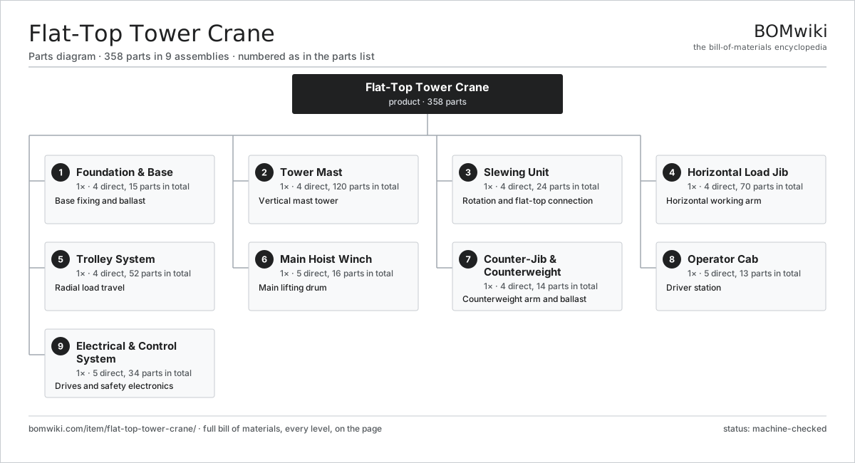
| # | Part | Qty | What it does |
|---|---|---|---|
| 1 | Foundation & Base 4 parts | 1× | Base fixing and ballast |
| 2 | Tower Mast 4 parts | 1× | Vertical mast tower |
| 3 | Slewing Unit 4 parts | 1× | Rotation and flat-top connection |
| 4 | Horizontal Load Jib 4 parts | 1× | Horizontal working arm |
| 5 | Trolley System 4 parts | 1× | Radial load travel |
| 6 | Main Hoist Winch 5 parts | 1× | Main lifting drum |
| 7 | Counter-Jib & Counterweight 4 parts | 1× | Counterweight arm and ballast |
| 8 | Operator Cab 5 parts | 1× | Driver station |
| 9 | Electrical & Control System 5 parts | 1× | Drives and safety electronics |
3D model
No 3D model yet. Have a CAD file of this? Add a 3D model — STL renders right on this page; STEP, FreeCAD, and OpenSCAD sources are welcome too (openly licensed, like all 3D models on BOMwiki).
Build & assembly graph
expand / collapse · shared sub-assemblies converge · links to related products · est. labourTap an assembly to expand/collapse · tap a part to open it · use “Open page” for any node · drag to pan, scroll to zoom.
Bill of materials for Flat-Top Tower Crane
9 top-level lines · 112 rows shown · 358 parts total · indented to 3 levels| # | Item / sub-assembly | Part no. | Qty/assy | Ext. qty | Parts | Type |
|---|---|---|---|---|---|---|
| 1 | Foundation & Base 4 parts | flat-top-tower-crane-foundation | 1× | 1 | 15 | assembly |
| 1.1 | Cruciform Cross Base 3 parts | flat-top-tower-crane-cross-base | 1× | 1 | 9 | assembly |
| 1.1.1 | Base Box Beam | flat-top-tower-crane-base-beam | 4× | 4 | · | part |
| 1.1.2 | Corner Bearing Pad | flat-top-tower-crane-corner-pad | 4× | 4 | · | part |
| 1.1.3 | Fastener Set | fastener-set | 1× | 1 | · | part |
| 1.2 | Cast-In Fixing Anchor | flat-top-tower-crane-fixing-anchors | 4× | 4 | · | part |
| 1.3 | Base Ballast Block | flat-top-tower-crane-base-ballast | 1× | 1 | · | part |
| 1.4 | Fastener Set | fastener-set | 1× | 1 | · | part |
| 2 | Tower Mast 4 parts | flat-top-tower-crane-mast | 1× | 1 | 120 | assembly |
| 2.1 | Mast Section 3 parts | flat-top-tower-crane-mast-section | 8× | 8 | 13 | assembly |
| 2.1.1 | Mast Corner Chord | flat-top-tower-crane-mast-chord | 4× | 32 | · | part |
| 2.1.2 | Mast Lacing Set | flat-top-tower-crane-mast-lacing | 1× | 8 | · | part |
| 2.1.3 | Section End Connector | flat-top-tower-crane-mast-connector | 8× | 64 | · | part |
| 2.2 | Climbing Cage 4 parts | flat-top-tower-crane-climbing-cage | 1× | 1 | 13 | assembly |
| 2.2.1 | Climbing Cage Frame | flat-top-tower-crane-cage-frame | 1× | 1 | · | part |
| 2.2.2 | Climbing Cylinder 3 parts + deeper › | flat-top-tower-crane-climbing-cylinder | 1× | 1 | 3 | assembly |
| 2.2.3 | Hydraulic Power Pack 4 parts + deeper › | flat-top-tower-crane-hydraulic-power-pack | 1× | 1 | 5 | assembly |
| 2.2.4 | Mast Guide Roller | flat-top-tower-crane-section-rollers | 4× | 4 | · | part |
| 2.3 | Building Tie Frame | flat-top-tower-crane-tie-frame | 2× | 2 | · | part |
| 2.4 | Fastener Set | fastener-set | 1× | 1 | · | part |
| 3 | Slewing Unit 4 parts | flat-top-tower-crane-slewing-unit | 1× | 1 | 24 | assembly |
| 3.1 | Slew Bearing Ring 4 parts | flat-top-tower-crane-slew-ring | 1× | 1 | 5 | assembly |
| 3.1.1 | Bearing Race | flat-top-tower-crane-bearing-race | 1× | 1 | · | part |
| 3.1.2 | Ball Bearing | ball-bearing | 1× | 1 | · | part |
| 3.1.3 | Slew Gear Rim | flat-top-tower-crane-slew-gear-rim | 1× | 1 | · | part |
| 3.1.4 | Oil Seal | oil-seal | 2× | 2 | · | part |
| 3.2 | Slew Drive Unit 5 parts | flat-top-tower-crane-slew-drive | 2× | 2 | 6 | assembly |
| 3.2.1 | Slew Motor | flat-top-tower-crane-slew-motor | 1× | 2 | · | part |
| 3.2.2 | Gearbox Housing | gearbox-housing | 1× | 2 | · | part |
| 3.2.3 | Helical Gear Pair | gear-pair | 2× | 4 | · | part |
| 3.2.4 | Slew Pinion | flat-top-tower-crane-slew-pinion | 1× | 2 | · | part |
| 3.2.5 | Slew Brake | flat-top-tower-crane-slew-brake | 1× | 2 | · | part |
| 3.3 | Turntable Platform | flat-top-tower-crane-turntable | 1× | 1 | · | part |
| 3.4 | Flat-Top Connection Frame 3 parts | flat-top-tower-crane-flat-top-frame | 1× | 1 | 6 | assembly |
| 3.4.1 | Connection Box Girder | flat-top-tower-crane-connection-box | 1× | 1 | · | part |
| 3.4.2 | Jib Root Pin | flat-top-tower-crane-root-pin | 4× | 4 | · | part |
| 3.4.3 | Fastener Set | fastener-set | 1× | 1 | · | part |
| 4 | Horizontal Load Jib 4 parts | flat-top-tower-crane-load-jib | 1× | 1 | 70 | assembly |
| 4.1 | Jib Section 3 parts | flat-top-tower-crane-jib-section | 6× | 6 | 10 | assembly |
| 4.1.1 | Jib Main Chord | flat-top-tower-crane-jib-chord | 3× | 18 | · | part |
| 4.1.2 | Jib Lacing Set | flat-top-tower-crane-jib-lacing | 1× | 6 | · | part |
| 4.1.3 | Jib End Connector | flat-top-tower-crane-jib-connector | 6× | 36 | · | part |
| 4.2 | Jib Tie Bar | flat-top-tower-crane-jib-tie-bar | 4× | 4 | · | part |
| 4.3 | Jib Tip Section 3 parts | flat-top-tower-crane-jib-tip | 1× | 1 | 5 | assembly |
| 4.3.1 | Jib Tip Sheave | flat-top-tower-crane-tip-sheave | 2× | 2 | · | part |
| 4.3.2 | Jib End Stop | flat-top-tower-crane-jib-end-stop | 1× | 1 | · | part |
| 4.3.3 | Ball Bearing | ball-bearing | 2× | 2 | · | part |
| 4.4 | Trolley Running Track | flat-top-tower-crane-trolley-track | 1× | 1 | · | part |
| 5 | Trolley System 4 parts | flat-top-tower-crane-trolley-system | 1× | 1 | 52 | assembly |
| 5.1 | Trolley Carriage 4 parts | flat-top-tower-crane-trolley | 1× | 1 | 15 | assembly |
| 5.1.1 | Trolley Frame | flat-top-tower-crane-trolley-frame | 1× | 1 | · | part |
| 5.1.2 | Trolley Wheel | flat-top-tower-crane-trolley-wheel | 4× | 4 | · | part |
| 5.1.3 | Trolley Sheave | flat-top-tower-crane-trolley-sheave | 2× | 2 | · | part |
| 5.1.4 | Ball Bearing | ball-bearing | 8× | 8 | · | part |
| 5.2 | Trolley Travel Winch 3 parts | flat-top-tower-crane-trolley-winch | 1× | 1 | 26 | assembly |
| 5.2.1 | Trolley Rope Drum | flat-top-tower-crane-trolley-drum | 1× | 1 | · | part |
| 5.2.2 | Servo Motor 4 parts + deeper › | servo-motor | 1× | 1 | 24 | assembly |
| 5.2.3 | Helical Gear Pair | gear-pair | 1× | 1 | · | part |
| 5.3 | Trolley Travel Rope | flat-top-tower-crane-trolley-rope | 1× | 1 | · | part |
| 5.4 | Hook Block 4 parts | flat-top-tower-crane-hook-block | 1× | 1 | 10 | assembly |
| 5.4.1 | Lifting Hook | flat-top-tower-crane-hook | 1× | 1 | · | part |
| 5.4.2 | Hook Block Sheave | flat-top-tower-crane-block-sheave | 4× | 4 | · | part |
| 5.4.3 | Hook Safety Latch | flat-top-tower-crane-safety-latch | 1× | 1 | · | part |
| 5.4.4 | Ball Bearing | ball-bearing | 4× | 4 | · | part |
| 6 | Main Hoist Winch 5 parts | flat-top-tower-crane-hoist-winch | 1× | 1 | 16 | assembly |
| 6.1 | Hoist Rope Drum | flat-top-tower-crane-hoist-drum | 1× | 1 | · | part |
| 6.2 | Hoist Motor | flat-top-tower-crane-hoist-motor | 1× | 1 | · | part |
| 6.3 | Hoist Gearbox 4 parts | flat-top-tower-crane-hoist-gearbox | 1× | 1 | 12 | assembly |
| 6.3.1 | Helical Gear Pair | gear-pair | 3× | 3 | · | part |
| 6.3.2 | Gearbox Housing | gearbox-housing | 1× | 1 | · | part |
| 6.3.3 | Ball Bearing | ball-bearing | 6× | 6 | · | part |
| 6.3.4 | Oil Seal | oil-seal | 2× | 2 | · | part |
| 6.4 | Hoist Brake | flat-top-tower-crane-hoist-brake | 1× | 1 | · | part |
| 6.5 | Main Hoist Rope | flat-top-tower-crane-hoist-rope | 1× | 1 | · | part |
| 7 | Counter-Jib & Counterweight 4 parts | flat-top-tower-crane-counter-jib | 1× | 1 | 14 | assembly |
| 7.1 | Counter-Jib Frame 3 parts | flat-top-tower-crane-counter-jib-frame | 1× | 1 | 6 | assembly |
| 7.1.1 | Counter-Jib Chord | flat-top-tower-crane-counter-jib-chord | 4× | 4 | · | part |
| 7.1.2 | Counter-Jib Lacing | flat-top-tower-crane-counter-jib-lacing | 1× | 1 | · | part |
| 7.1.3 | Access Handrail Set | flat-top-tower-crane-handrail-set | 1× | 1 | · | part |
| 7.2 | Counterweight Slab | flat-top-tower-crane-counterweight-slab | 6× | 6 | · | part |
| 7.3 | Counterweight Tray | flat-top-tower-crane-counterweight-tray | 1× | 1 | · | part |
| 7.4 | Trim Ballast Block | flat-top-tower-crane-counterweight-ballast | 1× | 1 | · | part |
| 8 | Operator Cab 5 parts | flat-top-tower-crane-operator-cab | 1× | 1 | 13 | assembly |
| 8.1 | Cab Shell 3 parts | flat-top-tower-crane-cab-shell | 1× | 1 | 6 | assembly |
| 8.1.1 | Sheet Metal Panel | sheet-panel | 4× | 4 | · | part |
| 8.1.2 | Cab Glazing Set | flat-top-tower-crane-cab-glazing | 1× | 1 | · | part |
| 8.1.3 | Fastener Set | fastener-set | 1× | 1 | · | part |
| 8.2 | Operator Seat | flat-top-tower-crane-operator-seat | 1× | 1 | · | part |
| 8.3 | Control Joystick | flat-top-tower-crane-control-joystick | 2× | 2 | · | part |
| 8.4 | LCD Panel | lcd-panel | 1× | 1 | · | part |
| 8.5 | Cab HVAC Unit 3 parts | flat-top-tower-crane-cab-hvac | 1× | 1 | 3 | assembly |
| 8.5.1 | Heating Element | heating-element | 1× | 1 | · | part |
| 8.5.2 | HVAC Blower | flat-top-tower-crane-hvac-blower | 1× | 1 | · | part |
| 8.5.3 | Power Supply | power-supply | 1× | 1 | · | part |
| 9 | Electrical & Control System 5 parts | flat-top-tower-crane-control-system | 1× | 1 | 34 | assembly |
| 9.1 | VFD & Control Cabinet 6 parts | flat-top-tower-crane-vfd-cabinet | 1× | 1 | 24 | assembly |
| 9.1.1 | Hoist VFD | flat-top-tower-crane-hoist-vfd | 1× | 1 | · | part |
| 9.1.2 | Trolley VFD | flat-top-tower-crane-trolley-vfd | 1× | 1 | · | part |
| 9.1.3 | Slew VFD | flat-top-tower-crane-slew-vfd | 1× | 1 | · | part |
| 9.1.4 | Safety PLC 4 parts + deeper › | flat-top-tower-crane-plc | 1× | 1 | 7 | assembly |
| 9.1.5 | Relay | relay | 6× | 6 | · | part |
| 9.1.6 | Connector | connector | 8× | 8 | · | part |
| 9.2 | Load Moment Indicator 3 parts | flat-top-tower-crane-lmi | 1× | 1 | 3 | assembly |
| 9.2.1 | Pressure Sensor | pressure-sensor | 1× | 1 | · | part |
| 9.2.2 | Radius Encoder | flat-top-tower-crane-radius-sensor | 1× | 1 | · | part |
| 9.2.3 | LCD Panel | lcd-panel | 1× | 1 | · | part |
| 9.3 | Anemometer | flat-top-tower-crane-anemometer | 1× | 1 | · | part |
| 9.4 | Site Power Supply 3 parts | flat-top-tower-crane-power-supply | 1× | 1 | 3 | assembly |
| 9.4.1 | Power Supply | power-supply | 1× | 1 | · | part |
| 9.4.2 | Main Breaker | flat-top-tower-crane-main-breaker | 1× | 1 | · | part |
| 9.4.3 | Control Transformer | flat-top-tower-crane-transformer | 1× | 1 | · | part |
| 9.5 | Wire Bundle | wire-bundle | 3× | 3 | · | part |
Related products
same domain, ranked by shared parts Tracked Asphalt Paver
1,299 parts · shares 24 with this page
Tracked Asphalt Paver
1,299 parts · shares 24 with this page
 Asphalt Recycler
226 parts · shares 23 with this page
Asphalt Recycler
226 parts · shares 23 with this page
 Bridge Girder Launching Gantry
1,542 parts · shares 23 with this page
Bridge Girder Launching Gantry
1,542 parts · shares 23 with this page
 Segmental Bridge Erection Gantry
847 parts · shares 23 with this page
Segmental Bridge Erection Gantry
847 parts · shares 23 with this page
 Tandem Vibratory Roller
369 parts · shares 23 with this page
Tandem Vibratory Roller
369 parts · shares 23 with this page
 Cold In-Place Recycling Train
657 parts · shares 22 with this page
Cold In-Place Recycling Train
657 parts · shares 22 with this page
Sourcing: possible vendors
Prices, MOQ, and lead times are algorithmic estimates, not quotes, and not claims about these companies. Company mappings are curated by keyword; est. price band $15k–$2M. How estimates work| Vendor | HQ | Specialty | MOQ | Lead time |
|---|---|---|---|---|
| caterpillar.com ↗ | Irving, US | Construction & mining equipment | made to order | 16–28 wks |
|
🇯🇵Komatsu
komatsu.com ↗
|
Tokyo, JP | Construction & mining equipment | made to order | 16–28 wks |
|
🇸🇪Volvo CE
volvoce.com ↗
|
Gothenburg, SE | Construction equipment | made to order | 16–28 wks |
|
🇨🇭Liebherr
liebherr.com ↗
|
Bulle, CH | Cranes & heavy equipment | made to order | 16–28 wks |
|
🇨🇳XCMG
xcmg.com ↗
|
Xuzhou, CN | Construction machinery | made to order | 16–28 wks |
1,240-word article