Shoring Tower
ProductAlso known as: falsework tower, shoring, props tower
Overview
A shoring tower is temporary falsework that holds formwork and wet concrete at the correct level until the slab or beam above has cured and can carry itself. It is built from a modular standard-and-ledger kit: vertical legs slot into adjustable jacks at the bottom, horizontal ledgers and diagonal braces lock the legs into a rigid box, and fork heads at the top cradle the primary beams that carry the deck. The same parts assemble into a single light tower or a continuous grid of towers under a large soffit.
This entry describes a ring-lock system, where each Standard tube carries welded Ring rosette rings at 0.5 m centres. Eight openings in every ring accept ledger and brace ends at fixed and free angles, so a connection can be made anywhere on the leg without loose couplers. Cup-lock and frame systems differ in the joint detail but share the same load path: jack, standard, head, beam, deck.
Standards and ledgers
The legs of one tower are four Leg frame columns. Each column is built from a 3 m Standard tube with a 1 m Short standard tube above it, stacked through a Connector spigot and locked with a Spigot pin set so the joint cannot lift during the pour. A Standard end cap closes the top tube against water.
Horizontal members come as a Ledger set per lift. A Ledger tube carries a forged Ledger blade at each end; the blade drops into a rosette opening and a captive Ledger wedge is hammered home to draw the joint tight. Wedged blades give a connection that resists both tension and moment, which is what squares the tower and stops the legs from spreading. Ledgers run on all four faces at each level so the tower reads as a stack of rigid frames rather than four free-standing columns.
Jacks and heads
Adjustment happens at both ends of the leg. At the bottom a Base jack takes a Jack spindle running through a Jack adjusting nut, turned by a Jack handle to level the tower over uneven ground. Its Base bearing plate spreads the leg load onto sole timbers. The standard seats onto the spindle through a Base collar, pinned with a Collar pin and held by a Collar clip.
At the top the U-head jack uses the same spindle and nut but ends in a Fork head, a U-shaped cradle that locates and centres the Primary beam girders. A Fork retaining pin traps the beams in the fork so they cannot lift or walk sideways. Between them the two jacks give roughly 150–700 mm of fine adjustment, enough to dial the deck to its design soffit level after the tower is stood and braced.
Load on the deck passes into the Secondary beam joists, which sit at 300–500 mm centres across two Primary beam girders. The primary beams bear in the fork heads, so the whole slab load funnels down four legs into four base jacks and into the ground.
Bracing and stability
A tower this slender is stable only when it is braced. Face bracing uses a Diagonal brace on the open faces: a Brace tube with a Swivel coupler at each end that pins to a rosette and locks with a Brace wedge. Bracing on alternate lifts in both directions turns the stack into a triangulated frame that can take the wind and the out-of-plumb loads that come with site work.
At the base a Plan brace runs horizontally across the footprint to stop the legs racking before the diagonals are in. Where towers stand in a grid, a Tie tube laces neighbours together with right-angle Right-angle coupler clamps, so a row of towers shares load and bracing rather than acting alone. The leg safe working load printed on the data plate assumes this bracing is present: an unbraced or part-braced tower has a far lower capacity and must never be loaded.
A mobile variant swaps the base jacks for a Castor set. A Castor wheel on a swivel Castor swivel bearing lets the tower roll into position, a threaded Castor stem gives height adjustment, and a Castor brake locks both wheel and swivel before anyone climbs or loads the tower.
Erection and striking
Towers are built from the ground up. Crews set the base jacks on sole timbers, fit the bottom standards through their collars, then add ledgers and braces lift by lift, checking plumb and level as the stack grows. Spigot pins go in at every joint. The fork heads and primary beams go on last, and the jacks are wound to bring the deck to its final level before any concrete is placed.
Before anyone works at height the platform is fitted out for safety: a Guard rail set gives edge protection on the deck, an Access set provides a hook-on ladder and trap hatch to climb through the tower, and a Deck set of plywood panels and bearers forms the slab soffit. Every tower carries an Identification plate stamping its load class and last inspection date.
Striking is the reverse and is done in a controlled order. The jacks are wound down a few turns to ease the deck off the cured slab, the primary and secondary beams are lowered and removed, and the tower is taken apart in the order it was built. Ring-lock parts strip quickly because the wedges knock free with a hammer and no threaded couplers have to be undone. Because the kit reuses one Jack spindle design in both the base and U-head, and one rosette pattern across every standard, a yard can hold a small parts list and still build towers of many heights and footprints.
Shoring Tower parts and their functions
16 top-level parts · 353 parts in total · full bill of materials below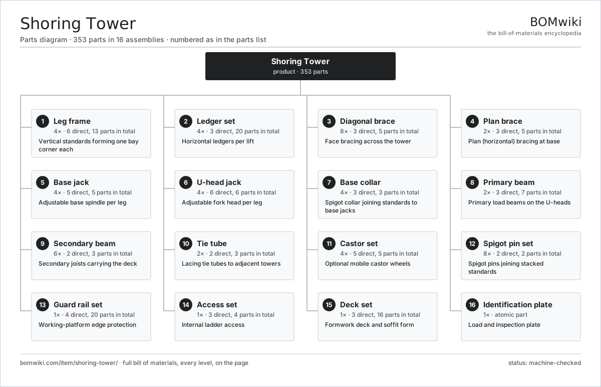
| # | Part | Qty | What it does |
|---|---|---|---|
| 1 | Leg frame 6 parts | 4× | Vertical standards forming one bay corner each |
| 2 | Ledger set 3 parts | 4× | Horizontal ledgers per lift |
| 3 | Diagonal brace 3 parts | 8× | Face bracing across the tower |
| 4 | Plan brace 3 parts | 2× | Plan (horizontal) bracing at base |
| 5 | Base jack 5 parts | 4× | Adjustable base spindle per leg |
| 6 | U-head jack 6 parts | 4× | Adjustable fork head per leg |
| 7 | Base collar 3 parts | 4× | Spigot collar joining standards to base jacks |
| 8 | Primary beam 3 parts | 2× | Primary load beams on the U-heads |
| 9 | Secondary beam 2 parts | 6× | Secondary joists carrying the deck |
| 10 | Tie tube 2 parts | 2× | Lacing tie tubes to adjacent towers |
| 11 | Castor set 5 parts | 4× | Optional mobile castor wheels |
| 12 | Spigot pin set 2 parts | 8× | Spigot pins joining stacked standards |
| 13 | Guard rail set 4 parts | 1× | Working-platform edge protection |
| 14 | Access set 3 parts | 1× | Internal ladder access |
| 15 | Deck set 3 parts | 1× | Formwork deck and soffit form |
| 16 | Identification plate | 1× | Load and inspection plate |
Diagrams & photos

.jpg)
3D model
No 3D model yet. Have a CAD file of this? Add a 3D model — STL renders right on this page; STEP, FreeCAD, and OpenSCAD sources are welcome too (openly licensed, like all 3D models on BOMwiki).
Build & assembly graph
expand / collapse · shared sub-assemblies converge · links to related products · est. labourTap an assembly to expand/collapse · tap a part to open it · use “Open page” for any node · drag to pan, scroll to zoom.
Bill of materials for Shoring Tower
16 top-level lines · 69 rows shown · 353 parts total · indented to 3 levels| # | Item / sub-assembly | Part no. | Qty/assy | Ext. qty | Parts | Type |
|---|---|---|---|---|---|---|
| 1 | Leg frame 6 parts | st-leg-frame | 4× | 4 | 13 | assembly |
| 1.1 | Standard tube | st-standard-tube | 1× | 4 | · | part |
| 1.2 | Short standard tube | st-standard-tube-short | 1× | 4 | · | part |
| 1.3 | Ring rosette | st-rosette | 7× | 28 | · | part |
| 1.4 | Connector spigot | st-spigot | 2× | 8 | · | part |
| 1.5 | Standard end cap | st-standard-cap | 1× | 4 | · | part |
| 1.6 | Fastener Set | fastener-set | 1× | 4 | · | part |
| 2 | Ledger set 3 parts | st-ledger-set | 4× | 4 | 20 | assembly |
| 2.1 | Ledger tube | st-ledger-tube | 4× | 16 | · | part |
| 2.2 | Ledger blade | st-ledger-blade | 8× | 32 | · | part |
| 2.3 | Ledger wedge | st-ledger-wedge | 8× | 32 | · | part |
| 3 | Diagonal brace 3 parts | st-diagonal-brace | 8× | 8 | 5 | assembly |
| 3.1 | Brace tube | st-brace-tube | 1× | 8 | · | part |
| 3.2 | Swivel coupler | st-brace-coupler | 2× | 16 | · | part |
| 3.3 | Brace wedge | st-brace-wedge | 2× | 16 | · | part |
| 4 | Plan brace 3 parts | st-plan-brace | 2× | 2 | 5 | assembly |
| 4.1 | Plan brace tube | st-plan-brace-tube | 1× | 2 | · | part |
| 4.2 | Swivel coupler | st-brace-coupler | 2× | 4 | · | part |
| 4.3 | Brace wedge | st-brace-wedge | 2× | 4 | · | part |
| 5 | Base jack 5 parts | st-base-jack | 4× | 4 | 5 | assembly |
| 5.1 | Jack spindle | st-jack-spindle | 1× | 4 | · | part |
| 5.2 | Jack adjusting nut | st-jack-nut | 1× | 4 | · | part |
| 5.3 | Jack handle | st-jack-handle | 1× | 4 | · | part |
| 5.4 | Base bearing plate | st-base-plate | 1× | 4 | · | part |
| 5.5 | Fastener Set | fastener-set | 1× | 4 | · | part |
| 6 | U-head jack 6 parts | st-u-head-jack | 4× | 4 | 6 | assembly |
| 6.1 | Jack spindle | st-jack-spindle | 1× | 4 | · | part |
| 6.2 | Jack adjusting nut | st-jack-nut | 1× | 4 | · | part |
| 6.3 | Jack handle | st-jack-handle | 1× | 4 | · | part |
| 6.4 | Fork head | st-fork-head | 1× | 4 | · | part |
| 6.5 | Fork retaining pin | st-fork-pin | 1× | 4 | · | part |
| 6.6 | Fastener Set | fastener-set | 1× | 4 | · | part |
| 7 | Base collar 3 parts | st-base-collar | 4× | 4 | 3 | assembly |
| 7.1 | Collar sleeve | st-collar-sleeve | 1× | 4 | · | part |
| 7.2 | Collar pin | st-collar-pin | 1× | 4 | · | part |
| 7.3 | Collar clip | st-collar-clip | 1× | 4 | · | part |
| 8 | Primary beam 3 parts | st-primary-beam | 2× | 2 | 7 | assembly |
| 8.1 | Primary beam body | st-primary-beam-web | 1× | 2 | · | part |
| 8.2 | Beam end cap | st-beam-end-cap | 2× | 4 | · | part |
| 8.3 | Beam nail plate | st-beam-nail-plate | 4× | 8 | · | part |
| 9 | Secondary beam 2 parts | st-secondary-beam | 6× | 6 | 3 | assembly |
| 9.1 | Secondary beam body | st-secondary-beam-web | 1× | 6 | · | part |
| 9.2 | Beam end cap | st-beam-end-cap | 2× | 12 | · | part |
| 10 | Tie tube 2 parts | st-tie-tube | 2× | 2 | 3 | assembly |
| 10.1 | Tie tube member | st-tie-tube-member | 1× | 2 | · | part |
| 10.2 | Right-angle coupler | st-tie-coupler | 2× | 4 | · | part |
| 11 | Castor set 5 parts | st-castor-set | 4× | 4 | 5 | assembly |
| 11.1 | Castor wheel | st-castor-wheel | 1× | 4 | · | part |
| 11.2 | Castor stem | st-castor-stem | 1× | 4 | · | part |
| 11.3 | Castor brake | st-castor-brake | 1× | 4 | · | part |
| 11.4 | Castor swivel bearing | st-castor-bearing | 1× | 4 | · | part |
| 11.5 | Fastener Set | fastener-set | 1× | 4 | · | part |
| 12 | Spigot pin set 2 parts | st-spigot-pin-set | 8× | 8 | 2 | assembly |
| 12.1 | Spigot pin | st-spigot-pin | 1× | 8 | · | part |
| 12.2 | Spigot clip | st-spigot-clip | 1× | 8 | · | part |
| 13 | Guard rail set 4 parts | st-guard-rail-set | 1× | 1 | 20 | assembly |
| 13.1 | Guard post | st-guard-post | 4× | 4 | · | part |
| 13.2 | Guard rail | st-guard-rail | 4× | 4 | · | part |
| 13.3 | Toe board | st-toe-board | 4× | 4 | · | part |
| 13.4 | Guard rail clip | st-guard-clip | 8× | 8 | · | part |
| 14 | Access set 3 parts | st-access-set | 1× | 1 | 4 | assembly |
| 14.1 | Access ladder | st-access-ladder | 1× | 1 | · | part |
| 14.2 | Access hatch | st-access-hatch | 1× | 1 | · | part |
| 14.3 | Ladder hook | st-access-hook | 2× | 2 | · | part |
| 15 | Deck set 3 parts | st-deck-set | 1× | 1 | 16 | assembly |
| 15.1 | Deck panel | st-deck-panel | 4× | 4 | · | part |
| 15.2 | Deck bearer | st-deck-bearer | 4× | 4 | · | part |
| 15.3 | Deck hold-down clip | st-deck-clip | 8× | 8 | · | part |
| 16 | Identification plate | st-id-plate | 1× | 1 | · | part |
Sourcing: possible vendors
Prices, MOQ, and lead times are algorithmic estimates, not quotes, and not claims about these companies. Company mappings are curated by keyword; est. price band $15k–$2M. How estimates work| Vendor | HQ | Specialty | MOQ | Lead time |
|---|---|---|---|---|
| caterpillar.com ↗ | Irving, US | Construction & mining equipment | made to order | 16–28 wks |
|
🇯🇵Komatsu
komatsu.com ↗
|
Tokyo, JP | Construction & mining equipment | made to order | 16–28 wks |
|
🇸🇪Volvo CE
volvoce.com ↗
|
Gothenburg, SE | Construction equipment | made to order | 16–28 wks |
|
🇨🇭Liebherr
liebherr.com ↗
|
Bulle, CH | Cranes & heavy equipment | made to order | 16–28 wks |
|
🇨🇳XCMG
xcmg.com ↗
|
Xuzhou, CN | Construction machinery | made to order | 16–28 wks |
1,000-word article