Grout Mixing and Pumping Plant
ProductOverview
A grout mixing and pumping plant batches cement grout and injects it under pressure into the ground, into structural cavities, or behind tunnel linings. The plant pairs a high-shear Colloidal Mixing Tank with an agitated Agitated Holding Tank and a Grout Injection Pump, all carried on one Skid Frame and run from a single Control Panel.
The work splits into two flows. The mixer turns dry cement, water, and admixtures into a stable colloidal grout. The pump then takes grout from the holding tank and delivers it to the work face at a controlled rate and pressure. Splitting mixing from pumping lets the mixer prepare the next batch while the pump empties the previous one, so injection runs continuously instead of stopping between batches.
Typical jobs include ground consolidation, anchor and rock-bolt grouting, void filling, annulus grouting around pipes, and post-tensioning duct grouting. Output and pressure are set to suit the application, from low-pressure void fill to high-pressure permeation grouting.
Colloidal mixing
The Colloidal Mixing Tank is what makes the grout stable. A centrifugal Colloidal Pump draws grout from the bottom of the Mixing Vessel and forces it back in through a tangential return, setting up a strong vortex. Inside the Pump Volute the grout passes through a narrow gap against a Shear Disc spinning at 1500-2000 rpm.
That high shear wets every cement grain and breaks up the dry agglomerates that a paddle mixer leaves behind. The result is a colloidal grout that resists bleed and stays in suspension far longer than paddle-mixed grout. A 200-500 litre batch is fully mixed in roughly 30-90 seconds, so a plant can prepare several cubic metres of grout per hour.
Water is added first through the Water Dosing System system so the Water Flow Meter can set a repeatable water-cement ratio, commonly 0.4-0.7 by weight. Cement and any admixtures are then charged into the spinning batch. When mixing is complete the Mixer Discharge Valve opens and the batch drops into the holding tank.
Holding and agitation
The Agitated Holding Tank buffers several batches so the pump never runs dry. Even a good colloidal grout will start to settle if left still, so a slow Agitator Paddle turns at 30-60 rpm on a Agitator Shaft to keep the solids in suspension without whipping air into the mix.
A Suction Strainer on the pump suction stops oversize lumps from reaching the Grout Injection Pump. A Level Float Switch tells the controller when the tank is low, so the operator knows when to mix again, and a Flush and Drain Port lets the tank be washed out at the end of a shift before the grout sets.
Injection pump
The Grout Injection Pump is usually a progressive cavity pump. A single-helix Helical Rotor turns inside a double-helix Rubber Stator, forming sealed cavities that carry grout from suction to discharge. The flow is near continuous with low pulsation, which suits permeation grouting where steady pressure matters. A Pulsation Damper smooths what little pulsation remains.
Output is typically 20-80 l/min, set by the pump speed through a VFD on the Injection Pump Motor. Working pressure runs from a few bar for void fill up to 40 bar for tight ground, with peaks near 60 bar. A Pressure Relief Valve returns grout to the Feed Hopper if the line blocks, and a Pressure Sensor on the discharge feeds pressure back to the Control Panel so the operator can hold a target injection pressure. Some plants use a piston pump instead, which reaches higher pressure but delivers a more pulsed flow.
Grout leaves the pump through the Delivery Hose Kit: steel-braided Grout Hose rated to 40 bar, joined by Cam-Lock Coupling fittings and ending in a Injection Nozzle or packer at the borehole.
Materials and construction
The wetted tanks are mild steel with an epoxy lining to resist the abrasion and alkalinity of cement grout. The Shear Disc and Pump Volute are the fastest-wearing parts and are made from hardened tool steel and cast iron so they hold their shear gap. The Rubber Stator is bonded NBR rubber and is treated as a consumable, since the chrome-plated rotor running against it wears the elastomer over time.
The Skid Frame is welded structural steel with Lifting Lug and Fork Pocket so the whole plant can be craned or forked into position on site. The Drive System uses IE3 motors, Helical Gear Pair reduction in cast Gearbox Housing casings, and a Drive Belt to the colloidal pump.
Use and variants
In operation the cycle repeats: dose water, charge cement, shear-mix the batch, drop it to the holding tank, then inject while the next batch mixes. The Control Panel runs the motor starters, holds the dosing logic, and shows pressure and flow so the operator can match the grout take of the ground.
Plant sizes range from compact single-bag units for anchor grouting up to high-output skids for tunnelling. Variants differ mainly in pump choice (progressive cavity for steady flow, piston for high pressure), tank volume, and whether dosing is manual or fully automatic through the PLC. Most plants run on a 0.4-0.7 water-cement ratio, but the colloidal mixer can also handle stiffer mixes and sanded grouts when the application calls for them.
Grout Mixing and Pumping Plant parts and their functions
8 top-level parts · 104 parts in total · full bill of materials below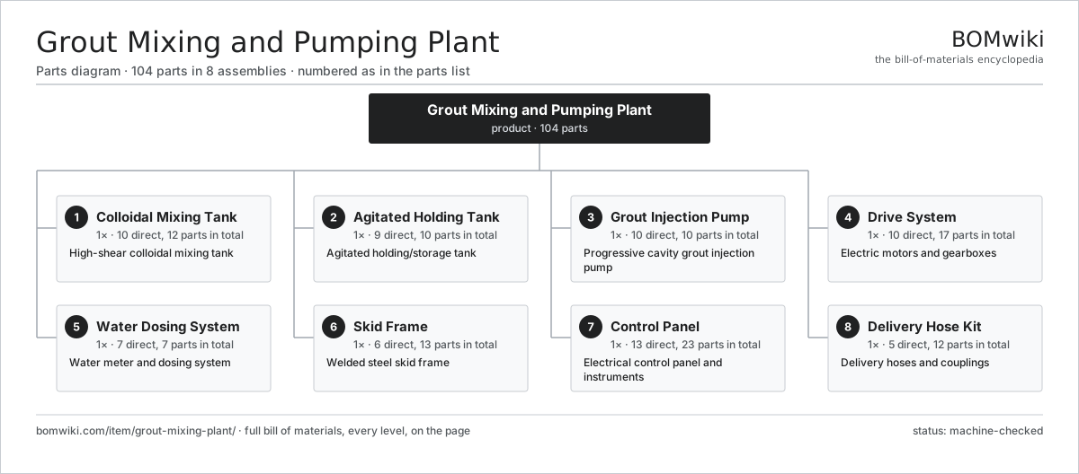
| # | Part | Qty | What it does |
|---|---|---|---|
| 1 | Colloidal Mixing Tank 10 parts | 1× | High-shear colloidal mixing tank |
| 2 | Agitated Holding Tank 9 parts | 1× | Agitated holding/storage tank |
| 3 | Grout Injection Pump 10 parts | 1× | Progressive cavity grout injection pump |
| 4 | Drive System 10 parts | 1× | Electric motors and gearboxes |
| 5 | Water Dosing System 7 parts | 1× | Water meter and dosing system |
| 6 | Skid Frame 6 parts | 1× | Welded steel skid frame |
| 7 | Control Panel 13 parts | 1× | Electrical control panel and instruments |
| 8 | Delivery Hose Kit 5 parts | 1× | Delivery hoses and couplings |
3D model
No 3D model yet. Have a CAD file of this? Add a 3D model — STL renders right on this page; STEP, FreeCAD, and OpenSCAD sources are welcome too (openly licensed, like all 3D models on BOMwiki).
Build & assembly graph
expand / collapse · shared sub-assemblies converge · links to related products · est. labourTap an assembly to expand/collapse · tap a part to open it · use “Open page” for any node · drag to pan, scroll to zoom.
Bill of materials for Grout Mixing and Pumping Plant
8 top-level lines · 78 rows shown · 104 parts total · indented to 3 levels| # | Item / sub-assembly | Part no. | Qty/assy | Ext. qty | Parts | Type |
|---|---|---|---|---|---|---|
| 1 | Colloidal Mixing Tank 10 parts | grout-mixing-plant-colloidal-mixer | 1× | 1 | 12 | assembly |
| 1.1 | Mixing Vessel | grout-mixing-plant-mixer-tank | 1× | 1 | · | part |
| 1.2 | Colloidal Pump | grout-mixing-plant-colloidal-pump | 1× | 1 | · | part |
| 1.3 | Pump Volute | grout-mixing-plant-mixer-volute | 1× | 1 | · | part |
| 1.4 | Shear Disc | grout-mixing-plant-shear-disc | 1× | 1 | · | part |
| 1.5 | Pump Shaft | grout-mixing-plant-mixer-shaft | 1× | 1 | · | part |
| 1.6 | Mixer Discharge Valve | grout-mixing-plant-mixer-discharge-valve | 1× | 1 | · | part |
| 1.7 | Ball Bearing | ball-bearing | 2× | 2 | · | part |
| 1.8 | Oil Seal | oil-seal | 2× | 2 | · | part |
| 1.9 | O-Ring Set | oring-set | 1× | 1 | · | part |
| 1.10 | Fastener Set | fastener-set | 1× | 1 | · | part |
| 2 | Agitated Holding Tank 9 parts | grout-mixing-plant-holding-tank | 1× | 1 | 10 | assembly |
| 2.1 | Holding Vessel | grout-mixing-plant-holding-vessel | 1× | 1 | · | part |
| 2.2 | Agitator Paddle | grout-mixing-plant-agitator-paddle | 1× | 1 | · | part |
| 2.3 | Agitator Shaft | grout-mixing-plant-agitator-shaft | 1× | 1 | · | part |
| 2.4 | Suction Strainer | grout-mixing-plant-suction-strainer | 1× | 1 | · | part |
| 2.5 | Level Float Switch | grout-mixing-plant-level-float | 1× | 1 | · | part |
| 2.6 | Flush and Drain Port | grout-mixing-plant-flush-port | 1× | 1 | · | part |
| 2.7 | Ball Bearing | ball-bearing | 2× | 2 | · | part |
| 2.8 | Oil Seal | oil-seal | 1× | 1 | · | part |
| 2.9 | Fastener Set | fastener-set | 1× | 1 | · | part |
| 3 | Grout Injection Pump 10 parts | grout-mixing-plant-injection-pump | 1× | 1 | 10 | assembly |
| 3.1 | Helical Rotor | grout-mixing-plant-pc-rotor | 1× | 1 | · | part |
| 3.2 | Rubber Stator | grout-mixing-plant-pc-stator | 1× | 1 | · | part |
| 3.3 | Feed Hopper | grout-mixing-plant-pump-hopper | 1× | 1 | · | part |
| 3.4 | Coupling Rod | grout-mixing-plant-pump-coupling-rod | 1× | 1 | · | part |
| 3.5 | Suction Housing | grout-mixing-plant-pump-suction-housing | 1× | 1 | · | part |
| 3.6 | Pressure Relief Valve | grout-mixing-plant-pressure-relief-valve | 1× | 1 | · | part |
| 3.7 | Pulsation Damper | grout-mixing-plant-pulsation-damper | 1× | 1 | · | part |
| 3.8 | Pressure Sensor | pressure-sensor | 1× | 1 | · | part |
| 3.9 | O-Ring Set | oring-set | 1× | 1 | · | part |
| 3.10 | Fastener Set | fastener-set | 1× | 1 | · | part |
| 4 | Drive System 10 parts | grout-mixing-plant-drive-system | 1× | 1 | 17 | assembly |
| 4.1 | Colloidal Pump Motor | grout-mixing-plant-mixer-motor | 1× | 1 | · | part |
| 4.2 | Injection Pump Motor | grout-mixing-plant-pump-motor | 1× | 1 | · | part |
| 4.3 | Agitator Motor | grout-mixing-plant-agitator-motor | 1× | 1 | · | part |
| 4.4 | Gearbox Housing | gearbox-housing | 2× | 2 | · | part |
| 4.5 | Helical Gear Pair | gear-pair | 2× | 2 | · | part |
| 4.6 | Drive Belt | drive-belt | 1× | 1 | · | part |
| 4.7 | Belt Guard | grout-mixing-plant-belt-guard | 1× | 1 | · | part |
| 4.8 | Ball Bearing | ball-bearing | 4× | 4 | · | part |
| 4.9 | Oil Seal | oil-seal | 3× | 3 | · | part |
| 4.10 | Fastener Set | fastener-set | 1× | 1 | · | part |
| 5 | Water Dosing System 7 parts | grout-mixing-plant-water-dosing | 1× | 1 | 7 | assembly |
| 5.1 | Water Flow Meter | grout-mixing-plant-water-meter | 1× | 1 | · | part |
| 5.2 | Dosing Solenoid Valve | grout-mixing-plant-water-solenoid | 1× | 1 | · | part |
| 5.3 | Water Booster Pump | grout-mixing-plant-water-pump | 1× | 1 | · | part |
| 5.4 | Inlet Strainer | grout-mixing-plant-water-filter | 1× | 1 | · | part |
| 5.5 | Flow Indicator | grout-mixing-plant-flow-gauge | 1× | 1 | · | part |
| 5.6 | O-Ring Set | oring-set | 1× | 1 | · | part |
| 5.7 | Fastener Set | fastener-set | 1× | 1 | · | part |
| 6 | Skid Frame 6 parts | grout-mixing-plant-skid-frame | 1× | 1 | 13 | assembly |
| 6.1 | Base Frame | grout-mixing-plant-base-channel | 1× | 1 | · | part |
| 6.2 | Lifting Lug | grout-mixing-plant-lifting-lugs | 4× | 4 | · | part |
| 6.3 | Tank Cradle | grout-mixing-plant-tank-cradle | 2× | 2 | · | part |
| 6.4 | Sheet Metal Panel | sheet-panel | 3× | 3 | · | part |
| 6.5 | Fork Pocket | grout-mixing-plant-fork-pockets | 2× | 2 | · | part |
| 6.6 | Fastener Set | fastener-set | 1× | 1 | · | part |
| 7 | Control Panel 13 parts | grout-mixing-plant-control-panel | 1× | 1 | 23 | assembly |
| 7.1 | Panel Enclosure | grout-mixing-plant-enclosure | 1× | 1 | · | part |
| 7.2 | PLC Controller | grout-mixing-plant-plc | 1× | 1 | · | part |
| 7.3 | Motor Starter | grout-mixing-plant-motor-starter | 3× | 3 | · | part |
| 7.4 | Operator Interface | grout-mixing-plant-hmi | 1× | 1 | · | part |
| 7.5 | Discharge Pressure Gauge | grout-mixing-plant-pressure-gauge | 1× | 1 | · | part |
| 7.6 | Batch Counter | grout-mixing-plant-batch-counter | 1× | 1 | · | part |
| 7.7 | Power Supply | power-supply | 1× | 1 | · | part |
| 7.8 | Microcontroller | mcu | 1× | 1 | · | part |
| 7.9 | Bare PCB | pcb-bare | 1× | 1 | · | part |
| 7.10 | SMD Passive (R/C/L) | smd-passives | 1× | 1 | · | part |
| 7.11 | Relay | relay | 4× | 4 | · | part |
| 7.12 | Connector | connector | 6× | 6 | · | part |
| 7.13 | Wire Bundle | wire-bundle | 1× | 1 | · | part |
| 8 | Delivery Hose Kit 5 parts | grout-mixing-plant-hose-kit | 1× | 1 | 12 | assembly |
| 8.1 | Grout Hose | grout-mixing-plant-grout-hose | 2× | 2 | · | part |
| 8.2 | Cam-Lock Coupling | grout-mixing-plant-camlock-coupling | 4× | 4 | · | part |
| 8.3 | Injection Nozzle | grout-mixing-plant-injection-nozzle | 1× | 1 | · | part |
| 8.4 | Hose Clamp | grout-mixing-plant-hose-clamp | 4× | 4 | · | part |
| 8.5 | Fastener Set | fastener-set | 1× | 1 | · | part |
Related products
same domain, ranked by shared parts Luffing Jib Tower Crane
1,807 parts · shares 12 with this page
Luffing Jib Tower Crane
1,807 parts · shares 12 with this page
 Mobile Concrete Plant
1,245 parts · shares 12 with this page
Mobile Concrete Plant
1,245 parts · shares 12 with this page
 Ring-Mounted Heavy Crane
2,831 parts · shares 12 with this page
Ring-Mounted Heavy Crane
2,831 parts · shares 12 with this page
 Tandem Vibratory Roller
369 parts · shares 12 with this page
Tandem Vibratory Roller
369 parts · shares 12 with this page
 Crawler Tractor
1,361 parts · shares 11 with this page
Crawler Tractor
1,361 parts · shares 11 with this page
Sourcing: possible vendors
Prices, MOQ, and lead times are algorithmic estimates, not quotes, and not claims about these companies. Company mappings are curated by keyword; est. price band $15k–$2M. How estimates work| Vendor | HQ | Specialty | MOQ | Lead time |
|---|---|---|---|---|
| caterpillar.com ↗ | Irving, US | Construction & mining equipment | made to order | 16–28 wks |
|
🇯🇵Komatsu
komatsu.com ↗
|
Tokyo, JP | Construction & mining equipment | made to order | 16–28 wks |
|
🇸🇪Volvo CE
volvoce.com ↗
|
Gothenburg, SE | Construction equipment | made to order | 16–28 wks |
|
🇨🇭Liebherr
liebherr.com ↗
|
Bulle, CH | Cranes & heavy equipment | made to order | 16–28 wks |
|
🇨🇳XCMG
xcmg.com ↗
|
Xuzhou, CN | Construction machinery | made to order | 16–28 wks |
1,005-word article