Rebar Shearing and Bending Line
ProductOverview
A rebar shearing and bending line turns a coil of reinforcing steel into the cut, straight, and bent bars that a building site needs, working from a digital bar schedule rather than by hand. Coil bar is cheaper than straight stock and produces almost no offcut waste, but it arrives curved and must be pulled off the coil, flattened, measured, cut to length, and often bent into stirrups or links before it can be tied into a cage. This line does all of that in one pass and at a rate no manual bench can match, which is why precast plants and large rebar shops run them around the clock.
The bar travels through the line in order. The Decoiler and Feed pays it off the coil and pushes it forward, the Straightening Head flattens it, the Length Measuring System system counts off the length, the Hydraulic Shear crops it, and the Bending Head forms any bends. Finished bars drop onto the Output Table table. The Hydraulic Power Unit unit powers the shear and bender, the Control Cabinet cabinet runs the sequence from the cut list, and the Frame and Guarding holds it all in alignment and fences it from the operator.
Decoiling and feeding
The coil sits on the Coil Cradle, a powered turntable that carries two to three tonnes of bar and turns under the pull of the line. A Decoiler Motor drives the cradle so it pays off bar at the right rate, and a Loop Sensor watches the slack loop between the cradle and the line so the two stay matched. Past the loop, a pair of grooved Pinch Roll rolls grip the bar and drag it into the line by friction, driven through the Feed Gearbox. Feeding is the step that sets throughput, so the rolls grip hard and the gearbox is sized to pull bar at speeds up to two metres per second.
Straightening
Coil bar holds the curve of the coil, so it must be flattened before it can be cut to a true length. The Straightening Head passes the bar through two offset rows of hardened Straightening Roller rollers held in a Roller Cassette. The rollers bend the bar past its yield point first one way then the other, with each cycle smaller than the last, so the bar leaves the head straight rather than springing back. Each roller has a Roller Adjuster that sets how deeply it presses, which is how the operator tunes the head to the bar diameter. Heavier lines use a spinning Rotary Straightening Rotor that straightens bar coming off the coil in any plane, which gives a straighter result on large diameters.
Measuring, shearing, and bending
Length is set by the Length Measuring System system. A friction Measuring Wheel rides on the bar and turns an Encoder that counts the length fed, and for short cuts a movable End Stop driven by a Ball Screw on a Linear Guide Rail gives a hard reference. When the programmed length has passed, the Hydraulic Shear fires. Its Shear Cylinder drives the Moving Blade down past the Fixed Blade, cropping the bar with a clean square end; the blade gap is set by shimming the Blade Holder blocks. For bent shapes the Bending Head takes over: a Servo Motor turns the Bending Table so the Bending Pin wraps the bar around the Center Mandrel, and the Bend Angle Encoder reads back the true angle so the controller can correct for springback.
Hydraulics and control
The Hydraulic Power Unit unit supplies the force for cutting and bending. A Hydraulic Pump driven by the Pump Motor draws from the Oil Reservoir and feeds the Valve Manifold, while a Accumulator stores a fast pressure surge for the shear stroke and Pressure Sensor units watch the line. The Control Cabinet cabinet runs the whole sequence: a PLC and I/O imports the bar schedule, an HMI Panel shows the operator each shape and quantity, and Servo Drive units run the bend and stop axes. A hard-wired Emergency Stop Circuit circuit drops pressure and motion if anything goes wrong, backed by the Light Curtain barriers in the Frame and Guarding.
Output and use
Finished bars leave the shear onto the Output Table table, where a Roller Bench supports long bars and a Collection Bin gathers them by shape or length, tipped clear by the Tipping Cylinder. From there bars go to a tying bay to be made into cages or stirrups. The line earns its place on volume and accuracy: it works straight from the structural engineer's bar schedule, holds cut length to a millimetre or two, wastes almost no steel because it works from coil, and runs far faster than cutting and bending bar by hand. Smaller shops run a single combined cut-and-bend machine, while precast plants run several of these lines in parallel feeding a stirrup welder or a cage-welding station downstream.
Rebar Shearing and Bending Line parts and their functions
9 top-level parts · 361 parts in total · full bill of materials below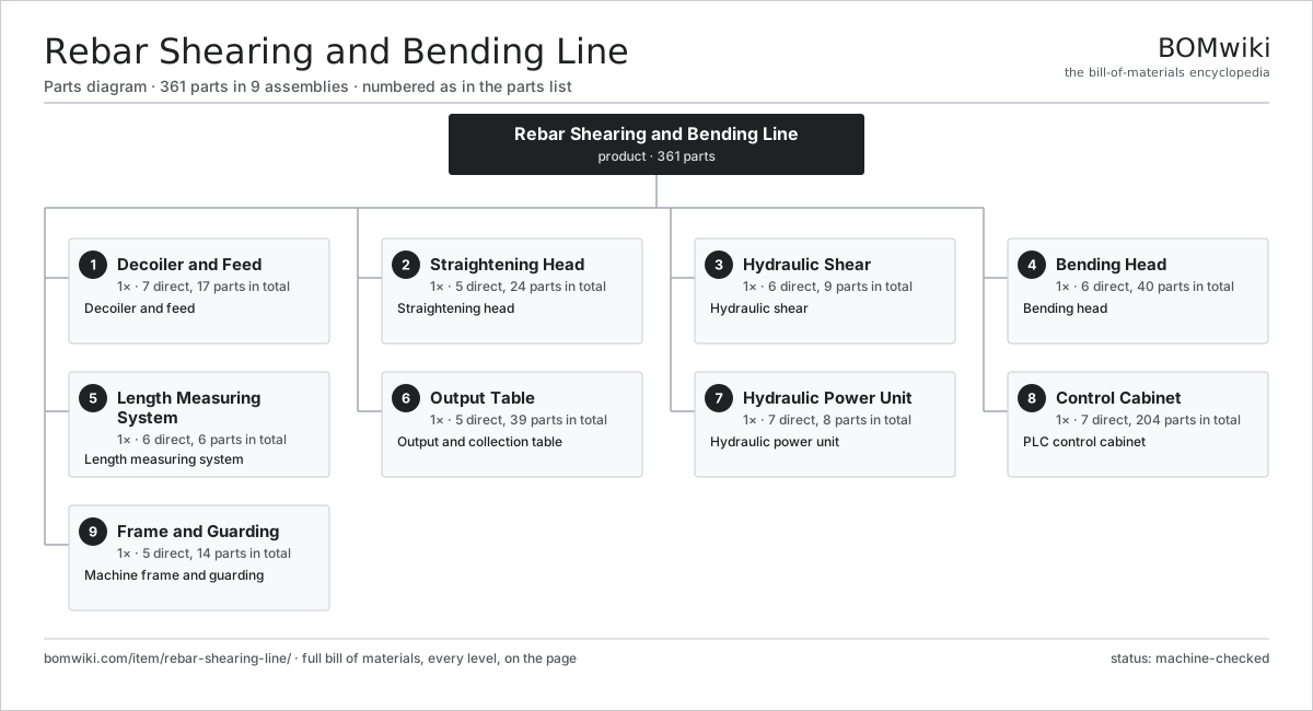
| # | Part | Qty | What it does |
|---|---|---|---|
| 1 | Decoiler and Feed 7 parts | 1× | Decoiler and feed |
| 2 | Straightening Head 5 parts | 1× | Straightening head |
| 3 | Hydraulic Shear 6 parts | 1× | Hydraulic shear |
| 4 | Bending Head 6 parts | 1× | Bending head |
| 5 | Length Measuring System 6 parts | 1× | Length measuring system |
| 6 | Output Table 5 parts | 1× | Output and collection table |
| 7 | Hydraulic Power Unit 7 parts | 1× | Hydraulic power unit |
| 8 | Control Cabinet 7 parts | 1× | PLC control cabinet |
| 9 | Frame and Guarding 5 parts | 1× | Machine frame and guarding |
3D model
No 3D model yet. Have a CAD file of this? Add a 3D model — STL renders right on this page; STEP, FreeCAD, and OpenSCAD sources are welcome too (openly licensed, like all 3D models on BOMwiki).
Build & assembly graph
expand / collapse · shared sub-assemblies converge · links to related products · est. labourTap an assembly to expand/collapse · tap a part to open it · use “Open page” for any node · drag to pan, scroll to zoom.
Bill of materials for Rebar Shearing and Bending Line
9 top-level lines · 88 rows shown · 361 parts total · indented to 3 levels| # | Item / sub-assembly | Part no. | Qty/assy | Ext. qty | Parts | Type |
|---|---|---|---|---|---|---|
| 1 | Decoiler and Feed 7 parts | rebar-shearing-line-decoiler | 1× | 1 | 17 | assembly |
| 1.1 | Coil Cradle | rebar-shearing-line-coil-cradle | 1× | 1 | · | part |
| 1.2 | Decoiler Motor | rebar-shearing-line-decoiler-motor | 1× | 1 | · | part |
| 1.3 | Pinch Roll | rebar-shearing-line-pinch-roll | 2× | 2 | · | part |
| 1.4 | Feed Gearbox 3 parts | rebar-shearing-line-feed-gearbox | 1× | 1 | 5 | assembly |
| 1.4.1 | Helical Gear Pair | gear-pair | 2× | 2 | · | part |
| 1.4.2 | Gearbox Housing | gearbox-housing | 1× | 1 | · | part |
| 1.4.3 | Oil Seal | oil-seal | 2× | 2 | · | part |
| 1.5 | Loop Sensor | rebar-shearing-line-loop-sensor | 1× | 1 | · | part |
| 1.6 | Ball Bearing | ball-bearing | 6× | 6 | · | part |
| 1.7 | Fastener Set | fastener-set | 1× | 1 | · | part |
| 2 | Straightening Head 5 parts | rebar-shearing-line-straightener | 1× | 1 | 24 | assembly |
| 2.1 | Straightening Roller | rebar-shearing-line-straighten-roll | 7× | 7 | · | part |
| 2.2 | Roller Cassette | rebar-shearing-line-roll-cassette | 1× | 1 | · | part |
| 2.3 | Roller Adjuster | rebar-shearing-line-roll-adjuster | 7× | 7 | · | part |
| 2.4 | Rotary Straightening Rotor | rebar-shearing-line-rotor-head | 1× | 1 | · | part |
| 2.5 | Ball Bearing | ball-bearing | 8× | 8 | · | part |
| 3 | Hydraulic Shear 6 parts | rebar-shearing-line-shear | 1× | 1 | 9 | assembly |
| 3.1 | Shear Cylinder 3 parts | rebar-shearing-line-shear-cylinder | 1× | 1 | 3 | assembly |
| 3.1.1 | Piston Rod | piston-rod | 1× | 1 | · | part |
| 3.1.2 | Cylinder Tube | rebar-shearing-line-cylinder-tube | 1× | 1 | · | part |
| 3.1.3 | O-Ring Set | oring-set | 1× | 1 | · | part |
| 3.2 | Moving Blade | rebar-shearing-line-moving-blade | 1× | 1 | · | part |
| 3.3 | Fixed Blade | rebar-shearing-line-fixed-blade | 1× | 1 | · | part |
| 3.4 | Blade Holder | rebar-shearing-line-blade-holder | 2× | 2 | · | part |
| 3.5 | Shear Valve | rebar-shearing-line-shear-valve | 1× | 1 | · | part |
| 3.6 | Fastener Set | fastener-set | 1× | 1 | · | part |
| 4 | Bending Head 6 parts | rebar-shearing-line-bender | 1× | 1 | 40 | assembly |
| 4.1 | Bending Table | rebar-shearing-line-bend-table | 1× | 1 | · | part |
| 4.2 | Bending Drive | rebar-shearing-line-bend-motor | 1× | 1 | · | part |
| 4.3 | Mandrel and Pin Set 3 parts | rebar-shearing-line-mandrel-set | 1× | 1 | 3 | assembly |
| 4.3.1 | Center Mandrel | rebar-shearing-line-mandrel | 1× | 1 | · | part |
| 4.3.2 | Bending Pin | rebar-shearing-line-bend-pin | 1× | 1 | · | part |
| 4.3.3 | Counter Roller | rebar-shearing-line-counter-roller | 1× | 1 | · | part |
| 4.4 | Bending Gearbox 4 parts | rebar-shearing-line-bend-gearbox | 1× | 1 | 10 | assembly |
| 4.4.1 | Helical Gear Pair | gear-pair | 3× | 3 | · | part |
| 4.4.2 | Gearbox Housing | gearbox-housing | 1× | 1 | · | part |
| 4.4.3 | Ball Bearing | ball-bearing | 4× | 4 | · | part |
| 4.4.4 | Oil Seal | oil-seal | 2× | 2 | · | part |
| 4.5 | Bend Angle Encoder | rebar-shearing-line-angle-encoder | 1× | 1 | · | part |
| 4.6 | Servo Motor 4 parts | servo-motor | 1× | 1 | 24 | assembly |
| 4.6.1 | Stator Assembly 3 parts + deeper › | stator-assembly | 1× | 1 | 3 | assembly |
| 4.6.2 | Rotor Assembly 4 parts + deeper › | rotor-assembly | 1× | 1 | 19 | assembly |
| 4.6.3 | Encoder | encoder | 1× | 1 | · | part |
| 4.6.4 | Motor Housing | motor-housing | 1× | 1 | · | part |
| 5 | Length Measuring System 6 parts | rebar-shearing-line-measuring | 1× | 1 | 6 | assembly |
| 5.1 | Measuring Wheel | rebar-shearing-line-measure-wheel | 1× | 1 | · | part |
| 5.2 | Encoder | encoder | 1× | 1 | · | part |
| 5.3 | End Stop | rebar-shearing-line-end-stop | 1× | 1 | · | part |
| 5.4 | Stop Motor | rebar-shearing-line-stop-motor | 1× | 1 | · | part |
| 5.5 | Ball Screw | ball-screw | 1× | 1 | · | part |
| 5.6 | Linear Guide Rail | linear-guide | 1× | 1 | · | part |
| 6 | Output Table 5 parts | rebar-shearing-line-output | 1× | 1 | 39 | assembly |
| 6.1 | Roller Bench | rebar-shearing-line-roller-bench | 1× | 1 | · | part |
| 6.2 | Collection Bin | rebar-shearing-line-collect-bin | 1× | 1 | · | part |
| 6.3 | Tipping Cylinder | rebar-shearing-line-tip-cylinder | 1× | 1 | · | part |
| 6.4 | Conveyor Roller | rebar-shearing-line-roller | 12× | 12 | · | part |
| 6.5 | Ball Bearing | ball-bearing | 24× | 24 | · | part |
| 7 | Hydraulic Power Unit 7 parts | rebar-shearing-line-hydraulic | 1× | 1 | 8 | assembly |
| 7.1 | Hydraulic Pump | rebar-shearing-line-hyd-pump | 1× | 1 | · | part |
| 7.2 | Pump Motor | rebar-shearing-line-hyd-motor | 1× | 1 | · | part |
| 7.3 | Oil Reservoir | rebar-shearing-line-oil-tank | 1× | 1 | · | part |
| 7.4 | Valve Manifold | rebar-shearing-line-valve-block | 1× | 1 | · | part |
| 7.5 | Accumulator | rebar-shearing-line-accumulator | 1× | 1 | · | part |
| 7.6 | Return Filter | rebar-shearing-line-oil-filter | 1× | 1 | · | part |
| 7.7 | Pressure Sensor | pressure-sensor | 2× | 2 | · | part |
| 8 | Control Cabinet 7 parts | rebar-shearing-line-control | 1× | 1 | 204 | assembly |
| 8.1 | PLC and I/O 4 parts | rebar-shearing-line-plc | 1× | 1 | 10 | assembly |
| 8.1.1 | Bare PCB | pcb-bare | 2× | 2 | · | part |
| 8.1.2 | Microcontroller | mcu | 1× | 1 | · | part |
| 8.1.3 | SMD Passive (R/C/L) | smd-passives | 1× | 1 | · | part |
| 8.1.4 | Connector | connector | 6× | 6 | · | part |
| 8.2 | HMI Panel | hmi-panel | 1× | 1 | · | part |
| 8.3 | Servo Drive 4 parts | servo-drive | 2× | 2 | 91 | assembly |
| 8.3.1 | Bare PCB | pcb-bare | 1× | 2 | · | part |
| 8.3.2 | IGBT Power Module | igbt-module | 1× | 2 | · | part |
| 8.3.3 | Gate Driver Board 3 parts + deeper › | gate-driver-board | 1× | 2 | 87 | assembly |
| 8.3.4 | DC-Link Capacitor | dc-link-cap | 2× | 4 | · | part |
| 8.4 | Power Supply | power-supply | 1× | 1 | · | part |
| 8.5 | Relay | relay | 8× | 8 | · | part |
| 8.6 | Emergency Stop Circuit | rebar-shearing-line-estop | 1× | 1 | · | part |
| 8.7 | Wire Bundle | wire-bundle | 1× | 1 | · | part |
| 9 | Frame and Guarding 5 parts | rebar-shearing-line-frame | 1× | 1 | 14 | assembly |
| 9.1 | Machine Bed | rebar-shearing-line-bed | 1× | 1 | · | part |
| 9.2 | Guard Panel | rebar-shearing-line-guard-panel | 6× | 6 | · | part |
| 9.3 | Light Curtain | rebar-shearing-line-light-curtain | 2× | 2 | · | part |
| 9.4 | Sheet Metal Panel | sheet-panel | 4× | 4 | · | part |
| 9.5 | Fastener Set | fastener-set | 1× | 1 | · | part |
Related products
same domain, ranked by shared parts Rebar Cage Welding Machine
1,702 parts · shares 24 with this page
Rebar Cage Welding Machine
1,702 parts · shares 24 with this page
 Tracked Asphalt Paver
1,299 parts · shares 24 with this page
Tracked Asphalt Paver
1,299 parts · shares 24 with this page
 Bridge Girder Launching Gantry
1,542 parts · shares 23 with this page
Bridge Girder Launching Gantry
1,542 parts · shares 23 with this page
 Guardrail Installation Rig
320 parts · shares 22 with this page
Sheet Pile Press
403 parts · shares 21 with this page
Guardrail Installation Rig
320 parts · shares 22 with this page
Sheet Pile Press
403 parts · shares 21 with this page
 Flat-Top Tower Crane
358 parts · shares 22 with this page
Flat-Top Tower Crane
358 parts · shares 22 with this page
Sourcing: possible vendors
Prices, MOQ, and lead times are algorithmic estimates, not quotes, and not claims about these companies. Company mappings are curated by keyword; est. price band $15k–$2M. How estimates work| Vendor | HQ | Specialty | MOQ | Lead time |
|---|---|---|---|---|
| caterpillar.com ↗ | Irving, US | Construction & mining equipment | made to order | 16–28 wks |
|
🇯🇵Komatsu
komatsu.com ↗
|
Tokyo, JP | Construction & mining equipment | made to order | 16–28 wks |
|
🇸🇪Volvo CE
volvoce.com ↗
|
Gothenburg, SE | Construction equipment | made to order | 16–28 wks |
|
🇨🇭Liebherr
liebherr.com ↗
|
Bulle, CH | Cranes & heavy equipment | made to order | 16–28 wks |
|
🇨🇳XCMG
xcmg.com ↗
|
Xuzhou, CN | Construction machinery | made to order | 16–28 wks |
933-word article