Bridge Girder Launching Gantry
ProductOverview
A bridge girder launching gantry is a large self-launching machine that erects a viaduct one span at a time by lifting precast concrete girders and lowering them onto the piers. The gantry is an overhead steel truss long enough to bridge from one completed span to the pier ahead, supported on a front leg at the leading pier and a rear leg on the finished deck. Two winch trolleys run along the top of the truss, pick up a girder delivered from below or behind, traverse it to position, and set it on the bearings. When all the girders of a span are placed, the gantry launches itself forward one span and repeats.
This method suits long viaducts with many equal spans, where the piers are too tall or the ground below too constrained for ground cranes. The machine carries its own power, sequences dual-winch lifts under a safety controller, and walks forward without external lifting equipment. Erection rates of one span every few days are typical once the cycle is established.
Main Truss
The Main Spanning Truss is the spanning backbone, assembled from bolted Truss Module sections into a length of 90-130 m so it can reach the next pier while still bearing on the rear leg. The modules are joined with friction-grip Splice Plate Set connections, and a Trolley Running Rail welded along each top chord carries the winch trolleys. A Access Walkway runs the full length for rigging and inspection. Sizing the truss is governed by deflection under the suspended girder as much as by strength, since excessive sag would make accurate placement difficult.
Support Legs
The gantry stands on two legs. The Front Support Leg seats on the leading pier through a Pier Seat Bracket saddle, with a telescoping Telescoping Leg Column and a Leveling Jack pair that set the height to +/-2 mm and follow the road grade. A Leg Tilt Cylinder tilts the leg to match superelevation on curved alignments. The Rear Support Leg rides on a Rail Bogie running on rails laid along the completed deck, distributing its load through multiple Bogie Load Wheel units on a Bogie Equalizer Frame equalizer so an uneven rail does not overload one wheel.
Winch Trolleys
Each Lifting Winch Trolley carries a Hoist Winch that lifts 60-120 t at 0.5-2 m/min through a Winch Rope Drum and a Helical Gearbox. The hoist reeves a rotation-resistant Hoist Wire Rope of 28-44 mm diameter, and a spring-applied Hoist Holding Brake holds the suspended girder if power is lost. The trolley runs on Trolley Rail Wheel sets along the top rail, driven by a Trolley Traverse Drive that positions the girder to +/-10 mm. The girder hangs from a Girder Lifting Beam spreader matched to its lift points, connected through Bow Shackle and Lifting Sling rigging. Two trolleys are used so a long girder is lifted at two points and stays level during travel.
Launch Drive
After a span is placed, the Self-Launch Drive advances the whole gantry forward by one span. Depending on the design, a Launch Winch pulls the gantry along the deck, or a Launch Push Cylinder pushes against a Launch Drive Rack in controlled increments. During the launch the legs reconfigure: the front leg releases from the old pier, the gantry rolls forward on the rear bogies and an auxiliary support, and the front leg lands on the next pier. A Hold-Down Clamp anchors the legs against overturning while the gantry is part-supported. This is the most delicate part of the cycle, since the machine is at its longest cantilever before the front leg lands.
Hydraulic System
The Hydraulic Power System powers the legs, jacks, launch cylinders, and brakes. A pair of electric-motor-driven Hydraulic Pump units supplies 350 bar through a Valve Manifold Block manifold. Synchronized Counterbalance Valve elements hold the legs and jacks against runaway under the suspended load, and a Brake Accumulator keeps the brakes released during power transitions. The reservoir carries 400-700 L with cooling and filtration, and the pumps run on Ball Bearing supports behind an Oil Seal.
Electrical and Control Systems
The Electrical Power System feeds the machine from a Diesel Generator Set producing 400 V three-phase, distributed through Distribution Switchgear to a set of Variable Frequency Drive drives. The drives give the hoist and traverse motors smooth acceleration and a slow creep speed for final placement, fed along the moving trolleys by a Festoon Power Cable festoon. The Control System is built around a PLC Module with redundant processors that synchronize the two hoists and the leg jacks so the girder stays level and no leg is overloaded. An operator works from the Operator Console, and a banksman uses a Radio Remote to jog the load during the last few centimeters onto the bearings.
Sensing and Safe Operation
The Sensor Suite makes the lift observable to the controller. A Hoist Load Cell on each winch line reports load for overload and balance limits, Position Encoder units track trolley and launch travel to +/-5 mm, and Inclinometer sensors watch truss and leg attitude. A mast Anemometer inhibits lifts above the rated wind speed, since a suspended girder presents a large sail area. Together these let the safety PLC stop the cycle automatically on overload, list, or wind, which matters on a machine of 300-600 t handling girders over public ground.
Bridge Girder Launching Gantry parts and their functions
9 top-level parts · 1,542 parts in total · full bill of materials below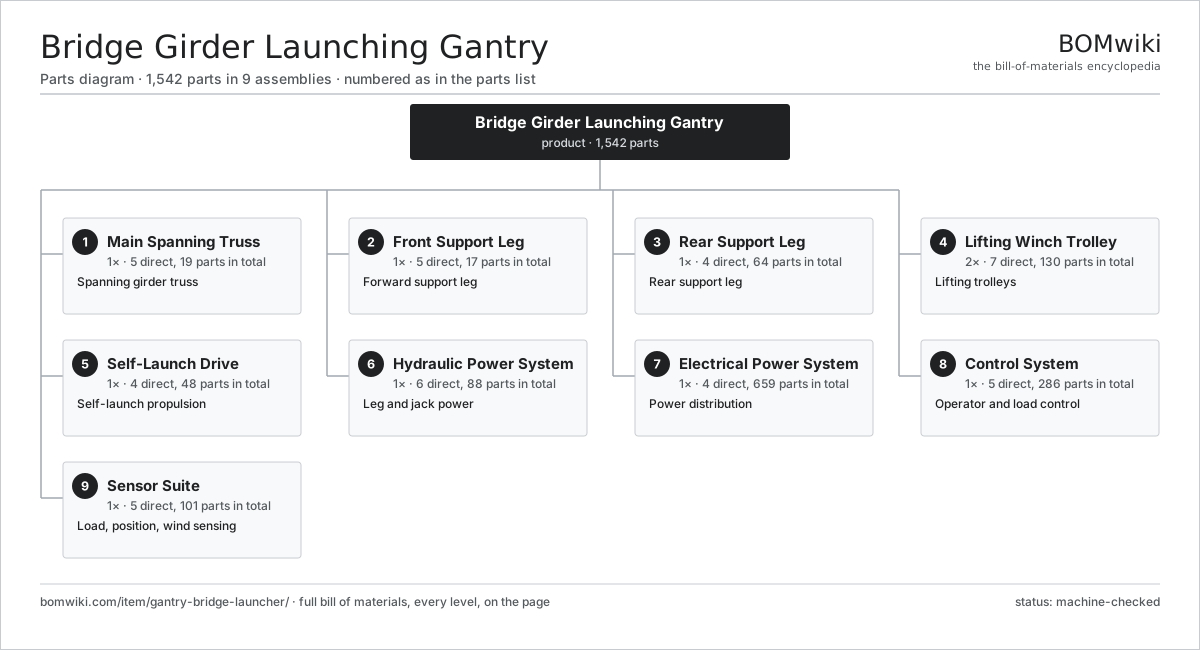
| # | Part | Qty | What it does |
|---|---|---|---|
| 1 | Main Spanning Truss 5 parts | 1× | Spanning girder truss |
| 2 | Front Support Leg 5 parts | 1× | Forward support leg |
| 3 | Rear Support Leg 4 parts | 1× | Rear support leg |
| 4 | Lifting Winch Trolley 7 parts | 2× | Lifting trolleys |
| 5 | Self-Launch Drive 4 parts | 1× | Self-launch propulsion |
| 6 | Hydraulic Power System 6 parts | 1× | Leg and jack power |
| 7 | Electrical Power System 4 parts | 1× | Power distribution |
| 8 | Control System 5 parts | 1× | Operator and load control |
| 9 | Sensor Suite 5 parts | 1× | Load, position, wind sensing |
3D model
No 3D model yet. Have a CAD file of this? Add a 3D model — STL renders right on this page; STEP, FreeCAD, and OpenSCAD sources are welcome too (openly licensed, like all 3D models on BOMwiki).
Build & assembly graph
expand / collapse · shared sub-assemblies converge · links to related products · est. labourTap an assembly to expand/collapse · tap a part to open it · use “Open page” for any node · drag to pan, scroll to zoom.
Bill of materials for Bridge Girder Launching Gantry
9 top-level lines · 125 rows shown · 1,542 parts total · indented to 3 levels| # | Item / sub-assembly | Part no. | Qty/assy | Ext. qty | Parts | Type |
|---|---|---|---|---|---|---|
| 1 | Main Spanning Truss 5 parts | gantry-bridge-launcher-main-truss | 1× | 1 | 19 | assembly |
| 1.1 | Truss Module | gantry-bridge-launcher-truss-module | 6× | 6 | · | part |
| 1.2 | Trolley Running Rail | gantry-bridge-launcher-top-rail | 2× | 2 | · | part |
| 1.3 | Splice Plate Set | gantry-bridge-launcher-splice-plate | 8× | 8 | · | part |
| 1.4 | Access Walkway | gantry-bridge-launcher-walkway | 2× | 2 | · | part |
| 1.5 | Fastener Set | fastener-set | 1× | 1 | · | part |
| 2 | Front Support Leg 5 parts | gantry-bridge-launcher-front-leg | 1× | 1 | 17 | assembly |
| 2.1 | Telescoping Leg Column | gantry-bridge-launcher-leg-column | 1× | 1 | · | part |
| 2.2 | Leveling Jack 4 parts | gantry-bridge-launcher-leg-jack | 2× | 2 | 5 | assembly |
| 2.2.1 | Cylinder Tube | gantry-bridge-launcher-cylinder-tube | 1× | 2 | · | part |
| 2.2.2 | Piston Rod | gantry-bridge-launcher-piston-rod | 1× | 2 | · | part |
| 2.2.3 | O-Ring Set | oring-set | 1× | 2 | · | part |
| 2.2.4 | Oil Seal | oil-seal | 2× | 4 | · | part |
| 2.3 | Pier Seat Bracket | gantry-bridge-launcher-pier-bracket | 1× | 1 | · | part |
| 2.4 | Leg Tilt Cylinder 3 parts | gantry-bridge-launcher-leg-cylinder | 1× | 1 | 3 | assembly |
| 2.4.1 | Cylinder Tube | gantry-bridge-launcher-cylinder-tube | 1× | 1 | · | part |
| 2.4.2 | Piston Rod | gantry-bridge-launcher-piston-rod | 1× | 1 | · | part |
| 2.4.3 | O-Ring Set | oring-set | 1× | 1 | · | part |
| 2.5 | Linear Guide Rail | linear-guide | 2× | 2 | · | part |
| 3 | Rear Support Leg 4 parts | gantry-bridge-launcher-rear-leg | 1× | 1 | 64 | assembly |
| 3.1 | Telescoping Leg Column | gantry-bridge-launcher-leg-column | 1× | 1 | · | part |
| 3.2 | Leveling Jack 4 parts | gantry-bridge-launcher-leg-jack | 2× | 2 | 5 | assembly |
| 3.2.1 | Cylinder Tube | gantry-bridge-launcher-cylinder-tube | 1× | 2 | · | part |
| 3.2.2 | Piston Rod | gantry-bridge-launcher-piston-rod | 1× | 2 | · | part |
| 3.2.3 | O-Ring Set | oring-set | 1× | 2 | · | part |
| 3.2.4 | Oil Seal | oil-seal | 2× | 4 | · | part |
| 3.3 | Rail Bogie 3 parts | gantry-bridge-launcher-bogie | 2× | 2 | 25 | assembly |
| 3.3.1 | Bogie Load Wheel | gantry-bridge-launcher-bogie-wheel | 8× | 16 | · | part |
| 3.3.2 | Ball Bearing | ball-bearing | 16× | 32 | · | part |
| 3.3.3 | Bogie Equalizer Frame | gantry-bridge-launcher-bogie-frame | 1× | 2 | · | part |
| 3.4 | Leg Tilt Cylinder 3 parts | gantry-bridge-launcher-leg-cylinder | 1× | 1 | 3 | assembly |
| 3.4.1 | Cylinder Tube | gantry-bridge-launcher-cylinder-tube | 1× | 1 | · | part |
| 3.4.2 | Piston Rod | gantry-bridge-launcher-piston-rod | 1× | 1 | · | part |
| 3.4.3 | O-Ring Set | oring-set | 1× | 1 | · | part |
| 4 | Lifting Winch Trolley 7 parts | gantry-bridge-launcher-winch-trolley | 2× | 2 | 130 | assembly |
| 4.1 | Hoist Winch 6 parts | gantry-bridge-launcher-winch | 1× | 2 | 70 | assembly |
| 4.1.1 | Winch Rope Drum | gantry-bridge-launcher-winch-drum | 1× | 2 | · | part |
| 4.1.2 | Planetary Reducer 4 parts + deeper › | gantry-bridge-launcher-gearbox | 1× | 2 | 10 | assembly |
| 4.1.3 | Servo Motor 4 parts + deeper › | servo-motor | 2× | 4 | 24 | assembly |
| 4.1.4 | Hoist Wire Rope | gantry-bridge-launcher-wire-rope | 1× | 2 | · | part |
| 4.1.5 | Hoist Holding Brake 3 parts + deeper › | gantry-bridge-launcher-brake | 1× | 2 | 6 | assembly |
| 4.1.6 | Ball Bearing | ball-bearing | 4× | 8 | · | part |
| 4.2 | Trolley Frame | gantry-bridge-launcher-trolley-frame | 1× | 2 | · | part |
| 4.3 | Trolley Rail Wheel | gantry-bridge-launcher-trolley-wheel | 4× | 8 | · | part |
| 4.4 | Trolley Traverse Drive 4 parts | gantry-bridge-launcher-traverse-drive | 1× | 2 | 37 | assembly |
| 4.4.1 | Servo Motor 4 parts + deeper › | servo-motor | 1× | 2 | 24 | assembly |
| 4.4.2 | Planetary Reducer 4 parts + deeper › | gantry-bridge-launcher-gearbox | 1× | 2 | 10 | assembly |
| 4.4.3 | Helical Gear Pair | gear-pair | 1× | 2 | · | part |
| 4.4.4 | Ball Bearing | ball-bearing | 2× | 4 | · | part |
| 4.5 | Girder Lifting Beam 3 parts | gantry-bridge-launcher-lifting-beam | 1× | 2 | 9 | assembly |
| 4.5.1 | Spreader Beam | gantry-bridge-launcher-spreader | 1× | 2 | · | part |
| 4.5.2 | Bow Shackle | gantry-bridge-launcher-shackle | 4× | 8 | · | part |
| 4.5.3 | Lifting Sling | gantry-bridge-launcher-sling | 4× | 8 | · | part |
| 4.6 | Ball Bearing | ball-bearing | 8× | 16 | · | part |
| 4.7 | Pressure Sensor | pressure-sensor | 1× | 2 | · | part |
| 5 | Self-Launch Drive 4 parts | gantry-bridge-launcher-launch-drive | 1× | 1 | 48 | assembly |
| 5.1 | Launch Winch 4 parts | gantry-bridge-launcher-launch-winch | 1× | 1 | 36 | assembly |
| 5.1.1 | Winch Rope Drum | gantry-bridge-launcher-winch-drum | 1× | 1 | · | part |
| 5.1.2 | Planetary Reducer 4 parts + deeper › | gantry-bridge-launcher-gearbox | 1× | 1 | 10 | assembly |
| 5.1.3 | Servo Motor 4 parts + deeper › | servo-motor | 1× | 1 | 24 | assembly |
| 5.1.4 | Hoist Wire Rope | gantry-bridge-launcher-wire-rope | 1× | 1 | · | part |
| 5.2 | Launch Drive Rack | gantry-bridge-launcher-launch-rack | 2× | 2 | · | part |
| 5.3 | Launch Push Cylinder 3 parts | gantry-bridge-launcher-launch-cylinder | 2× | 2 | 3 | assembly |
| 5.3.1 | Cylinder Tube | gantry-bridge-launcher-cylinder-tube | 1× | 2 | · | part |
| 5.3.2 | Piston Rod | gantry-bridge-launcher-piston-rod | 1× | 2 | · | part |
| 5.3.3 | O-Ring Set | oring-set | 1× | 2 | · | part |
| 5.4 | Hold-Down Clamp | gantry-bridge-launcher-clamp | 4× | 4 | · | part |
| 6 | Hydraulic Power System 6 parts | gantry-bridge-launcher-hydraulic-system | 1× | 1 | 88 | assembly |
| 6.1 | Hydraulic Pump 4 parts | gantry-bridge-launcher-hydraulic-pump | 2× | 2 | 28 | assembly |
| 6.1.1 | Pump Housing | gantry-bridge-launcher-pump-housing | 1× | 2 | · | part |
| 6.1.2 | Servo Motor 4 parts + deeper › | servo-motor | 1× | 2 | 24 | assembly |
| 6.1.3 | Ball Bearing | ball-bearing | 2× | 4 | · | part |
| 6.1.4 | Oil Seal | oil-seal | 1× | 2 | · | part |
| 6.2 | Valve Manifold Block 3 parts | gantry-bridge-launcher-valve-block | 1× | 1 | 26 | assembly |
| 6.2.1 | Solenoid Spool Valve | gantry-bridge-launcher-spool-valve | 10× | 10 | · | part |
| 6.2.2 | Counterbalance Valve | gantry-bridge-launcher-counterbalance-valve | 6× | 6 | · | part |
| 6.2.3 | Relay | relay | 10× | 10 | · | part |
| 6.3 | Hydraulic Reservoir | gantry-bridge-launcher-reservoir | 1× | 1 | · | part |
| 6.4 | Brake Accumulator | gantry-bridge-launcher-accumulator | 2× | 2 | · | part |
| 6.5 | Hose and Fitting Set | gantry-bridge-launcher-hose-set | 1× | 1 | · | part |
| 6.6 | O-Ring Set | oring-set | 2× | 2 | · | part |
| 7 | Electrical Power System 4 parts | gantry-bridge-launcher-electrical-system | 1× | 1 | 659 | assembly |
| 7.1 | Diesel Generator Set 3 parts | gantry-bridge-launcher-generator | 1× | 1 | 26 | assembly |
| 7.1.1 | Genset Diesel Engine | gantry-bridge-launcher-genset-engine | 1× | 1 | · | part |
| 7.1.2 | Generator Alternator 3 parts + deeper › | gantry-bridge-launcher-alternator | 1× | 1 | 24 | assembly |
| 7.1.3 | Fuel Tank | gantry-bridge-launcher-fuel-tank | 1× | 1 | · | part |
| 7.2 | Distribution Switchgear 3 parts | gantry-bridge-launcher-switchgear | 1× | 1 | 20 | assembly |
| 7.2.1 | Circuit Breaker | gantry-bridge-launcher-breaker | 6× | 6 | · | part |
| 7.2.2 | Relay | relay | 12× | 12 | · | part |
| 7.2.3 | Sheet Metal Panel | sheet-panel | 2× | 2 | · | part |
| 7.3 | Variable Frequency Drive 4 parts | gantry-bridge-launcher-vfd | 4× | 4 | 153 | assembly |
| 7.3.1 | Bare PCB | pcb-bare | 1× | 4 | · | part |
| 7.3.2 | Microcontroller | mcu | 1× | 4 | · | part |
| 7.3.3 | SMD Passive (R/C/L) | smd-passives | 150× | 600 | · | part |
| 7.3.4 | Power Supply | power-supply | 1× | 4 | · | part |
| 7.4 | Festoon Power Cable | gantry-bridge-launcher-power-cable | 1× | 1 | · | part |
| 8 | Control System 5 parts | gantry-bridge-launcher-control-system | 1× | 1 | 286 | assembly |
| 8.1 | PLC Module 4 parts | gantry-bridge-launcher-plc | 1× | 1 | 227 | assembly |
| 8.1.1 | Bare PCB | pcb-bare | 1× | 1 | · | part |
| 8.1.2 | Microcontroller | mcu | 2× | 2 | · | part |
| 8.1.3 | SMD Passive (R/C/L) | smd-passives | 200× | 200 | · | part |
| 8.1.4 | Connector | connector | 24× | 24 | · | part |
| 8.2 | Operator Console 4 parts | gantry-bridge-launcher-console | 1× | 1 | 12 | assembly |
| 8.2.1 | LCD Panel | lcd-panel | 2× | 2 | · | part |
| 8.2.2 | Bare PCB | pcb-bare | 1× | 1 | · | part |
| 8.2.3 | Microcontroller | mcu | 1× | 1 | · | part |
| 8.2.4 | Connector | connector | 8× | 8 | · | part |
| 8.3 | Radio Remote 4 parts | gantry-bridge-launcher-remote | 1× | 1 | 5 | assembly |
| 8.3.1 | LCD Panel | lcd-panel | 1× | 1 | · | part |
| 8.3.2 | Bare PCB | pcb-bare | 1× | 1 | · | part |
| 8.3.3 | Microcontroller | mcu | 1× | 1 | · | part |
| 8.3.4 | Connector | connector | 2× | 2 | · | part |
| 8.4 | Machine Wiring Harness 2 parts | gantry-bridge-launcher-wiring-harness | 1× | 1 | 41 | assembly |
| 8.4.1 | Wire Bundle | wire-bundle | 1× | 1 | · | part |
| 8.4.2 | Connector | connector | 40× | 40 | · | part |
| 8.5 | Power Supply | power-supply | 1× | 1 | · | part |
| 9 | Sensor Suite 5 parts | gantry-bridge-launcher-sensor-suite | 1× | 1 | 101 | assembly |
| 9.1 | Hoist Load Cell 3 parts | gantry-bridge-launcher-load-cell | 4× | 4 | 22 | assembly |
| 9.1.1 | Bare PCB | pcb-bare | 1× | 4 | · | part |
| 9.1.2 | SMD Passive (R/C/L) | smd-passives | 20× | 80 | · | part |
| 9.1.3 | Connector | connector | 1× | 4 | · | part |
| 9.2 | Position Encoder | gantry-bridge-launcher-position-encoder | 4× | 4 | · | part |
| 9.3 | Inclinometer | gantry-bridge-launcher-inclinometer | 4× | 4 | · | part |
| 9.4 | Anemometer | gantry-bridge-launcher-anemometer | 1× | 1 | · | part |
| 9.5 | Pressure Sensor | pressure-sensor | 4× | 4 | · | part |
Related products
same domain, ranked by shared parts Tracked Asphalt Paver
1,299 parts · shares 25 with this page
Rebar Shearing and Bending Line
361 parts · shares 23 with this page
Tracked Asphalt Paver
1,299 parts · shares 25 with this page
Rebar Shearing and Bending Line
361 parts · shares 23 with this page
 Guardrail Installation Rig
320 parts · shares 24 with this page
Guardrail Installation Rig
320 parts · shares 24 with this page
 Rebar Cage Welding Machine
1,702 parts · shares 24 with this page
Sheet Pile Press
403 parts · shares 22 with this page
Rebar Cage Welding Machine
1,702 parts · shares 24 with this page
Sheet Pile Press
403 parts · shares 22 with this page
 Tandem Vibratory Roller
369 parts · shares 24 with this page
Tandem Vibratory Roller
369 parts · shares 24 with this page
Sourcing: possible vendors
Prices, MOQ, and lead times are algorithmic estimates, not quotes, and not claims about these companies. Company mappings are curated by keyword; est. price band $15k–$2M. How estimates work| Vendor | HQ | Specialty | MOQ | Lead time |
|---|---|---|---|---|
| caterpillar.com ↗ | Irving, US | Construction & mining equipment | made to order | 16–28 wks |
|
🇯🇵Komatsu
komatsu.com ↗
|
Tokyo, JP | Construction & mining equipment | made to order | 16–28 wks |
|
🇸🇪Volvo CE
volvoce.com ↗
|
Gothenburg, SE | Construction equipment | made to order | 16–28 wks |
|
🇨🇭Liebherr
liebherr.com ↗
|
Bulle, CH | Cranes & heavy equipment | made to order | 16–28 wks |
|
🇨🇳XCMG
xcmg.com ↗
|
Xuzhou, CN | Construction machinery | made to order | 16–28 wks |
1,010-word article