Pipelayer
ProductOverview
A pipelayer is a tracked tractor fitted with a boom that lifts to the side rather than to the front. It is built to carry, lower, and hold large-diameter pipe while a welded pipeline string is laid into an open trench. The crew runs pipelayers in a line, called a spread, so that several machines share the weight of a long section of joined pipe as it is moved and set down. The machine combines the traction and low ground pressure of a crawler tractor with a lifting frame that can hold heavy loads steady on uneven right-of-way.
The pipelayer is built around a heavy welded Main Frame. A diesel Diesel Engine drives the Powertrain to the tracks and supplies the hydraulics that turn the winches. The Side Boom Assembly pivots off the left side of the frame, and a Counterweight System swings out on the right side to balance the load. The operator works from a Operator Cab set high enough to watch both the load and the trench.
Engine and powertrain
The power unit is a turbocharged six-cylinder diesel that meets Stage V and Tier 4 Final limits. Air passes through a two-stage Air Cleaner Housing, is compressed by the Turbocharger, and is cooled again by the Charge Air Cooler before reaching the cylinders. A common-rail Fuel Injection System system meters fuel near 2000 bar for clean combustion at low engine speeds, which is where a pipelayer spends most of its time. The Aftertreatment Module module traps soot in the Diesel Particulate Filter and converts nitrogen oxides in the SCR Catalyst.
Travel power flows from a Torque Converter through a powershift Transmission to a Final Drive on each side, where a double-reduction Planetary Gear Set multiplies torque just before the Drive Sprocket. The machine is geared for slow, controlled travel because it carries its load while moving, often at a walking pace, with the rest of the spread matching speed. A Steering Clutch on each side slows one track to steer.
Undercarriage
The undercarriage is wider and heavier than the dozer it derives from, because the side load tries to roll the machine over the loaded track. The Track Chain is a sealed and lubricated loop of Track Link pieces joined by Track Pin and Track Bushing parts. Wide Track Shoe (Grouser) grousers spread the weight so the machine does not sink into soft trench spoil. The chain runs on a row of Track Roller units and wraps the Front Idler, all carried on the welded Track Frame and tensioned by the Track Adjuster. A wide track gauge increases the distance from the machine center of gravity to the tipping edge, which is what lets a pipelayer hold a heavy load out to the side.
Side boom and winches
The lifting frame is the part that sets a pipelayer apart. The Side Boom Assembly is a Boom Structure of welded box section or tubular lattice, pinned to the Boom Mount by a Boom Foot Pin pair so it can be raised and lowered. Two wire ropes run up the boom. The boom hoist line from the Boom Winch runs over the Boom Line Sheave Block and sets the boom angle. The load hoist line from the Load Winch runs over the Load Line Sheave Block, down through the Hook Block, and back up, so the Load Hoist Wire Rope is reeved through several Wire Rope Sheave grooves to multiply the line pull and reduce the rope tension at any one part.
Each winch is a grooved Winch Drum turned by a hydraulic Winch Drive Motor through a planetary Winch Reduction Gearbox. A spring-applied Winch Holding Brake holds the drum whenever the operator is not actively paying rope in or out, so a suspended pipe cannot drift down on its own. The Boom Hoist Wire Rope and load rope are inspected against EN 12385 limits for broken wires and wear, because a pipelayer holds graded pipe over an open trench where a dropped load is dangerous and expensive.
Counterweight and stability
A pipelayer lifts off one side, so without a counterweight it would tip onto the loaded track. The Counterweight System solves this with a Counterweight Block carried on a Counterweight Arm that pivots and extends. As the load and boom radius grow, the operator pays out the Counterweight Cylinder to swing the counterweight farther out on the opposite side, increasing its lever arm to balance the load moment. This is the heart of how the machine works. The load tries to turn the tractor about the tipping line of the loaded track, and the counterweight produces an opposing moment about the same line. The Load Moment Indicator in the cab reads boom cylinder pressure and boom angle, computes the load and radius, and warns the operator before the lift approaches the rated tipping limit. Capacity is highest at minimum radius and falls off as the load is held farther from the machine, so a pipelayer is rated by a load chart rather than a single number.
Controls, cab, and electrical
The operator runs the boom winch, load winch, counterweight, and travel from a Control Lever set in the Operator Cab. The cab is a Cab Frame (ROPS) rollover structure with a suspension Operator Seat and clear sightlines down to the trench and up to the hook. The Hydraulic System supplies the winch motors and cylinders through a Main Control Valve bank whose Counterbalance Valve sections hold the load steady against gravity. A load-sensing Main Hydraulic Pump delivers only the flow demanded. The 24 V Electrical System ties the machine together, with the Engine and Machine Controller running the engine and reading the load monitor sensors.
Operation in pipeline spreads
On a job, pipelayers work in groups along the right-of-way. Several machines lift a welded string at once, each holding its share of the weight on slings hung from the Hook Block, and they travel together to lower the string into the trench. Coordinated travel speed keeps the bending stress in the pipe within limits, since the string flexes between machines as it is carried. Variants include lattice-boom models for the heaviest large-diameter line pipe and compact box-boom models for smaller distribution work and tie-ins. Hydrostatic and load-sensing hydraulics on newer machines give finer winch control than the older mechanical pipelayers, which matters when a crew is setting a coated pipe joint into place without damaging the coating.
Pipelayer parts and their functions
10 top-level parts · 1,219 parts in total · full bill of materials below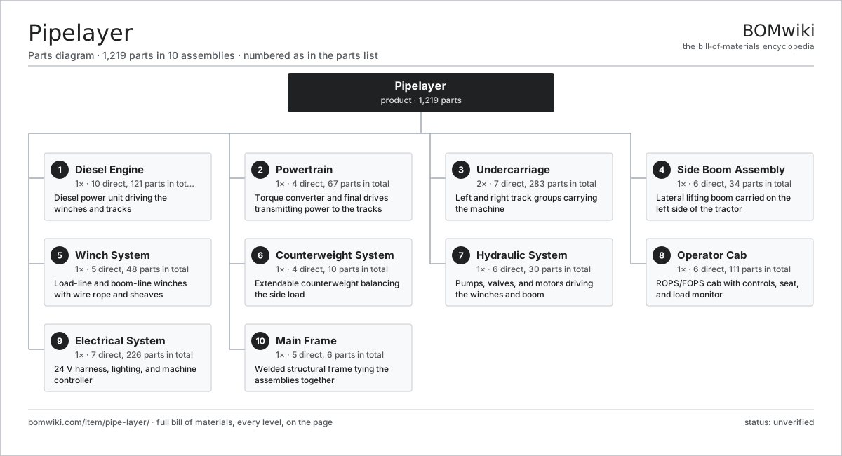
| # | Part | Qty | What it does |
|---|---|---|---|
| 1 | Diesel Engine 10 parts | 1× | Diesel power unit driving the winches and tracks |
| 2 | Powertrain 4 parts | 1× | Torque converter and final drives transmitting power to the tracks |
| 3 | Undercarriage 7 parts | 2× | Left and right track groups carrying the machine |
| 4 | Side Boom Assembly 6 parts | 1× | Lateral lifting boom carried on the left side of the tractor |
| 5 | Winch System 5 parts | 1× | Load-line and boom-line winches with wire rope and sheaves |
| 6 | Counterweight System 4 parts | 1× | Extendable counterweight balancing the side load |
| 7 | Hydraulic System 6 parts | 1× | Pumps, valves, and motors driving the winches and boom |
| 8 | Operator Cab 6 parts | 1× | ROPS/FOPS cab with controls, seat, and load monitor |
| 9 | Electrical System 7 parts | 1× | 24 V harness, lighting, and machine controller |
| 10 | Main Frame 5 parts | 1× | Welded structural frame tying the assemblies together |
3D model
No 3D model yet. Have a CAD file of this? Add a 3D model — STL renders right on this page; STEP, FreeCAD, and OpenSCAD sources are welcome too (openly licensed, like all 3D models on BOMwiki).
Build & assembly graph
expand / collapse · shared sub-assemblies converge · links to related products · est. labourTap an assembly to expand/collapse · tap a part to open it · use “Open page” for any node · drag to pan, scroll to zoom.
Bill of materials for Pipelayer
10 top-level lines · 171 rows shown · 1,219 parts total · indented to 3 levels| # | Item / sub-assembly | Part no. | Qty/assy | Ext. qty | Parts | Type |
|---|---|---|---|---|---|---|
| 1 | Diesel Engine 10 parts | pipe-layer-engine | 1× | 1 | 121 | assembly |
| 1.1 | Cylinder Block | pipe-layer-cylinder-block | 1× | 1 | · | part |
| 1.2 | Cylinder Head 4 parts | pipe-layer-cylinder-head | 1× | 1 | 50 | assembly |
| 1.2.1 | Engine Valve | pipe-layer-valve-set | 24× | 24 | · | part |
| 1.2.2 | Coil Spring | coil-spring | 24× | 24 | · | part |
| 1.2.3 | Rocker Shaft Assembly | pipe-layer-rocker-shaft | 1× | 1 | · | part |
| 1.2.4 | O-Ring Set | oring-set | 1× | 1 | · | part |
| 1.3 | Crankshaft | pipe-layer-crankshaft | 1× | 1 | · | part |
| 1.4 | Piston and Rod Set 4 parts | pipe-layer-piston-set | 6× | 6 | 6 | assembly |
| 1.4.1 | Piston | pipe-layer-piston | 1× | 6 | · | part |
| 1.4.2 | Piston Ring | pipe-layer-piston-ring | 3× | 18 | · | part |
| 1.4.3 | Connecting Rod | pipe-layer-conrod | 1× | 6 | · | part |
| 1.4.4 | Ball Bearing | ball-bearing | 1× | 6 | · | part |
| 1.5 | Turbocharger 5 parts | pipe-layer-turbocharger | 1× | 1 | 6 | assembly |
| 1.5.1 | Turbine Housing | pipe-layer-turbo-housing | 1× | 1 | · | part |
| 1.5.2 | Turbine Wheel | pipe-layer-turbine-wheel | 1× | 1 | · | part |
| 1.5.3 | Compressor Wheel | pipe-layer-compressor-wheel | 1× | 1 | · | part |
| 1.5.4 | Ball Bearing | ball-bearing | 2× | 2 | · | part |
| 1.5.5 | Wastegate Actuator | pipe-layer-wastegate | 1× | 1 | · | part |
| 1.6 | Fuel Injection System 5 parts | pipe-layer-fuel-injection | 1× | 1 | 11 | assembly |
| 1.6.1 | High-Pressure Pump | pipe-layer-injection-pump | 1× | 1 | · | part |
| 1.6.2 | Common Rail | pipe-layer-common-rail | 1× | 1 | · | part |
| 1.6.3 | Fuel Injector | pipe-layer-injector | 6× | 6 | · | part |
| 1.6.4 | Fuel Filter | pipe-layer-fuel-filter | 2× | 2 | · | part |
| 1.6.5 | Pressure Sensor | pressure-sensor | 1× | 1 | · | part |
| 1.7 | Cooling Package 5 parts | pipe-layer-cooling-package | 1× | 1 | 5 | assembly |
| 1.7.1 | Radiator Core | pipe-layer-radiator | 1× | 1 | · | part |
| 1.7.2 | Charge Air Cooler | pipe-layer-charge-air-cooler | 1× | 1 | · | part |
| 1.7.3 | Cooling Fan | pipe-layer-fan | 1× | 1 | · | part |
| 1.7.4 | Fan Drive Motor | pipe-layer-fan-motor | 1× | 1 | · | part |
| 1.7.5 | Coolant Pump | pipe-layer-coolant-pump | 1× | 1 | · | part |
| 1.8 | Aftertreatment Module 4 parts | pipe-layer-aftertreatment | 1× | 1 | 5 | assembly |
| 1.8.1 | Diesel Particulate Filter | pipe-layer-dpf | 1× | 1 | · | part |
| 1.8.2 | SCR Catalyst | pipe-layer-scr-catalyst | 1× | 1 | · | part |
| 1.8.3 | DEF Dosing Injector | pipe-layer-def-injector | 1× | 1 | · | part |
| 1.8.4 | NOx Sensor | pipe-layer-nox-sensor | 2× | 2 | · | part |
| 1.9 | Air Intake System 3 parts | pipe-layer-air-intake | 1× | 1 | 4 | assembly |
| 1.9.1 | Air Cleaner Housing | pipe-layer-air-cleaner | 1× | 1 | · | part |
| 1.9.2 | Air Filter Element | pipe-layer-air-element | 2× | 2 | · | part |
| 1.9.3 | Intake Duct | pipe-layer-intake-duct | 1× | 1 | · | part |
| 1.10 | Oil Seal | oil-seal | 2× | 2 | · | part |
| 2 | Powertrain 4 parts | pipe-layer-powertrain | 1× | 1 | 67 | assembly |
| 2.1 | Torque Converter 4 parts | pipe-layer-torque-converter | 1× | 1 | 5 | assembly |
| 2.1.1 | Converter Impeller | pipe-layer-impeller | 1× | 1 | · | part |
| 2.1.2 | Converter Turbine | pipe-layer-turbine | 1× | 1 | · | part |
| 2.1.3 | Converter Stator | pipe-layer-stator | 1× | 1 | · | part |
| 2.1.4 | Oil Seal | oil-seal | 2× | 2 | · | part |
| 2.2 | Transmission 5 parts | pipe-layer-transmission | 1× | 1 | 20 | assembly |
| 2.2.1 | Helical Gear Pair | gear-pair | 3× | 3 | · | part |
| 2.2.2 | Gearbox Housing | gearbox-housing | 1× | 1 | · | part |
| 2.2.3 | Clutch Pack | pipe-layer-clutch-pack | 4× | 4 | · | part |
| 2.2.4 | Ball Bearing | ball-bearing | 8× | 8 | · | part |
| 2.2.5 | Oil Seal | oil-seal | 4× | 4 | · | part |
| 2.3 | Final Drive 5 parts | pipe-layer-final-drive | 2× | 2 | 20 | assembly |
| 2.3.1 | Planetary Gear Set 4 parts + deeper › | pipe-layer-planetary-set | 2× | 4 | 6 | assembly |
| 2.3.2 | Gearbox Housing | gearbox-housing | 1× | 2 | · | part |
| 2.3.3 | Ball Bearing | ball-bearing | 4× | 8 | · | part |
| 2.3.4 | Oil Seal | oil-seal | 2× | 4 | · | part |
| 2.3.5 | Drive Sprocket | pipe-layer-sprocket | 1× | 2 | · | part |
| 2.4 | Steering Clutch | pipe-layer-steering-clutch | 2× | 2 | · | part |
| 3 | Undercarriage 7 parts | pipe-layer-undercarriage | 2× | 2 | 283 | assembly |
| 3.1 | Track Chain 4 parts | pipe-layer-track-chain | 1× | 2 | 225 | assembly |
| 3.1.1 | Track Link | pipe-layer-track-link | 90× | 180 | · | part |
| 3.1.2 | Track Pin | pipe-layer-track-pin | 45× | 90 | · | part |
| 3.1.3 | Track Bushing | pipe-layer-track-bushing | 45× | 90 | · | part |
| 3.1.4 | Oil Seal | oil-seal | 45× | 90 | · | part |
| 3.2 | Track Shoe (Grouser) | pipe-layer-track-shoe | 45× | 90 | · | part |
| 3.3 | Track Roller | pipe-layer-track-roller | 8× | 16 | · | part |
| 3.4 | Carrier Roller | pipe-layer-carrier-roller | 2× | 4 | · | part |
| 3.5 | Front Idler | pipe-layer-front-idler | 1× | 2 | · | part |
| 3.6 | Track Adjuster | pipe-layer-track-adjuster | 1× | 2 | · | part |
| 3.7 | Track Frame | pipe-layer-track-frame | 1× | 2 | · | part |
| 4 | Side Boom Assembly 6 parts | pipe-layer-side-boom | 1× | 1 | 34 | assembly |
| 4.1 | Boom Structure 3 parts | pipe-layer-boom-structure | 1× | 1 | 4 | assembly |
| 4.1.1 | Boom Section | pipe-layer-boom-section | 2× | 2 | · | part |
| 4.1.2 | Boom Joint Pin Set | pipe-layer-boom-pin-set | 1× | 1 | · | part |
| 4.1.3 | Fastener Set | fastener-set | 1× | 1 | · | part |
| 4.2 | Boom Foot Pin | pipe-layer-boom-foot-pin | 2× | 2 | · | part |
| 4.3 | Load Line Sheave Block 3 parts | pipe-layer-load-sheave | 1× | 1 | 10 | assembly |
| 4.3.1 | Wire Rope Sheave | pipe-layer-sheave | 3× | 3 | · | part |
| 4.3.2 | Ball Bearing | ball-bearing | 6× | 6 | · | part |
| 4.3.3 | Sheave Axle Pin | pipe-layer-sheave-pin | 1× | 1 | · | part |
| 4.4 | Boom Line Sheave Block 3 parts | pipe-layer-boom-sheave | 1× | 1 | 10 | assembly |
| 4.4.1 | Wire Rope Sheave | pipe-layer-sheave | 3× | 3 | · | part |
| 4.4.2 | Ball Bearing | ball-bearing | 6× | 6 | · | part |
| 4.4.3 | Sheave Axle Pin | pipe-layer-sheave-pin | 1× | 1 | · | part |
| 4.5 | Hook Block 4 parts | pipe-layer-hook-block | 1× | 1 | 7 | assembly |
| 4.5.1 | Wire Rope Sheave | pipe-layer-sheave | 3× | 3 | · | part |
| 4.5.2 | Lifting Hook | pipe-layer-hook | 1× | 1 | · | part |
| 4.5.3 | Ball Bearing | ball-bearing | 2× | 2 | · | part |
| 4.5.4 | Block Side Plate | pipe-layer-block-shell | 1× | 1 | · | part |
| 4.6 | Boom Rest Cradle | pipe-layer-boom-rest | 1× | 1 | · | part |
| 5 | Winch System 5 parts | pipe-layer-winch-system | 1× | 1 | 48 | assembly |
| 5.1 | Load Winch 6 parts | pipe-layer-load-winch | 1× | 1 | 22 | assembly |
| 5.1.1 | Winch Drum | pipe-layer-winch-drum | 1× | 1 | · | part |
| 5.1.2 | Winch Drive Motor | pipe-layer-winch-motor | 1× | 1 | · | part |
| 5.1.3 | Winch Reduction Gearbox 4 parts + deeper › | pipe-layer-winch-gearbox | 1× | 1 | 13 | assembly |
| 5.1.4 | Helical Gear Pair | gear-pair | 1× | 1 | · | part |
| 5.1.5 | Ball Bearing | ball-bearing | 4× | 4 | · | part |
| 5.1.6 | Oil Seal | oil-seal | 2× | 2 | · | part |
| 5.2 | Boom Winch 6 parts | pipe-layer-boom-winch | 1× | 1 | 22 | assembly |
| 5.2.1 | Winch Drum | pipe-layer-winch-drum | 1× | 1 | · | part |
| 5.2.2 | Winch Drive Motor | pipe-layer-winch-motor | 1× | 1 | · | part |
| 5.2.3 | Winch Reduction Gearbox 4 parts + deeper › | pipe-layer-winch-gearbox | 1× | 1 | 13 | assembly |
| 5.2.4 | Helical Gear Pair | gear-pair | 1× | 1 | · | part |
| 5.2.5 | Ball Bearing | ball-bearing | 4× | 4 | · | part |
| 5.2.6 | Oil Seal | oil-seal | 2× | 2 | · | part |
| 5.3 | Load Hoist Wire Rope | pipe-layer-load-rope | 1× | 1 | · | part |
| 5.4 | Boom Hoist Wire Rope | pipe-layer-boom-rope | 1× | 1 | · | part |
| 5.5 | Winch Holding Brake | pipe-layer-winch-brake | 2× | 2 | · | part |
| 6 | Counterweight System 4 parts | pipe-layer-counterweight-system | 1× | 1 | 10 | assembly |
| 6.1 | Counterweight Block | pipe-layer-counterweight-block | 1× | 1 | · | part |
| 6.2 | Counterweight Arm | pipe-layer-cw-arm | 1× | 1 | · | part |
| 6.3 | Counterweight Cylinder 5 parts | pipe-layer-cw-cylinder | 1× | 1 | 6 | assembly |
| 6.3.1 | Cylinder Barrel | pipe-layer-cyl-barrel | 1× | 1 | · | part |
| 6.3.2 | Cylinder Rod | pipe-layer-cyl-rod | 1× | 1 | · | part |
| 6.3.3 | Cylinder Piston | pipe-layer-cyl-piston | 1× | 1 | · | part |
| 6.3.4 | O-Ring Set | oring-set | 1× | 1 | · | part |
| 6.3.5 | Oil Seal | oil-seal | 2× | 2 | · | part |
| 6.4 | Counterweight Pivot Pin | pipe-layer-cw-pivot-pin | 2× | 2 | · | part |
| 7 | Hydraulic System 6 parts | pipe-layer-hydraulic-system | 1× | 1 | 30 | assembly |
| 7.1 | Main Hydraulic Pump | pipe-layer-main-pump | 1× | 1 | · | part |
| 7.2 | Main Control Valve 5 parts | pipe-layer-control-valve | 1× | 1 | 11 | assembly |
| 7.2.1 | Valve Spool | pipe-layer-valve-spool | 4× | 4 | · | part |
| 7.2.2 | Relief Valve | pipe-layer-relief-valve | 2× | 2 | · | part |
| 7.2.3 | Counterbalance Valve | pipe-layer-counterbalance-valve | 2× | 2 | · | part |
| 7.2.4 | O-Ring Set | oring-set | 2× | 2 | · | part |
| 7.2.5 | Valve Body | pipe-layer-valve-body | 1× | 1 | · | part |
| 7.3 | Hydraulic Tank | pipe-layer-hydraulic-tank | 1× | 1 | · | part |
| 7.4 | Hydraulic Oil Cooler | pipe-layer-hydraulic-cooler | 1× | 1 | · | part |
| 7.5 | Hydraulic Hose | pipe-layer-hydraulic-hose | 14× | 14 | · | part |
| 7.6 | Pressure Sensor | pressure-sensor | 2× | 2 | · | part |
| 8 | Operator Cab 6 parts | pipe-layer-operator-cab | 1× | 1 | 111 | assembly |
| 8.1 | Cab Frame (ROPS) | pipe-layer-cab-frame | 1× | 1 | · | part |
| 8.2 | Cab Glass | pipe-layer-cab-glass | 4× | 4 | · | part |
| 8.3 | Operator Seat | pipe-layer-seat | 1× | 1 | · | part |
| 8.4 | Control Lever 4 parts | pipe-layer-control-lever | 3× | 3 | 5 | assembly |
| 8.4.1 | Lever Grip | pipe-layer-lever-grip | 1× | 3 | · | part |
| 8.4.2 | Hall Position Sensor | pipe-layer-hall-sensor | 2× | 6 | · | part |
| 8.4.3 | Bare PCB | pcb-bare | 1× | 3 | · | part |
| 8.4.4 | Connector | connector | 1× | 3 | · | part |
| 8.5 | Load Moment Indicator 6 parts | pipe-layer-load-monitor | 1× | 1 | 86 | assembly |
| 8.5.1 | LCD Panel | lcd-panel | 1× | 1 | · | part |
| 8.5.2 | Bare PCB | pcb-bare | 1× | 1 | · | part |
| 8.5.3 | Microcontroller | mcu | 1× | 1 | · | part |
| 8.5.4 | SMD Passive (R/C/L) | smd-passives | 80× | 80 | · | part |
| 8.5.5 | Connector | connector | 2× | 2 | · | part |
| 8.5.6 | Pressure Sensor | pressure-sensor | 1× | 1 | · | part |
| 8.6 | Cab HVAC Unit 4 parts | pipe-layer-hvac | 1× | 1 | 4 | assembly |
| 8.6.1 | Heating Element | heating-element | 1× | 1 | · | part |
| 8.6.2 | Cab Blower | pipe-layer-blower | 1× | 1 | · | part |
| 8.6.3 | AC Compressor | pipe-layer-ac-compressor | 1× | 1 | · | part |
| 8.6.4 | Cabin Air Filter | pipe-layer-cabin-filter | 1× | 1 | · | part |
| 9 | Electrical System 7 parts | pipe-layer-electrical-system | 1× | 1 | 226 | assembly |
| 9.1 | Battery | pipe-layer-battery | 2× | 2 | · | part |
| 9.2 | Alternator | pipe-layer-alternator | 1× | 1 | · | part |
| 9.3 | Starter Motor | pipe-layer-starter | 1× | 1 | · | part |
| 9.4 | Engine and Machine Controller 4 parts | pipe-layer-ecm | 1× | 1 | 207 | assembly |
| 9.4.1 | Bare PCB | pcb-bare | 1× | 1 | · | part |
| 9.4.2 | Microcontroller | mcu | 2× | 2 | · | part |
| 9.4.3 | SMD Passive (R/C/L) | smd-passives | 200× | 200 | · | part |
| 9.4.4 | Connector | connector | 4× | 4 | · | part |
| 9.5 | Wire Bundle | wire-bundle | 1× | 1 | · | part |
| 9.6 | LED Work Light | pipe-layer-work-light | 6× | 6 | · | part |
| 9.7 | Relay | relay | 8× | 8 | · | part |
| 10 | Main Frame 5 parts | pipe-layer-mainframe | 1× | 1 | 6 | assembly |
| 10.1 | Frame Weldment | pipe-layer-frame-weldment | 1× | 1 | · | part |
| 10.2 | Boom Mount | pipe-layer-boom-mount | 1× | 1 | · | part |
| 10.3 | Counterweight Mount | pipe-layer-cw-mount | 1× | 1 | · | part |
| 10.4 | Pivot Shaft | pipe-layer-pivot-shaft | 2× | 2 | · | part |
| 10.5 | Fastener Set | fastener-set | 1× | 1 | · | part |
Related products
same domain, ranked by shared parts Crawler Dozer
1,111 parts · shares 12 with this page
Crawler Dozer
1,111 parts · shares 12 with this page
 Crawler Excavator
1,241 parts · shares 12 with this page
Crawler Excavator
1,241 parts · shares 12 with this page
 Crawler Tractor
1,361 parts · shares 12 with this page
Crawler Tractor
1,361 parts · shares 12 with this page
 Ring-Mounted Heavy Crane
2,831 parts · shares 12 with this page
Ring-Mounted Heavy Crane
2,831 parts · shares 12 with this page
 Tracked Asphalt Paver
1,299 parts · shares 12 with this page
Tracked Asphalt Paver
1,299 parts · shares 12 with this page
 Wheeled Excavator
772 parts · shares 12 with this page
Wheeled Excavator
772 parts · shares 12 with this page
Sourcing: possible vendors
Prices, MOQ, and lead times are algorithmic estimates, not quotes, and not claims about these companies. Company mappings are curated by keyword; est. price band $15k–$2M. How estimates work| Vendor | HQ | Specialty | MOQ | Lead time |
|---|---|---|---|---|
| caterpillar.com ↗ | Irving, US | Construction & mining equipment | made to order | 16–28 wks |
|
🇯🇵Komatsu
komatsu.com ↗
|
Tokyo, JP | Construction & mining equipment | made to order | 16–28 wks |
|
🇸🇪Volvo CE
volvoce.com ↗
|
Gothenburg, SE | Construction equipment | made to order | 16–28 wks |
|
🇨🇭Liebherr
liebherr.com ↗
|
Bulle, CH | Cranes & heavy equipment | made to order | 16–28 wks |
|
🇨🇳XCMG
xcmg.com ↗
|
Xuzhou, CN | Construction machinery | made to order | 16–28 wks |
1,173-word article