Grout Pump
ProductOverview
A grout pump is a positive-displacement piston pump mounted on a self-contained skid with a Mixer Tank Assembly, a hydraulic drive, hose reel, and controls. It meters flowable grout from the tank into a delivery hose under pressure, typically 20–80 bar depending on grout viscosity and line distance. The operator controls discharge pressure and flow rate, adjusting for soil conditions, hole depth, and viscosity changes as grout sets.
The pump is essential for deep foundation anchoring, dam grouting, and soil stabilization where controlled placement and pressure are critical. Unlike concrete pumps that push large volumes, grout pumps are designed for precision at lower flow rates over long distances, often hundreds of metres vertically or horizontally.
How it works
The Diesel Engine, a compact turbodiesel, idles on the skid and drives a main hydraulic pump that supplies pressurized oil to the Hydraulic Motor. This motor, through a crankshaft linkage, reciprocates the Piston Rod in the pump Pump Casting at rates of 20–60 cycles per minute.
On the intake stroke, the piston draws grout from the Pump Suction Port submerged in the Mixer Tank Assembly. The Check Valve intake check opens to admit grout. On the discharge stroke, the piston pushes grout forward, the intake check slams shut, and the discharge check opens to force grout through the Pressure Hose to the Hose Reel Assembly and out into the borehole or grout line.
The Mixer Tank Assembly continuously stirs the grout slurry with the Mixer Paddle & Drive paddle, preventing coarse particles from settling and clogging the pump. The paddle shaft turns at 20–60 rpm, gently folding the material. If grout sits too long without mixing, it can set and lock the pump solid, so the agitator runs continuously during and between pumping intervals.
Pressure control is handled by the Relief Valve, an adjustable relief that vents excess flow back to tank once the pressure limit is reached. The operator adjusts this limit via a lever or screw, watching the Pressure Gauge and Flow Meter to match grout viscosity and delivery conditions. Thicker grout requires higher pressure; runny pre-grouted sand requires lower pressure to avoid breaking the hole wall.
The Hose Reel Assembly stores 100–500 metres of reinforced hose. Some reels are powered to auto-feed hose; most are hand-cranked or allowed to unwind as grout flows. The discharge hose ends in a Hose Guide & Swivel, a swivel union that allows the hose to rotate freely without twisting the reel or tangling.
All hydraulic circuits feed from the engine-driven main pump in the Hydraulic Drive System, a simple circuit with minimal filtration, grout is abrasive and clogs fine mesh, so coarse strainers are common. The system is rugged and slow; a piston pump running at 1,500 rpm is gentle enough not to foam or degrade the grout.
Grout Pump parts and their functions
8 top-level parts · 53 parts in total · full bill of materials below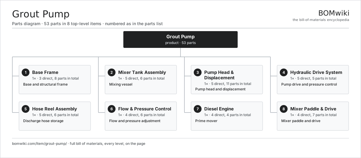
| # | Part | Qty | What it does |
|---|---|---|---|
| 1 | Base Frame 3 parts | 1× | Base and structural frame |
| 2 | Mixer Tank Assembly 5 parts | 1× | Mixing vessel |
| 3 | Pump Head & Displacement 5 parts | 1× | Pump head and displacement |
| 4 | Hydraulic Drive System 5 parts | 1× | Pump drive and pressure control |
| 5 | Hose Reel Assembly 5 parts | 1× | Discharge hose storage |
| 6 | Flow & Pressure Control 4 parts | 1× | Flow and pressure adjustment |
| 7 | Diesel Engine 4 parts | 1× | Prime mover |
| 8 | Mixer Paddle & Drive 4 parts | 1× | Mixer paddle and drive |
3D model
No 3D model yet. Have a CAD file of this? Add a 3D model. STL renders right on this page; STEP, FreeCAD, and OpenSCAD sources are welcome too (openly licensed, like all 3D models on BOMwiki).
Build & assembly graph
expand / collapse · shared sub-assemblies converge · links to related products · est. labourTap an assembly to expand/collapse · tap a part to open it · use “Open page” for any node · drag to pan, scroll to zoom.
Bill of materials for Grout Pump
8 top-level lines · 43 rows shown · 53 parts total · indented to 3 levels| # | Item / sub-assembly | Part no. | Qty/assy | Ext. qty | Parts | Type |
|---|---|---|---|---|---|---|
| 1 | Base Frame 3 parts | grout-pump-frame | 1× | 1 | 8 | assembly |
| 1.1 | Main Frame Structure | grout-pump-main-frame | 1× | 1 | · | part |
| 1.2 | Rubber Isolation Foot | grout-pump-skid-feet | 4× | 4 | · | part |
| 1.3 | Fastener Set | fastener-set | 3× | 3 | · | part |
| 2 | Mixer Tank Assembly 5 parts | grout-pump-mixer-tank | 1× | 1 | 6 | assembly |
| 2.1 | Tank Vessel | grout-pump-tank-shell | 1× | 1 | · | part |
| 2.2 | Tank Baffles | grout-pump-tank-baffles | 1× | 1 | · | part |
| 2.3 | Inlet Port | grout-pump-inlet-port | 1× | 1 | · | part |
| 2.4 | Pump Suction Port | grout-pump-outlet-port | 1× | 1 | · | part |
| 2.5 | Fastener Set | fastener-set | 2× | 2 | · | part |
| 3 | Pump Head & Displacement 5 parts | grout-pump-pump-unit | 1× | 1 | 11 | assembly |
| 3.1 | Pump Casting | grout-pump-pump-head | 1× | 1 | · | part |
| 3.2 | Piston Rod | grout-pump-pump-piston-rod | 1× | 1 | · | part |
| 3.3 | Check Valve | grout-pump-pump-valve | 2× | 2 | · | part |
| 3.4 | Rod Seal Assembly | grout-pump-pump-rod-seal | 3× | 3 | · | part |
| 3.5 | Ball Bearing | ball-bearing | 4× | 4 | · | part |
| 4 | Hydraulic Drive System 5 parts | grout-pump-hydraulic-system | 1× | 1 | 5 | assembly |
| 4.1 | Hydraulic Motor | grout-pump-hydraulic-motor | 1× | 1 | · | part |
| 4.2 | Pressure Hose | grout-pump-pressure-line | 1× | 1 | · | part |
| 4.3 | Return Hose | grout-pump-return-line | 1× | 1 | · | part |
| 4.4 | Relief Valve | grout-pump-pressure-valve | 1× | 1 | · | part |
| 4.5 | Pressure Sensor | pressure-sensor | 1× | 1 | · | part |
| 5 | Hose Reel Assembly 5 parts | grout-pump-hose-reel | 1× | 1 | 6 | assembly |
| 5.1 | Reel Drum | grout-pump-reel-drum | 1× | 1 | · | part |
| 5.2 | Reel Frame | grout-pump-reel-frame | 1× | 1 | · | part |
| 5.3 | Hose Guide & Swivel | grout-pump-hose-guide | 1× | 1 | · | part |
| 5.4 | Reel Bearing | grout-pump-reel-bearing | 2× | 2 | · | part |
| 5.5 | Fastener Set | fastener-set | 1× | 1 | · | part |
| 6 | Flow & Pressure Control 4 parts | grout-pump-controls | 1× | 1 | 6 | assembly |
| 6.1 | Proportional Directional Valve | grout-pump-proportional-valve | 1× | 1 | · | part |
| 6.2 | Pressure Gauge | grout-pump-pressure-gauge | 2× | 2 | · | part |
| 6.3 | Flow Meter | grout-pump-flow-meter | 1× | 1 | · | part |
| 6.4 | Connector | connector | 2× | 2 | · | part |
| 7 | Diesel Engine 4 parts | grout-pump-engine | 1× | 1 | 4 | assembly |
| 7.1 | Diesel Engine Block | grout-pump-engine-block | 1× | 1 | · | part |
| 7.2 | Fuel Tank | grout-pump-engine-fuel-tank | 1× | 1 | · | part |
| 7.3 | Exhaust Silencer | grout-pump-engine-exhaust | 1× | 1 | · | part |
| 7.4 | Radiator | radiator | 1× | 1 | · | part |
| 8 | Mixer Paddle & Drive 4 parts | grout-pump-agitator | 1× | 1 | 7 | assembly |
| 8.1 | Paddle Shaft | grout-pump-paddle-shaft | 1× | 1 | · | part |
| 8.2 | Mixer Blade | grout-pump-paddle-blade | 3× | 3 | · | part |
| 8.3 | Agitator Motor | grout-pump-agitator-motor | 1× | 1 | · | part |
| 8.4 | Ball Bearing | ball-bearing | 2× | 2 | · | part |
Something wrong in this list? Report a problem with this BOM.
Related products
same domain, ranked by shared parts Asphalt Distributor Truck
113 parts · shares 3 with this page
 Chip Spreader
108 parts · shares 3 with this page
 Excavator
11,218 parts · shares 3 with this page
 Main Beam Tunnel Boring Machine
10,126 parts · shares 3 with this page
Mobile Crusher
343 parts · shares 3 with this page
Pile Driver
519 parts · shares 3 with this page
Sourcing: possible vendors
Browse the supplier directory → Prices, MOQ, and lead times are algorithmic estimates, not quotes, and not claims about these companies. Company mappings are curated by keyword; est. price band $15k–$2M. How estimates work| Vendor | HQ | Specialty | MOQ | Lead time |
|---|---|---|---|---|
| caterpillar.com ↗ | Irving, US | Construction & mining equipment | made to order | 16–28 wks |
|
🇯🇵Komatsu
komatsu.com ↗
|
Tokyo, JP | Construction & mining equipment | made to order | 16–28 wks |
|
🇸🇪Volvo CE
volvoce.com ↗
|
Gothenburg, SE | Construction equipment | made to order | 16–28 wks |
|
🇨🇭Liebherr
liebherr.com ↗
|
Bulle, CH | Cranes & heavy equipment | made to order | 16–28 wks |
|
🇨🇳XCMG
xcmg.com ↗
|
Xuzhou, CN | Construction machinery | made to order | 16–28 wks |
501-word article