Shotcrete Pump
ProductOverview
A shotcrete pump sprays concrete onto a surface instead of pouring it into formwork. The mix is pumped through a hose to a nozzle, where compressed air and a liquid set-accelerator are injected, and the stream is blown onto the rock or steel so it sticks and sets in place. It is the standard way to line tunnels, stabilise rock slopes and excavation faces, build swimming-pool shells and repair concrete structures, anywhere the work needs concrete bonded to an irregular or overhead surface without formwork.
This machine is a wet-mix pump: the concrete arrives already mixed with water, and the pump moves the finished mix to the nozzle. The alternative dry-mix process pumps dry material and adds water at the nozzle, which throws more dust and rebound. Wet-mix gives steadier output and a denser layer, which is why most modern tunnel and slope work uses it. Output is variable from about 5 to 30 cubic metres per hour, set by the operator to match how fast the nozzleman can place it.
Pumping mechanism
The heart of the machine is the Pumping Unit, a pair of large material cylinders worked in opposition by hydraulic drive cylinders. One cylinder extends and pushes its charge of concrete out to the line while the other retracts and draws a fresh charge from the hopper. When a piston reaches the end of its stroke a Stroke End Sensor tells the control to reverse the cylinders and swap the valve, so the two cylinders alternate and output is nearly continuous.
The material cylinders run about 180 mm bore and 1,000 mm stroke. The concrete is pushed by a Concrete Piston, a rubber-faced ram that seals against the honed bore. Between the drive and material cylinders sits the Water Box, kept flooded so the pistons run cool and lubricated and can be inspected and changed without draining the machine. The pistons are the main scheduled wear item on the concrete side.
Switching between the two cylinders is done by the S-Valve Unit. The S-Tube Swing Valve is a cast pipe bent like an S: its outlet end stays fixed on the delivery line while its inlet end swings between the two cylinder mouths, driven by the Swing Actuating Cylinder. As it swaps it shears the column of concrete at the cylinder face. The seal between the swing tube and the cylinders is made by a Wear Ring running against a fixed Cutting Ring; both are carbide-faced and both wear, so they are adjusted and replaced together. The swing tube and these rings are the parts that define an S-tube pump and the parts that wear fastest in abrasive mixes.
Hydraulics
All the force comes from the Hydraulic Power Pack. A variable-displacement Main Hydraulic Pump feeds high-pressure oil to the drive cylinders; the Swashplate sets pump flow, and flow sets the concrete output rate. The Directional Valve Bank switches oil between the two drive cylinders and fires the swing cylinders at each changeover. An Accumulator absorbs the pressure spike when the heavy cylinders reverse, which smooths output and spares the line. Oil pressure here translates directly into pushing force on the concrete, with peak concrete pressure reaching about 70 bar at the outlet against a long or uphill line. Long continuous pours heat the oil, so an Oil Cooler holds it in range.
The main pump is turned by the prime mover. The Electric Power Unit shown here is an electric motor of 30 to 55 kW, which is normal for tunnel and underground work because it makes no exhaust in a confined space. Surface and remote machines fit a diesel engine in the same place. The same hydraulic system also drives the Agitator in the hopper through a low-speed Orbital Hydraulic Motor.
Nozzle and accelerator
Concrete leaves the pump through the Delivery Line, a reinforced Delivery Hose of 50 to 65 mm bore that the nozzleman carries to the face. At the Spray Nozzle two more streams meet the concrete. Compressed air from the Air Supply, 7 to 12 cubic metres per minute, enters through the Air and Accelerator Ring and blows the mix onto the surface fast enough to compact it. Through the same ring the Accelerator Dosing System injects a liquid set-accelerator.
The accelerator makes the sprayed layer stiffen within seconds, so it holds on a vertical wall or overhead without sagging and a thick lining can be built up in one pass. Dose matters: too little and the concrete sloughs off, too much and the cured strength drops. The Dosing Pump is a peristaltic pump whose speed is slaved to the concrete stroke rate, so it holds the dose at a set 3 to 8 percent of cement mass as output changes. A Accelerator Flow Meter checks and logs the actual flow.
Materials and wear
The wetted parts see abrasive concrete under pressure, so wear control runs through the design. The hopper floor carries a bolt-in Wear Liner in Hardox. The swing tube, wear ring and cutting ring are carbide-faced consumables. The concrete pistons are polyurethane on a steel hub and are changed on a schedule. The delivery hose and the Rubber Tip are abrasion-resistant rubber and are treated as routine spares. Modern alkali-free accelerators have replaced the older caustic types, which is safer for the nozzleman and gives higher final strength.
Variants and use
Machines are split by how they move and how they are powered. Trailer and skid-mounted pumps with electric drive serve fixed tunnel and slope sites. Self- propelled spraying robots carry the same pump on a carrier with a boom-mounted nozzle, which keeps the operator back from the unsupported face and gives a more even layer. Smaller diesel units serve surface repair and pool work where mains power is absent. Across all of them the working parts are the same: a hopper with agitator, a twin-cylinder piston pump, an S-tube swing valve, a hydraulic pack, a nozzle with air and accelerator injection, and an accelerator dosing pump slaved to output.
Shotcrete Pump parts and their functions
10 top-level parts · 331 parts in total · full bill of materials below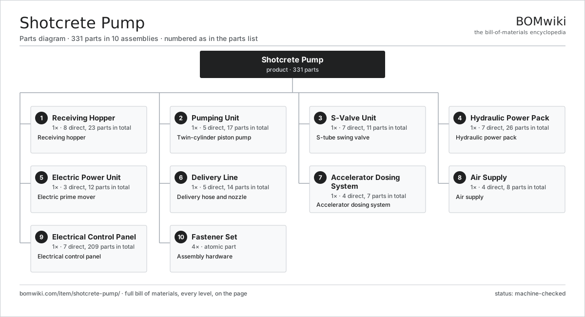
| # | Part | Qty | What it does |
|---|---|---|---|
| 1 | Receiving Hopper 8 parts | 1× | Receiving hopper |
| 2 | Pumping Unit 5 parts | 1× | Twin-cylinder piston pump |
| 3 | S-Valve Unit 7 parts | 1× | S-tube swing valve |
| 4 | Hydraulic Power Pack 7 parts | 1× | Hydraulic power pack |
| 5 | Electric Power Unit 3 parts | 1× | Electric prime mover |
| 6 | Delivery Line 5 parts | 1× | Delivery hose and nozzle |
| 7 | Accelerator Dosing System 4 parts | 1× | Accelerator dosing system |
| 8 | Air Supply 4 parts | 1× | Air supply |
| 9 | Electrical Control Panel 7 parts | 1× | Electrical control panel |
| 10 | Fastener Set | 4× | Assembly hardware |
3D model
No 3D model yet. Have a CAD file of this? Add a 3D model — STL renders right on this page; STEP, FreeCAD, and OpenSCAD sources are welcome too (openly licensed, like all 3D models on BOMwiki).
Build & assembly graph
expand / collapse · shared sub-assemblies converge · links to related products · est. labourTap an assembly to expand/collapse · tap a part to open it · use “Open page” for any node · drag to pan, scroll to zoom.
Bill of materials for Shotcrete Pump
10 top-level lines · 106 rows shown · 331 parts total · indented to 3 levels| # | Item / sub-assembly | Part no. | Qty/assy | Ext. qty | Parts | Type |
|---|---|---|---|---|---|---|
| 1 | Receiving Hopper 8 parts | shotcrete-pump-hopper | 1× | 1 | 23 | assembly |
| 1.1 | Hopper Shell | shotcrete-pump-hopper-shell | 1× | 1 | · | part |
| 1.2 | Agitator 3 parts | shotcrete-pump-agitator | 1× | 1 | 10 | assembly |
| 1.2.1 | Agitator Shaft | shotcrete-pump-agitator-shaft | 1× | 1 | · | part |
| 1.2.2 | Agitator Drive Motor 3 parts + deeper › | shotcrete-pump-agitator-motor | 1× | 1 | 3 | assembly |
| 1.2.3 | Remixer Paddle | shotcrete-pump-remixer-paddle | 6× | 6 | · | part |
| 1.3 | Protection Grate | shotcrete-pump-grate | 1× | 1 | · | part |
| 1.4 | Wear Liner | shotcrete-pump-hopper-liner | 2× | 2 | · | part |
| 1.5 | Remixer Paddle | shotcrete-pump-remixer-paddle | 4× | 4 | · | part |
| 1.6 | Hopper Level Sensor | shotcrete-pump-level-sensor | 1× | 1 | · | part |
| 1.7 | Ball Bearing | ball-bearing | 2× | 2 | · | part |
| 1.8 | Oil Seal | oil-seal | 2× | 2 | · | part |
| 2 | Pumping Unit 5 parts | shotcrete-pump-pumping-unit | 1× | 1 | 17 | assembly |
| 2.1 | Material Delivery Cylinder | shotcrete-pump-material-cylinder | 2× | 2 | · | part |
| 2.2 | Hydraulic Drive Cylinder 4 parts | shotcrete-pump-drive-cylinder | 2× | 2 | 5 | assembly |
| 2.2.1 | Cylinder Barrel | shotcrete-pump-cylinder-barrel | 1× | 2 | · | part |
| 2.2.2 | Piston Rod | shotcrete-pump-cylinder-rod | 1× | 2 | · | part |
| 2.2.3 | O-Ring Set | oring-set | 2× | 4 | · | part |
| 2.2.4 | Oil Seal | oil-seal | 1× | 2 | · | part |
| 2.3 | Concrete Piston | shotcrete-pump-pump-piston | 2× | 2 | · | part |
| 2.4 | Water Box | shotcrete-pump-water-box | 1× | 1 | · | part |
| 2.5 | Stroke End Sensor | shotcrete-pump-stroke-sensor | 2× | 2 | · | part |
| 3 | S-Valve Unit 7 parts | shotcrete-pump-s-valve-unit | 1× | 1 | 11 | assembly |
| 3.1 | S-Tube Swing Valve | shotcrete-pump-swing-tube | 1× | 1 | · | part |
| 3.2 | Swing Actuating Cylinder 2 parts | shotcrete-pump-swing-cylinder | 2× | 2 | 2 | assembly |
| 3.2.1 | Cylinder Barrel | shotcrete-pump-cylinder-barrel | 1× | 2 | · | part |
| 3.2.2 | O-Ring Set | oring-set | 1× | 2 | · | part |
| 3.3 | Wear Ring | shotcrete-pump-wear-ring | 1× | 1 | · | part |
| 3.4 | Cutting Ring | shotcrete-pump-cutting-ring | 1× | 1 | · | part |
| 3.5 | Outlet Flange | shotcrete-pump-outlet-flange | 1× | 1 | · | part |
| 3.6 | Swing Tube Bearing 1 parts | shotcrete-pump-swing-bearing | 1× | 1 | · | part |
| 3.6.1 | Ball Bearing | ball-bearing | 1× | 1 | · | part |
| 3.7 | Oil Seal | oil-seal | 2× | 2 | · | part |
| 4 | Hydraulic Power Pack 7 parts | shotcrete-pump-hydraulic-pack | 1× | 1 | 26 | assembly |
| 4.1 | Main Hydraulic Pump 4 parts | shotcrete-pump-main-pump | 1× | 1 | 5 | assembly |
| 4.1.1 | Rotating Group | shotcrete-pump-pump-rotor-group | 1× | 1 | · | part |
| 4.1.2 | Swashplate | shotcrete-pump-swashplate | 1× | 1 | · | part |
| 4.1.3 | Ball Bearing | ball-bearing | 2× | 2 | · | part |
| 4.1.4 | Oil Seal | oil-seal | 1× | 1 | · | part |
| 4.2 | Directional Valve Bank 4 parts | shotcrete-pump-valve-bank | 1× | 1 | 14 | assembly |
| 4.2.1 | Directional Valve | shotcrete-pump-directional-valve | 3× | 3 | · | part |
| 4.2.2 | Pressure Relief Valve | shotcrete-pump-relief-valve | 1× | 1 | · | part |
| 4.2.3 | Relay | relay | 4× | 4 | · | part |
| 4.2.4 | O-Ring Set | oring-set | 6× | 6 | · | part |
| 4.3 | Oil Cooler 2 parts | shotcrete-pump-oil-cooler | 1× | 1 | 2 | assembly |
| 4.3.1 | Cooler Core | shotcrete-pump-cooler-core | 1× | 1 | · | part |
| 4.3.2 | Cooler Fan | shotcrete-pump-cooler-fan | 1× | 1 | · | part |
| 4.4 | Hydraulic Tank | shotcrete-pump-oil-tank | 1× | 1 | · | part |
| 4.5 | Accumulator | shotcrete-pump-accumulator | 1× | 1 | · | part |
| 4.6 | Return Filter | shotcrete-pump-return-filter | 1× | 1 | · | part |
| 4.7 | Pressure Sensor | pressure-sensor | 2× | 2 | · | part |
| 5 | Electric Power Unit 3 parts | shotcrete-pump-power-unit | 1× | 1 | 12 | assembly |
| 5.1 | Electric Drive Motor 5 parts | shotcrete-pump-electric-motor | 1× | 1 | 6 | assembly |
| 5.1.1 | Motor Stator | shotcrete-pump-motor-stator | 1× | 1 | · | part |
| 5.1.2 | Motor Rotor | shotcrete-pump-motor-rotor | 1× | 1 | · | part |
| 5.1.3 | Motor Housing | shotcrete-pump-motor-housing | 1× | 1 | · | part |
| 5.1.4 | Ball Bearing | ball-bearing | 2× | 2 | · | part |
| 5.1.5 | Motor Cooling Fan | shotcrete-pump-cooling-fan | 1× | 1 | · | part |
| 5.2 | Pump Coupling | shotcrete-pump-motor-coupling | 1× | 1 | · | part |
| 5.3 | Motor Starter 2 parts | shotcrete-pump-motor-starter | 1× | 1 | · | part |
| 5.3.1 | Relay | relay | 3× | 3 | · | part |
| 5.3.2 | Contactor | shotcrete-pump-contactor | 2× | 2 | · | part |
| 6 | Delivery Line 5 parts | shotcrete-pump-delivery-line | 1× | 1 | 14 | assembly |
| 6.1 | Delivery Hose | shotcrete-pump-delivery-hose | 1× | 1 | · | part |
| 6.2 | Line Reducer | shotcrete-pump-reducer | 2× | 2 | · | part |
| 6.3 | Pipe Coupling | shotcrete-pump-pipe-coupling | 6× | 6 | · | part |
| 6.4 | Spray Nozzle 4 parts | shotcrete-pump-nozzle | 1× | 1 | 4 | assembly |
| 6.4.1 | Nozzle Body | shotcrete-pump-nozzle-body | 1× | 1 | · | part |
| 6.4.2 | Rubber Tip | shotcrete-pump-nozzle-tip | 1× | 1 | · | part |
| 6.4.3 | Air and Accelerator Ring | shotcrete-pump-injection-ring | 1× | 1 | · | part |
| 6.4.4 | Air Valve | shotcrete-pump-nozzle-valve | 1× | 1 | · | part |
| 6.5 | Air and Accelerator Ring | shotcrete-pump-injection-ring | 1× | 1 | · | part |
| 7 | Accelerator Dosing System 4 parts | shotcrete-pump-accelerator-system | 1× | 1 | 7 | assembly |
| 7.1 | Accelerator Tank | shotcrete-pump-accel-tank | 1× | 1 | · | part |
| 7.2 | Dosing Pump 3 parts | shotcrete-pump-dosing-pump | 1× | 1 | 4 | assembly |
| 7.2.1 | Squeeze Hose | shotcrete-pump-dosing-hose | 1× | 1 | · | part |
| 7.2.2 | Roller Rotor | shotcrete-pump-dosing-rotor | 1× | 1 | · | part |
| 7.2.3 | Dosing Drive Motor 2 parts + deeper › | shotcrete-pump-dosing-motor | 1× | 1 | · | part |
| 7.3 | Accelerator Flow Meter | shotcrete-pump-accel-flow-meter | 1× | 1 | · | part |
| 7.4 | Accelerator Hose | shotcrete-pump-accel-hose | 1× | 1 | · | part |
| 8 | Air Supply 4 parts | shotcrete-pump-air-system | 1× | 1 | 8 | assembly |
| 8.1 | Air Compressor 4 parts | shotcrete-pump-air-compressor | 1× | 1 | 5 | assembly |
| 8.1.1 | Compressor Block | shotcrete-pump-compressor-block | 1× | 1 | · | part |
| 8.1.2 | Motor Cooling Fan | shotcrete-pump-cooling-fan | 1× | 1 | · | part |
| 8.1.3 | Ball Bearing | ball-bearing | 2× | 2 | · | part |
| 8.1.4 | Oil Seal | oil-seal | 1× | 1 | · | part |
| 8.2 | Air Receiver | shotcrete-pump-air-receiver | 1× | 1 | · | part |
| 8.3 | Air Regulator | shotcrete-pump-air-regulator | 1× | 1 | · | part |
| 8.4 | Air Hose | shotcrete-pump-air-hose | 1× | 1 | · | part |
| 9 | Electrical Control Panel 7 parts | shotcrete-pump-control-panel | 1× | 1 | 209 | assembly |
| 9.1 | PLC Controller 4 parts | shotcrete-pump-controller | 1× | 1 | 148 | assembly |
| 9.1.1 | Bare PCB | pcb-bare | 1× | 1 | · | part |
| 9.1.2 | Microcontroller | mcu | 1× | 1 | · | part |
| 9.1.3 | Relay | relay | 6× | 6 | · | part |
| 9.1.4 | SMD Passive (R/C/L) | smd-passives | 140× | 140 | · | part |
| 9.2 | Operator Display 2 parts | shotcrete-pump-display | 1× | 1 | 41 | assembly |
| 9.2.1 | Bare PCB | pcb-bare | 1× | 1 | · | part |
| 9.2.2 | SMD Passive (R/C/L) | smd-passives | 40× | 40 | · | part |
| 9.3 | Cabled Remote Control 2 parts | shotcrete-pump-remote | 1× | 1 | · | part |
| 9.3.1 | Wire Bundle | wire-bundle | 1× | 1 | · | part |
| 9.3.2 | Connector | connector | 2× | 2 | · | part |
| 9.4 | Power Supply | power-supply | 1× | 1 | · | part |
| 9.5 | Wire Bundle | wire-bundle | 2× | 2 | · | part |
| 9.6 | Connector | connector | 12× | 12 | · | part |
| 9.7 | Emergency Stop | shotcrete-pump-estop | 2× | 2 | · | part |
| 10 | Fastener Set | fastener-set | 4× | 4 | · | part |
Related products
same domain, ranked by shared parts Asphalt Recycler
226 parts · shares 10 with this page
Bridge Form Traveler
405 parts · shares 10 with this page
Asphalt Recycler
226 parts · shares 10 with this page
Bridge Form Traveler
405 parts · shares 10 with this page
 Bridge Girder Launching Gantry
1,542 parts · shares 10 with this page
Bridge Girder Launching Gantry
1,542 parts · shares 10 with this page
 Cold In-Place Recycling Train
657 parts · shares 10 with this page
Concrete Reclaimer Plant
154 parts · shares 10 with this page
Cold In-Place Recycling Train
657 parts · shares 10 with this page
Concrete Reclaimer Plant
154 parts · shares 10 with this page
 Diaphragm Wall Cutter
440 parts · shares 10 with this page
Diaphragm Wall Cutter
440 parts · shares 10 with this page
Sourcing: possible vendors
Prices, MOQ, and lead times are algorithmic estimates, not quotes, and not claims about these companies. Company mappings are curated by keyword; est. price band $15k–$2M. How estimates work| Vendor | HQ | Specialty | MOQ | Lead time |
|---|---|---|---|---|
| caterpillar.com ↗ | Irving, US | Construction & mining equipment | made to order | 16–28 wks |
|
🇯🇵Komatsu
komatsu.com ↗
|
Tokyo, JP | Construction & mining equipment | made to order | 16–28 wks |
|
🇸🇪Volvo CE
volvoce.com ↗
|
Gothenburg, SE | Construction equipment | made to order | 16–28 wks |
|
🇨🇭Liebherr
liebherr.com ↗
|
Bulle, CH | Cranes & heavy equipment | made to order | 16–28 wks |
|
🇨🇳XCMG
xcmg.com ↗
|
Xuzhou, CN | Construction machinery | made to order | 16–28 wks |
1,067-word article