Segmental Bridge Erection Gantry
ProductOverview
A segmental bridge erection gantry is a self-launching steel machine that builds long-span concrete bridges from precast box-girder segments. It sits on top of the bridge it is building, spans from one pier to the next, lifts each segment up from a barge or transporter below, and positions it to within a few millimetres so the segment can be glued and stressed to the cantilever already in place. When a span is finished, the gantry walks itself forward to the next pier without any assist crane.
The machine is used for the balanced-cantilever method. Construction starts at a pier and segments are added in pairs, one on each side of the pier, so the growing structure stays roughly balanced about the pier. Each segment is typically 2.5 to 4 m long and weighs 60 to 250 t. The Segment Winch Trolley picks up the segment, runs it along the truss to the free end of the cantilever, and holds it while the joint is made.
Main Truss
The Main Girder Truss is the spine of the gantry. It is a pair of welded box-section trusses, usually 60 to 130 m long, made from Welded Truss Module units of 8 to 12 m that bolt together at site through 30 to 40 mm Bolted Splice Plate connections. The truss must be longer than one span, because while one span is being built the truss has to reach across to the next pier to land on it before launching. Lateral Lateral Bracing Frame members tie the two trusses together and carry wind and torsion loads.
Along the top chord runs a hardened Top Chord Trolley Rail, a crane rail on which the lifting trolleys travel. Plate thickness in the truss modules ranges from 20 to 40 mm in S355 structural steel, and each module weighs 12 to 20 t, which sets the size of the assembly crane needed to erect the gantry at the start of the job.
Support Legs
The Support Leg Set carry the whole machine and the segment being lifted down into the completed deck and the pier. There are normally three: a front leg that reaches ahead to the next pier, a mid leg over the pier currently being built around, and a rear leg standing on the finished deck. Each Leg Column is a box section of 1.2 to 1.8 m square carrying axial loads up to 6000 kN.
The legs are not simply set down. Because the load on a cantilever is heavily one-sided during construction, the legs have to resist uplift and overturning. The Deck Clamping Base clamps to the deck using Through-Deck Clamp Bar tension bars that pass through ducts cast into the slab, holding the leg down against uplift of up to 2500 kN. The Base Spreader Plate under each leg spreads the downward load so the bearing pressure on the young concrete stays below 15 MPa. Each leg sits on Leg Levelling Jack cylinders that level the gantry and transfer load gradually, and a mechanical Mechanical Lock Nut holds the load without relying on hydraulic pressure once the leg is set.
Self-Launching System
When a span is complete, the Self-Launching System moves the gantry forward by one span. The truss rests on Articulated Roller Bogie bogies, each an equalising frame on hardened Launch Roller Wheel rollers running on a stainless-faced Launch Skid Track. Long-stroke Launch Push-Pull Cylinder units pull the truss along: a Friction Gripper clamps the truss web, the cylinder extends to drag the gantry forward 1.5 to 2 m, then the gripper releases and the cylinder retracts for the next bite. A typical launch of one span takes a few hours and is the most carefully watched operation in the cycle, because the front of the gantry is cantilevered far out ahead of the support before it lands on the new pier.
Lifting and Positioning
Each Segment Winch Trolley carries two Hoist Winch units. A winch uses a grooved Grooved Rope Drum storing multi-fall Hoist Wire Rope of 26 to 40 mm diameter, with a 5:1 minimum safety factor on breaking load. A spring-applied Winch Brake holds the segment if power is lost. The segment is picked up through a Segment Lifting Beam spreader whose Pick-Point Shackle shackles match the lifting loops cast into the segment. Fine positioning uses the trolley travel and the hoist together so the new segment lines up with the matching face of the previous one to within a couple of millimetres before the epoxy joint is closed.
Hydraulics, Power and Control
The Hydraulic Power Unit unit runs the legs, the launch cylinders and the grippers. A variable Hydraulic Pump feeds 350 bar through a Proportional Valve Manifold of Proportional Control Valve proportional valves and Load-Holding Check Valve load-holding valves, so the leg cylinders rise together and stay locked if a hose fails. Oil is kept under 60 C by an Air-Blast Oil Cooler.
The Control and Monitoring System is built around a safety PLC in the PLC Control Cabinet, reading Load Cell cells on the legs and hoists, Inclinometer sensors on the truss, and an Anemometer that stops work above the rated wind. The operator works from the Operator Cabin using Ball Bearing supported trolleys and proportional Control Joystick controls, with travel and hoist driven by Servo Motor units through the Electrical Power System system. Erection rates of one segment pair per day are common once a crew is in rhythm, and a long viaduct of several hundred segments can be built by a single gantry over many months.
Segmental Bridge Erection Gantry parts and their functions
7 top-level parts · 847 parts in total · full bill of materials below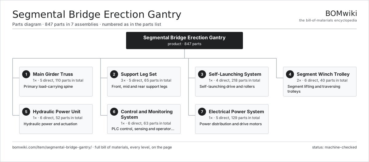
| # | Part | Qty | What it does |
|---|---|---|---|
| 1 | Main Girder Truss 5 parts | 1× | Primary load-carrying spine |
| 2 | Support Leg Set 5 parts | 3× | Front, mid and rear support legs |
| 3 | Self-Launching System 4 parts | 1× | Self-launching drive and rollers |
| 4 | Segment Winch Trolley 6 parts | 2× | Segment lifting and traversing trolleys |
| 5 | Hydraulic Power Unit 6 parts | 1× | Hydraulic power and actuation |
| 6 | Control and Monitoring System 6 parts | 1× | PLC control, sensing and operator station |
| 7 | Electrical Power System 5 parts | 1× | Power distribution and drive motors |
3D model
No 3D model yet. Have a CAD file of this? Add a 3D model — STL renders right on this page; STEP, FreeCAD, and OpenSCAD sources are welcome too (openly licensed, like all 3D models on BOMwiki).
Build & assembly graph
expand / collapse · shared sub-assemblies converge · links to related products · est. labourTap an assembly to expand/collapse · tap a part to open it · use “Open page” for any node · drag to pan, scroll to zoom.
Bill of materials for Segmental Bridge Erection Gantry
7 top-level lines · 86 rows shown · 847 parts total · indented to 3 levels| # | Item / sub-assembly | Part no. | Qty/assy | Ext. qty | Parts | Type |
|---|---|---|---|---|---|---|
| 1 | Main Girder Truss 5 parts | segmental-bridge-gantry-main-truss | 1× | 1 | 110 | assembly |
| 1.1 | Welded Truss Module | segmental-bridge-gantry-truss-module | 8× | 8 | · | part |
| 1.2 | Top Chord Trolley Rail | segmental-bridge-gantry-top-flange-rail | 2× | 2 | · | part |
| 1.3 | Lateral Bracing Frame | segmental-bridge-gantry-bracing-frame | 12× | 12 | · | part |
| 1.4 | Bolted Splice Plate | segmental-bridge-gantry-splice-plate | 28× | 28 | · | part |
| 1.5 | Fastener Set | fastener-set | 60× | 60 | · | part |
| 2 | Support Leg Set 5 parts | segmental-bridge-gantry-support-legs | 3× | 3 | 65 | assembly |
| 2.1 | Leg Column | segmental-bridge-gantry-leg-column | 3× | 9 | · | part |
| 2.2 | Leg Levelling Jack 3 parts | segmental-bridge-gantry-leg-jack | 6× | 18 | 3 | assembly |
| 2.2.1 | Jack Cylinder | segmental-bridge-gantry-jack-cylinder | 1× | 18 | · | part |
| 2.2.2 | Mechanical Lock Nut | segmental-bridge-gantry-lock-nut | 1× | 18 | · | part |
| 2.2.3 | O-Ring Set | oring-set | 1× | 18 | · | part |
| 2.3 | Leg Top Saddle | segmental-bridge-gantry-leg-saddle | 3× | 9 | · | part |
| 2.4 | Deck Clamping Base 3 parts | segmental-bridge-gantry-leg-base | 3× | 9 | 13 | assembly |
| 2.4.1 | Through-Deck Clamp Bar | segmental-bridge-gantry-clamp-bar | 4× | 36 | · | part |
| 2.4.2 | Base Spreader Plate | segmental-bridge-gantry-base-plate | 1× | 9 | · | part |
| 2.4.3 | Fastener Set | fastener-set | 8× | 72 | · | part |
| 2.5 | Transverse Skid Beam | segmental-bridge-gantry-cross-traverse | 2× | 6 | · | part |
| 3 | Self-Launching System 4 parts | segmental-bridge-gantry-launching-system | 1× | 1 | 218 | assembly |
| 3.1 | Articulated Roller Bogie 3 parts | segmental-bridge-gantry-launch-roller | 8× | 8 | 25 | assembly |
| 3.1.1 | Launch Roller Wheel | segmental-bridge-gantry-roller-wheel | 8× | 64 | · | part |
| 3.1.2 | Ball Bearing | ball-bearing | 16× | 128 | · | part |
| 3.1.3 | Equalising Bogie Frame | segmental-bridge-gantry-bogie-frame | 1× | 8 | · | part |
| 3.2 | Launch Push-Pull Cylinder 3 parts | segmental-bridge-gantry-launch-cylinder | 4× | 4 | 3 | assembly |
| 3.2.1 | Launch Cylinder Body | segmental-bridge-gantry-launch-cyl-body | 1× | 4 | · | part |
| 3.2.2 | O-Ring Set | oring-set | 1× | 4 | · | part |
| 3.2.3 | Pressure Sensor | pressure-sensor | 1× | 4 | · | part |
| 3.3 | Friction Gripper | segmental-bridge-gantry-gripper | 4× | 4 | · | part |
| 3.4 | Launch Skid Track | segmental-bridge-gantry-skid-track | 2× | 2 | · | part |
| 4 | Segment Winch Trolley 6 parts | segmental-bridge-gantry-winch-trolley | 2× | 2 | 40 | assembly |
| 4.1 | Trolley Frame | segmental-bridge-gantry-trolley-frame | 1× | 2 | · | part |
| 4.2 | Hoist Winch 6 parts | segmental-bridge-gantry-hoist-winch | 2× | 4 | 11 | assembly |
| 4.2.1 | Grooved Rope Drum | segmental-bridge-gantry-winch-drum | 1× | 4 | · | part |
| 4.2.2 | Hoist Wire Rope | segmental-bridge-gantry-wire-rope | 1× | 4 | · | part |
| 4.2.3 | Winch Brake | segmental-bridge-gantry-winch-brake | 2× | 8 | · | part |
| 4.2.4 | Gearbox Housing | gearbox-housing | 1× | 4 | · | part |
| 4.2.5 | Helical Gear Pair | gear-pair | 2× | 8 | · | part |
| 4.2.6 | Ball Bearing | ball-bearing | 4× | 16 | · | part |
| 4.3 | Trolley Running Wheel | segmental-bridge-gantry-trolley-wheel | 4× | 8 | · | part |
| 4.4 | Segment Lifting Beam 3 parts | segmental-bridge-gantry-lifting-beam | 1× | 2 | 9 | assembly |
| 4.4.1 | Pick-Point Shackle | segmental-bridge-gantry-pick-shackle | 4× | 8 | · | part |
| 4.4.2 | Spreader Beam Girder | segmental-bridge-gantry-beam-girder | 1× | 2 | · | part |
| 4.4.3 | Fastener Set | fastener-set | 4× | 8 | · | part |
| 4.5 | Gearbox Housing | gearbox-housing | 2× | 4 | · | part |
| 4.6 | Helical Gear Pair | gear-pair | 2× | 4 | · | part |
| 5 | Hydraulic Power Unit 6 parts | segmental-bridge-gantry-hydraulic-power | 1× | 1 | 52 | assembly |
| 5.1 | Hydraulic Pump | segmental-bridge-gantry-hyd-pump | 2× | 2 | · | part |
| 5.2 | Reservoir and Cooler 2 parts | segmental-bridge-gantry-hyd-tank | 1× | 1 | 3 | assembly |
| 5.2.1 | Air-Blast Oil Cooler | segmental-bridge-gantry-oil-cooler | 1× | 1 | · | part |
| 5.2.2 | Return Line Filter | segmental-bridge-gantry-return-filter | 2× | 2 | · | part |
| 5.3 | Proportional Valve Manifold 3 parts | segmental-bridge-gantry-hyd-manifold | 4× | 4 | 9 | assembly |
| 5.3.1 | Proportional Control Valve | segmental-bridge-gantry-prop-valve | 4× | 16 | · | part |
| 5.3.2 | Load-Holding Check Valve | segmental-bridge-gantry-check-valve | 4× | 16 | · | part |
| 5.3.3 | O-Ring Set | oring-set | 1× | 4 | · | part |
| 5.4 | High Pressure Hose Set | segmental-bridge-gantry-hyd-hose | 1× | 1 | · | part |
| 5.5 | Pressure Sensor | pressure-sensor | 8× | 8 | · | part |
| 5.6 | O-Ring Set | oring-set | 2× | 2 | · | part |
| 6 | Control and Monitoring System 6 parts | segmental-bridge-gantry-control-system | 1× | 1 | 63 | assembly |
| 6.1 | PLC Control Cabinet 6 parts | segmental-bridge-gantry-plc-cabinet | 1× | 1 | 41 | assembly |
| 6.1.1 | Bare PCB | pcb-bare | 4× | 4 | · | part |
| 6.1.2 | Microcontroller | mcu | 2× | 2 | · | part |
| 6.1.3 | SMD Passive (R/C/L) | smd-passives | 1× | 1 | · | part |
| 6.1.4 | Relay | relay | 12× | 12 | · | part |
| 6.1.5 | Connector | connector | 20× | 20 | · | part |
| 6.1.6 | Power Supply | power-supply | 2× | 2 | · | part |
| 6.2 | Operator Cabin 3 parts | segmental-bridge-gantry-operator-cabin | 1× | 1 | 10 | assembly |
| 6.2.1 | LCD Panel | lcd-panel | 2× | 2 | · | part |
| 6.2.2 | Control Joystick | segmental-bridge-gantry-joystick | 2× | 2 | · | part |
| 6.2.3 | Sheet Metal Panel | sheet-panel | 6× | 6 | · | part |
| 6.3 | Load Cell | segmental-bridge-gantry-load-cell | 6× | 6 | · | part |
| 6.4 | Inclinometer | segmental-bridge-gantry-inclinometer | 4× | 4 | · | part |
| 6.5 | Anemometer | segmental-bridge-gantry-anemometer | 1× | 1 | · | part |
| 6.6 | Wire Bundle | wire-bundle | 1× | 1 | · | part |
| 7 | Electrical Power System 5 parts | segmental-bridge-gantry-electrical | 1× | 1 | 129 | assembly |
| 7.1 | Main Distribution Panel 3 parts | segmental-bridge-gantry-main-panel | 1× | 1 | 26 | assembly |
| 7.1.1 | Moulded Case Breaker | segmental-bridge-gantry-breaker | 6× | 6 | · | part |
| 7.1.2 | Relay | relay | 8× | 8 | · | part |
| 7.1.3 | Connector | connector | 12× | 12 | · | part |
| 7.2 | Variable Frequency Drive | segmental-bridge-gantry-vfd | 4× | 4 | · | part |
| 7.3 | Servo Motor 4 parts | servo-motor | 4× | 4 | 24 | assembly |
| 7.3.1 | Stator Assembly 3 parts + deeper › | stator-assembly | 1× | 4 | 3 | assembly |
| 7.3.2 | Rotor Assembly 4 parts + deeper › | rotor-assembly | 1× | 4 | 19 | assembly |
| 7.3.3 | Encoder | encoder | 1× | 4 | · | part |
| 7.3.4 | Motor Housing | motor-housing | 1× | 4 | · | part |
| 7.4 | Trailing Cable Reel | segmental-bridge-gantry-cable-reel | 1× | 1 | · | part |
| 7.5 | Wire Bundle | wire-bundle | 2× | 2 | · | part |
Related products
same domain, ranked by shared parts Bridge Girder Launching Gantry
1,542 parts · shares 23 with this page
Bridge Girder Launching Gantry
1,542 parts · shares 23 with this page
 Flat-Top Tower Crane
358 parts · shares 23 with this page
Flat-Top Tower Crane
358 parts · shares 23 with this page
 Tandem Vibratory Roller
369 parts · shares 23 with this page
Tandem Vibratory Roller
369 parts · shares 23 with this page
 Tracked Asphalt Paver
1,299 parts · shares 23 with this page
Rebar Shearing and Bending Line
361 parts · shares 22 with this page
Tracked Asphalt Paver
1,299 parts · shares 23 with this page
Rebar Shearing and Bending Line
361 parts · shares 22 with this page
 Asphalt Recycler
226 parts · shares 22 with this page
Asphalt Recycler
226 parts · shares 22 with this page
Sourcing: possible vendors
Prices, MOQ, and lead times are algorithmic estimates, not quotes, and not claims about these companies. Company mappings are curated by keyword; est. price band $15k–$2M. How estimates work| Vendor | HQ | Specialty | MOQ | Lead time |
|---|---|---|---|---|
| caterpillar.com ↗ | Irving, US | Construction & mining equipment | made to order | 16–28 wks |
|
🇯🇵Komatsu
komatsu.com ↗
|
Tokyo, JP | Construction & mining equipment | made to order | 16–28 wks |
|
🇸🇪Volvo CE
volvoce.com ↗
|
Gothenburg, SE | Construction equipment | made to order | 16–28 wks |
|
🇨🇭Liebherr
liebherr.com ↗
|
Bulle, CH | Cranes & heavy equipment | made to order | 16–28 wks |
|
🇨🇳XCMG
xcmg.com ↗
|
Xuzhou, CN | Construction machinery | made to order | 16–28 wks |
1,030-word article