Bridge Form Traveler
ProductOverview
A bridge form traveler is a movable formwork carriage used to build long-span concrete bridges segment by segment, cast in place rather than precast. It is the cast-in-situ counterpart to the precast erection gantry. The traveler clamps to the end of the cantilever already built, hangs the formwork for the next segment off an overhead frame, holds it while the segment is reinforced and poured, waits for the concrete to gain strength, then strips the formwork and rolls itself forward to cast the next segment.
Form travelers are used in pairs, one working out from each side of a pier, so the balanced-cantilever structure stays roughly symmetric about the pier as it grows. Each casting cycle adds 3 to 5 m of bridge and takes about a week including curing and stressing. A typical traveler weighs 60 to 180 t and has to carry 150 to 400 t of wet concrete and formwork as a cantilevered load hanging off the front of the finished deck.
Overhead Main Truss
The Overhead Main Truss carries the entire formwork weight and the wet concrete. It is a pair of A-frame trusses, with inclined A-Frame Leg legs of 6 to 9 m feeding load down to the rails, Top Longitudinal Beam longitudinal beams from which the formwork hangs, and Transverse Cross Beam transverse beams tying the two frames together. Diagonal Truss Bracing Member members resist wind and, more importantly, the eccentric load that comes from pouring concrete on one side at a time. The truss rolls forward on Launch Running Rail rails bolted to the deck that was cast in the previous cycle.
Rail and Anchor System
Because the concrete load hangs out in front of the support, the traveler would tip forward if it were not tied down. The Rail and Anchor System handles this. The traveler runs on Travel Roller Bogie bogies fitted with hardened Roller Wheel wheels and a Bogie Pivot that equalises the load between rollers. The whole assembly is held down by Through-Deck Tie-Down Bar high-tensile bars that pass through the deck and resist uplift of up to 1500 kN each, reacting through an Rail Anchor Shoe into the slab. During casting the traveler is locked to the rail by a Rail Clamping Jaw so it cannot creep under the changing load, and the clamp releases only when the traveler is ready to launch forward.
Box-Girder Formwork
The Box-Girder Formwork shapes the box-girder cross section of each segment. The Outer Form Panel panels carry the side webs and the wing soffit. They are stiffened by Form Stiffening Rib ribs that keep deflection under wet concrete pressure below 2 mm, and they hinge on Stripping Hinge joints so the form can swing 100 to 200 mm clear of the cured segment before the traveler advances.
The hardest part of the formwork to design is the inside of the box. The Inner Core Form has to come out through the segment once the concrete has set, so it is collapsible: a Inner Form Collapse Link toggle linkage retracts the inner panels inward by 80 to 150 mm so the core form can be withdrawn and dragged forward. The Segment End Bulkhead forms the end face of each segment and carries the formers for the post-tensioning ducts that will later be threaded with tendons. The Form Face Skin is a machined steel face, 5 to 8 mm thick, that gives a smooth concrete finish and is reused for 100 or more casting cycles. Each panel is set to line and level by Form Positioning Jack jacks driven through a precision Ball Screw for repeatable positioning.
Suspension and Access
The formwork hangs below the truss on the Suspension and Access system. Vertical Suspension Hanger Bar bars carry the load down to Lower Suspension Beam beams that spread it across the soffit form. A Hanger Levelling Jack cylinder on each hanger sets and holds the soffit level to within 3 mm, which matters because the geometry of every segment has to match the design camber so the two cantilevers meet correctly at midspan. Crews reach the formwork on Access Walkway platforms made of Walkway Grating grating with Handrail Section guarding at a 1.1 m height.
Launch, Hydraulics and Control
When a segment has cured and been stressed, the Self-Launching Drive advances the traveler one segment length. A Rail Gripper clamps the rail and a Launch Push Cylinder pulls the traveler forward 1 to 1.5 m per stroke, with a Travel Drive Unit for fine creep during alignment. The Hydraulic Power Unit unit feeds the launch cylinders, the form jacks and the hanger jacks through a Valve Manifold of Directional Valve directional valves and Load-Holding Check Valve load-holding valves, so the formwork stays put if pressure is lost. Oil is kept clean by a Return Line Filter and dry by a Tank Breather.
Control comes from a PLC in the PLC Control Cabinet, built on Bare PCB boards with an Microcontroller processor, reading Load Cell cells on the hangers and rail anchors and Inclinometer sensors on the truss to watch the tilt during an unbalanced pour. The operator drives jacking and launch from a Operator Pendant with hold-to-run Command Pushbutton controls. Segment geometry is set by reading Geometry Survey Target targets with a total station and adjusting the form jacks until each new segment lands on the design line and the design camber.
Bridge Form Traveler parts and their functions
7 top-level parts · 405 parts in total · full bill of materials below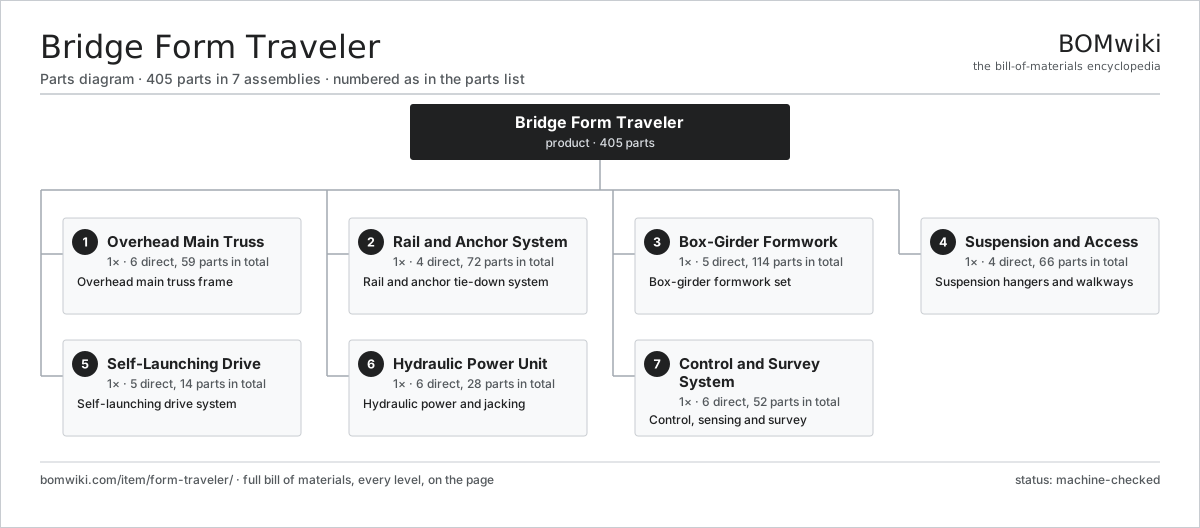
| # | Part | Qty | What it does |
|---|---|---|---|
| 1 | Overhead Main Truss 6 parts | 1× | Overhead main truss frame |
| 2 | Rail and Anchor System 4 parts | 1× | Rail and anchor tie-down system |
| 3 | Box-Girder Formwork 5 parts | 1× | Box-girder formwork set |
| 4 | Suspension and Access 4 parts | 1× | Suspension hangers and walkways |
| 5 | Self-Launching Drive 5 parts | 1× | Self-launching drive system |
| 6 | Hydraulic Power Unit 6 parts | 1× | Hydraulic power and jacking |
| 7 | Control and Survey System 6 parts | 1× | Control, sensing and survey |
3D model
No 3D model yet. Have a CAD file of this? Add a 3D model — STL renders right on this page; STEP, FreeCAD, and OpenSCAD sources are welcome too (openly licensed, like all 3D models on BOMwiki).
Build & assembly graph
expand / collapse · shared sub-assemblies converge · links to related products · est. labourTap an assembly to expand/collapse · tap a part to open it · use “Open page” for any node · drag to pan, scroll to zoom.
Bill of materials for Bridge Form Traveler
7 top-level lines · 73 rows shown · 405 parts total · indented to 3 levels| # | Item / sub-assembly | Part no. | Qty/assy | Ext. qty | Parts | Type |
|---|---|---|---|---|---|---|
| 1 | Overhead Main Truss 6 parts | form-traveler-main-truss | 1× | 1 | 59 | assembly |
| 1.1 | A-Frame Leg | form-traveler-truss-leg | 4× | 4 | · | part |
| 1.2 | Top Longitudinal Beam | form-traveler-top-beam | 2× | 2 | · | part |
| 1.3 | Transverse Cross Beam | form-traveler-cross-beam | 3× | 3 | · | part |
| 1.4 | Launch Running Rail | form-traveler-running-rail | 2× | 2 | · | part |
| 1.5 | Truss Bracing Member | form-traveler-bracing | 8× | 8 | · | part |
| 1.6 | Fastener Set | fastener-set | 40× | 40 | · | part |
| 2 | Rail and Anchor System 4 parts | form-traveler-anchor-system | 1× | 1 | 72 | assembly |
| 2.1 | Travel Roller Bogie 3 parts | form-traveler-roller-bogie | 4× | 4 | 13 | assembly |
| 2.1.1 | Roller Wheel | form-traveler-roller-wheel | 4× | 16 | · | part |
| 2.1.2 | Ball Bearing | ball-bearing | 8× | 32 | · | part |
| 2.1.3 | Bogie Pivot | form-traveler-bogie-pivot | 1× | 4 | · | part |
| 2.2 | Through-Deck Tie-Down Bar | form-traveler-tie-down-bar | 8× | 8 | · | part |
| 2.3 | Rail Anchor Shoe | form-traveler-anchor-shoe | 8× | 8 | · | part |
| 2.4 | Rail Clamping Jaw | form-traveler-rail-clamp | 4× | 4 | · | part |
| 3 | Box-Girder Formwork 5 parts | form-traveler-formwork | 1× | 1 | 114 | assembly |
| 3.1 | Outer Form Panel 3 parts | form-traveler-outer-form | 2× | 2 | 32 | assembly |
| 3.1.1 | Sheet Metal Panel | sheet-panel | 12× | 24 | · | part |
| 3.1.2 | Form Stiffening Rib | form-traveler-form-rib | 16× | 32 | · | part |
| 3.1.3 | Stripping Hinge | form-traveler-strip-hinge | 4× | 8 | · | part |
| 3.2 | Inner Core Form 3 parts | form-traveler-inner-form | 1× | 1 | 24 | assembly |
| 3.2.1 | Sheet Metal Panel | sheet-panel | 8× | 8 | · | part |
| 3.2.2 | Inner Form Collapse Link | form-traveler-collapse-link | 4× | 4 | · | part |
| 3.2.3 | Form Positioning Jack 3 parts + deeper › | form-traveler-form-jack | 4× | 4 | 3 | assembly |
| 3.3 | Segment End Bulkhead | form-traveler-bulkhead | 1× | 1 | · | part |
| 3.4 | Form Face Skin | form-traveler-form-skin | 1× | 1 | · | part |
| 3.5 | Form Positioning Jack 3 parts | form-traveler-form-jack | 8× | 8 | 3 | assembly |
| 3.5.1 | Jack Adjustment Screw | form-traveler-jack-screw | 1× | 8 | · | part |
| 3.5.2 | Ball Screw | ball-screw | 1× | 8 | · | part |
| 3.5.3 | O-Ring Set | oring-set | 1× | 8 | · | part |
| 4 | Suspension and Access 4 parts | form-traveler-suspension | 1× | 1 | 66 | assembly |
| 4.1 | Suspension Hanger Bar | form-traveler-hanger-bar | 12× | 12 | · | part |
| 4.2 | Lower Suspension Beam | form-traveler-suspension-beam | 2× | 2 | · | part |
| 4.3 | Access Walkway 2 parts | form-traveler-walkway | 4× | 4 | 12 | assembly |
| 4.3.1 | Walkway Grating | form-traveler-grating | 4× | 16 | · | part |
| 4.3.2 | Handrail Section | form-traveler-handrail | 8× | 32 | · | part |
| 4.4 | Hanger Levelling Jack | form-traveler-hanger-jack | 4× | 4 | · | part |
| 5 | Self-Launching Drive 5 parts | form-traveler-launch-drive | 1× | 1 | 14 | assembly |
| 5.1 | Launch Push Cylinder 3 parts | form-traveler-launch-cylinder | 2× | 2 | 3 | assembly |
| 5.1.1 | Launch Cylinder Body | form-traveler-launch-cyl-body | 1× | 2 | · | part |
| 5.1.2 | O-Ring Set | oring-set | 1× | 2 | · | part |
| 5.1.3 | Pressure Sensor | pressure-sensor | 1× | 2 | · | part |
| 5.2 | Rail Gripper | form-traveler-launch-gripper | 2× | 2 | · | part |
| 5.3 | Travel Drive Unit | form-traveler-drive-motor | 2× | 2 | · | part |
| 5.4 | Gearbox Housing | gearbox-housing | 2× | 2 | · | part |
| 5.5 | Helical Gear Pair | gear-pair | 2× | 2 | · | part |
| 6 | Hydraulic Power Unit 6 parts | form-traveler-hydraulic-power | 1× | 1 | 28 | assembly |
| 6.1 | Hydraulic Pump | form-traveler-hyd-pump | 1× | 1 | · | part |
| 6.2 | Reservoir and Filtration 2 parts | form-traveler-hyd-tank | 1× | 1 | 2 | assembly |
| 6.2.1 | Return Line Filter | form-traveler-return-filter | 1× | 1 | · | part |
| 6.2.2 | Tank Breather | form-traveler-breather | 1× | 1 | · | part |
| 6.3 | Valve Manifold 3 parts | form-traveler-hyd-manifold | 2× | 2 | 9 | assembly |
| 6.3.1 | Directional Valve | form-traveler-dir-valve | 4× | 8 | · | part |
| 6.3.2 | Load-Holding Check Valve | form-traveler-check-valve | 4× | 8 | · | part |
| 6.3.3 | O-Ring Set | oring-set | 1× | 2 | · | part |
| 6.4 | Hydraulic Hose Set | form-traveler-hyd-hose | 1× | 1 | · | part |
| 6.5 | Pressure Sensor | pressure-sensor | 4× | 4 | · | part |
| 6.6 | O-Ring Set | oring-set | 2× | 2 | · | part |
| 7 | Control and Survey System 6 parts | form-traveler-control-system | 1× | 1 | 52 | assembly |
| 7.1 | PLC Control Cabinet 6 parts | form-traveler-plc-cabinet | 1× | 1 | 30 | assembly |
| 7.1.1 | Bare PCB | pcb-bare | 3× | 3 | · | part |
| 7.1.2 | Microcontroller | mcu | 1× | 1 | · | part |
| 7.1.3 | SMD Passive (R/C/L) | smd-passives | 1× | 1 | · | part |
| 7.1.4 | Relay | relay | 8× | 8 | · | part |
| 7.1.5 | Connector | connector | 16× | 16 | · | part |
| 7.1.6 | Power Supply | power-supply | 1× | 1 | · | part |
| 7.2 | Operator Pendant 2 parts | form-traveler-pendant | 1× | 1 | 9 | assembly |
| 7.2.1 | LCD Panel | lcd-panel | 1× | 1 | · | part |
| 7.2.2 | Command Pushbutton | form-traveler-pushbutton | 8× | 8 | · | part |
| 7.3 | Load Cell | form-traveler-load-cell | 4× | 4 | · | part |
| 7.4 | Inclinometer | form-traveler-inclinometer | 2× | 2 | · | part |
| 7.5 | Geometry Survey Target | form-traveler-survey-target | 6× | 6 | · | part |
| 7.6 | Wire Bundle | wire-bundle | 1× | 1 | · | part |
Related products
same domain, ranked by shared parts Rebar Cage Welding Machine
1,702 parts · shares 13 with this page
Rebar Cage Welding Machine
1,702 parts · shares 13 with this page
 Tracked Asphalt Paver
1,299 parts · shares 13 with this page
Rebar Shearing and Bending Line
361 parts · shares 12 with this page
Tracked Asphalt Paver
1,299 parts · shares 13 with this page
Rebar Shearing and Bending Line
361 parts · shares 12 with this page
 Concrete Texture and Cure Machine
163 parts · shares 7 with this page
Concrete Texture and Cure Machine
163 parts · shares 7 with this page
 Bridge Girder Launching Gantry
1,542 parts · shares 12 with this page
Bridge Girder Launching Gantry
1,542 parts · shares 12 with this page
 Drilling Rig Truck
310 parts · shares 12 with this page
Drilling Rig Truck
310 parts · shares 12 with this page
Sourcing: possible vendors
Prices, MOQ, and lead times are algorithmic estimates, not quotes, and not claims about these companies. Company mappings are curated by keyword; est. price band $15k–$2M. How estimates work| Vendor | HQ | Specialty | MOQ | Lead time |
|---|---|---|---|---|
| caterpillar.com ↗ | Irving, US | Construction & mining equipment | made to order | 16–28 wks |
|
🇯🇵Komatsu
komatsu.com ↗
|
Tokyo, JP | Construction & mining equipment | made to order | 16–28 wks |
|
🇸🇪Volvo CE
volvoce.com ↗
|
Gothenburg, SE | Construction equipment | made to order | 16–28 wks |
|
🇨🇭Liebherr
liebherr.com ↗
|
Bulle, CH | Cranes & heavy equipment | made to order | 16–28 wks |
|
🇨🇳XCMG
xcmg.com ↗
|
Xuzhou, CN | Construction machinery | made to order | 16–28 wks |
964-word article