Dynamic Compaction Rig
ProductOverview
Dynamic compaction densifies loose fill and granular soils by dropping a heavy weight onto the ground over and over. Each impact sends a shock wave down through the soil that collapses voids, rearranges the grains tighter, and leaves a crater. Repeated over a grid of print points, the method compacts loose ground several metres deep so it can carry foundations and embankments with less settlement and better liquefaction resistance. It is the cheapest way to improve large open sites of clean fill, reclaimed land, and rubble.
The rig is a crawler crane built or set up for the hard, repeated shock of free- fall tamping. The Crawler Crane Base carries everything and takes the recoil, the Lattice Boom holds the sheaves high for a long fall, the Free-Fall Hoist lifts and releases the weight, and the Drop Weight Tamper delivers the energy when it lands.
How compaction is done
The crane positions the Drop Weight Tamper over a print point, the Free-Fall Hoist lifts it to the set drop height, and the weight is released to fall freely onto the ground. The energy of one drop is its mass times the drop height, so an 18 tonne weight from 20 metres delivers about 360 tonne-metres. Several blows are struck at each print, then the crane moves to the next point on the grid. A site is usually treated in passes: a high-energy pass on a wide grid to compact the deeper soil, then lower-energy ironing passes to tighten the surface.
The depth of improvement scales roughly with the square root of the energy per drop, which is why drop height and weight matter more than the number of blows. Craters are backfilled between passes, and the engineer tracks crater depth and blow count to judge when the ground has taken all the energy it usefully can.
Crane base and boom
The Crawler Crane Base is a tracked, counterweighted crane. Wide Track Frame crawlers spread the crane weight and the recoil of each drop over the soft, worked ground. The Slew Ring lets the upper structure rotate the boom from one print to the next, and the Counterweight balances the boom and the lifted load.
The Lattice Boom is a bolted lattice. A Boom Butt hinges to the superstructure, stacked Boom Insert sections set the height, and the Boom Tip carries the Head Sheave sheaves over the drop point. The lattice is built tall so the weight can be lifted high, since drop height drives the energy. The boom sees repeated shock unloading each time the weight releases, so its pins and the Pendant Bar bars are rated well above the static lift.
Free-fall hoist
A normal crane winch lowers a load slowly under power, but dynamic compaction needs the weight to fall freely so it reaches full speed and full impact energy. The Free-Fall Hoist uses a Free-Fall Clutch that disconnects the Hoist Drum from the Hoist Motor so the drum spins free and the weight drops under gravity alone. The instant the weight lands, the Drum Brake catches the drum before the slack rope overruns. The Hoist Rope takes a hard shock-release cycle on every drop, which is why it is sized and inspected for fatigue rather than for a single static pull.
The drop weight
The Drop Weight Tamper is the working tool. Its Weight Body is a steel-clad concrete mass or solid steel block, commonly 8 to 25 tonnes, shaped flat-bottomed to spread the impact. A replaceable Impact Plate of hard steel takes the wear of striking gravel and rubble. The Vent Hole passages let trapped air escape so the weight is not held by suction at the bottom of a deep crater, which would otherwise stall the lift. The weight hangs from the rope through the Rigging and Release, where the Release Hook holds it for the lift and the Anti-Spin Swivel keeps it from spinning the rope.
Power, control and records
The Engine and Hydraulics diesel and pumps run the hoist, travel and slew. Because the duty is rapid repeated lifting, the Oil Cooler holds the hydraulic temperature through a fast drop cycle.
The compaction record is the proof of the work, so the Drop Control and Counter system logs it. The Height Encoder reads the lift so each drop delivers the design energy, the Blow Counter counts blows per print, and the Drop Controller times the release and guards the drum against overspeed. Crater depth measured between drops, with the blow count, tells the engineer how the ground is responding.
Variants and use
Rig size follows the required depth of improvement: small cranes with 8 tonne weights for shallow fill, large 150 tonne cranes lifting 25 tonne weights from 25 metres for deep reclaimed land. The method suits clean granular fills, mine spoil, quarry overburden and reclaimed ground, where it improves several metres of soil at low cost. It is avoided next to sensitive structures because each blow sends ground vibration outward, so it is mostly an open-site technique for ports, airfields, landfills and large industrial pads.
Dynamic Compaction Rig parts and their functions
8 top-level parts · 91 parts in total · full bill of materials below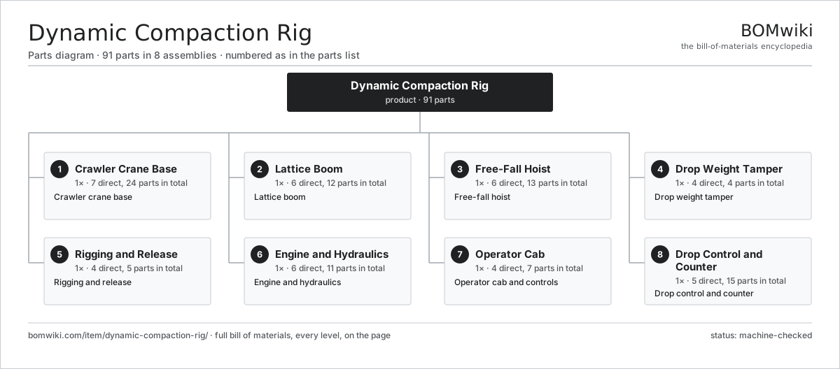
| # | Part | Qty | What it does |
|---|---|---|---|
| 1 | Crawler Crane Base 7 parts | 1× | Crawler crane base |
| 2 | Lattice Boom 6 parts | 1× | Lattice boom |
| 3 | Free-Fall Hoist 6 parts | 1× | Free-fall hoist |
| 4 | Drop Weight Tamper 4 parts | 1× | Drop weight tamper |
| 5 | Rigging and Release 4 parts | 1× | Rigging and release |
| 6 | Engine and Hydraulics 6 parts | 1× | Engine and hydraulics |
| 7 | Operator Cab 4 parts | 1× | Operator cab and controls |
| 8 | Drop Control and Counter 5 parts | 1× | Drop control and counter |
3D model
No 3D model yet. Have a CAD file of this? Add a 3D model — STL renders right on this page; STEP, FreeCAD, and OpenSCAD sources are welcome too (openly licensed, like all 3D models on BOMwiki).
Build & assembly graph
expand / collapse · shared sub-assemblies converge · links to related products · est. labourTap an assembly to expand/collapse · tap a part to open it · use “Open page” for any node · drag to pan, scroll to zoom.
Bill of materials for Dynamic Compaction Rig
8 top-level lines · 64 rows shown · 91 parts total · indented to 3 levels| # | Item / sub-assembly | Part no. | Qty/assy | Ext. qty | Parts | Type |
|---|---|---|---|---|---|---|
| 1 | Crawler Crane Base 7 parts | dynamic-compaction-rig-crawler-crane | 1× | 1 | 24 | assembly |
| 1.1 | Track Frame | dynamic-compaction-rig-track-frame | 2× | 2 | · | part |
| 1.2 | Track Chain | dynamic-compaction-rig-track-chain | 2× | 2 | · | part |
| 1.3 | Travel Motor 4 parts | dynamic-compaction-rig-track-motor | 2× | 2 | 8 | assembly |
| 1.3.1 | Gearbox Housing | gearbox-housing | 1× | 2 | · | part |
| 1.3.2 | Helical Gear Pair | gear-pair | 2× | 4 | · | part |
| 1.3.3 | Ball Bearing | ball-bearing | 3× | 6 | · | part |
| 1.3.4 | Oil Seal | oil-seal | 2× | 4 | · | part |
| 1.4 | Slew Ring | dynamic-compaction-rig-slew-ring | 1× | 1 | · | part |
| 1.5 | Counterweight | dynamic-compaction-rig-counterweight | 1× | 1 | · | part |
| 1.6 | Car Body | dynamic-compaction-rig-car-body | 1× | 1 | · | part |
| 1.7 | Fastener Set | fastener-set | 1× | 1 | · | part |
| 2 | Lattice Boom 6 parts | dynamic-compaction-rig-boom | 1× | 1 | 12 | assembly |
| 2.1 | Boom Butt | dynamic-compaction-rig-boom-butt | 1× | 1 | · | part |
| 2.2 | Boom Insert | dynamic-compaction-rig-boom-insert | 3× | 3 | · | part |
| 2.3 | Boom Tip | dynamic-compaction-rig-boom-tip | 1× | 1 | · | part |
| 2.4 | Head Sheave | dynamic-compaction-rig-boom-sheave | 2× | 2 | · | part |
| 2.5 | Pendant Bar | dynamic-compaction-rig-pendant | 4× | 4 | · | part |
| 2.6 | Fastener Set | fastener-set | 1× | 1 | · | part |
| 3 | Free-Fall Hoist 6 parts | dynamic-compaction-rig-hoist | 1× | 1 | 13 | assembly |
| 3.1 | Hoist Drum | dynamic-compaction-rig-hoist-drum | 1× | 1 | · | part |
| 3.2 | Hoist Motor 3 parts | dynamic-compaction-rig-hoist-motor | 1× | 1 | 5 | assembly |
| 3.2.1 | Gearbox Housing | gearbox-housing | 1× | 1 | · | part |
| 3.2.2 | Helical Gear Pair | gear-pair | 2× | 2 | · | part |
| 3.2.3 | Ball Bearing | ball-bearing | 2× | 2 | · | part |
| 3.3 | Free-Fall Clutch | dynamic-compaction-rig-freefall-clutch | 1× | 1 | · | part |
| 3.4 | Drum Brake | dynamic-compaction-rig-hoist-brake | 1× | 1 | · | part |
| 3.5 | Hoist Rope | dynamic-compaction-rig-hoist-rope | 1× | 1 | · | part |
| 3.6 | Ball Bearing | ball-bearing | 4× | 4 | · | part |
| 4 | Drop Weight Tamper 4 parts | dynamic-compaction-rig-tamper | 1× | 1 | 4 | assembly |
| 4.1 | Weight Body | dynamic-compaction-rig-weight-body | 1× | 1 | · | part |
| 4.2 | Vent Hole | dynamic-compaction-rig-vent-hole | 1× | 1 | · | part |
| 4.3 | Lifting Eye | dynamic-compaction-rig-lift-eye | 1× | 1 | · | part |
| 4.4 | Impact Plate | dynamic-compaction-rig-impact-plate | 1× | 1 | · | part |
| 5 | Rigging and Release 4 parts | dynamic-compaction-rig-rigging | 1× | 1 | 5 | assembly |
| 5.1 | Lower Block | dynamic-compaction-rig-lower-block | 1× | 1 | · | part |
| 5.2 | Release Hook | dynamic-compaction-rig-release-hook | 1× | 1 | · | part |
| 5.3 | Anti-Spin Swivel | dynamic-compaction-rig-swivel | 1× | 1 | · | part |
| 5.4 | Lift Sling | dynamic-compaction-rig-sling | 2× | 2 | · | part |
| 6 | Engine and Hydraulics 6 parts | dynamic-compaction-rig-powerpack | 1× | 1 | 11 | assembly |
| 6.1 | Diesel Engine 3 parts | dynamic-compaction-rig-diesel-engine | 1× | 1 | 5 | assembly |
| 6.1.1 | Engine Block | dynamic-compaction-rig-engine-block | 1× | 1 | · | part |
| 6.1.2 | Cooling Package | dynamic-compaction-rig-radiator | 1× | 1 | · | part |
| 6.1.3 | Oil Seal | oil-seal | 3× | 3 | · | part |
| 6.2 | Main Pump | dynamic-compaction-rig-main-pump | 2× | 2 | · | part |
| 6.3 | Valve Block | dynamic-compaction-rig-valve-block | 1× | 1 | · | part |
| 6.4 | Reservoir | dynamic-compaction-rig-reservoir | 1× | 1 | · | part |
| 6.5 | Oil Cooler | dynamic-compaction-rig-oil-cooler | 1× | 1 | · | part |
| 6.6 | O-Ring Set | oring-set | 1× | 1 | · | part |
| 7 | Operator Cab 4 parts | dynamic-compaction-rig-cab | 1× | 1 | 7 | assembly |
| 7.1 | Cab Shell | dynamic-compaction-rig-cab-shell | 1× | 1 | · | part |
| 7.2 | Operator Seat | dynamic-compaction-rig-seat | 1× | 1 | · | part |
| 7.3 | Control Lever | dynamic-compaction-rig-lever | 4× | 4 | · | part |
| 7.4 | LCD Panel | lcd-panel | 1× | 1 | · | part |
| 8 | Drop Control and Counter 5 parts | dynamic-compaction-rig-control | 1× | 1 | 15 | assembly |
| 8.1 | Drop Controller 4 parts | dynamic-compaction-rig-controller | 1× | 1 | 6 | assembly |
| 8.1.1 | Bare PCB | pcb-bare | 1× | 1 | · | part |
| 8.1.2 | Microcontroller | mcu | 1× | 1 | · | part |
| 8.1.3 | SMD Passive (R/C/L) | smd-passives | 1× | 1 | · | part |
| 8.1.4 | Relay | relay | 3× | 3 | · | part |
| 8.2 | Blow Counter | dynamic-compaction-rig-drop-counter | 1× | 1 | · | part |
| 8.3 | Height Encoder | dynamic-compaction-rig-height-encoder | 1× | 1 | · | part |
| 8.4 | Wire Bundle | wire-bundle | 1× | 1 | · | part |
| 8.5 | Connector | connector | 6× | 6 | · | part |
Related products
same domain, ranked by shared parts All-Terrain Mobile Crane
594 parts · shares 9 with this page
All-Terrain Mobile Crane
594 parts · shares 9 with this page
 Asphalt Milling Machine
1,134 parts · shares 9 with this page
Asphalt Milling Machine
1,134 parts · shares 9 with this page
 Asphalt Recycler
226 parts · shares 9 with this page
Bridge Form Traveler
405 parts · shares 9 with this page
Asphalt Recycler
226 parts · shares 9 with this page
Bridge Form Traveler
405 parts · shares 9 with this page
 Bridge Girder Launching Gantry
1,542 parts · shares 9 with this page
Bridge Girder Launching Gantry
1,542 parts · shares 9 with this page
 CFA Piling Rig
611 parts · shares 9 with this page
CFA Piling Rig
611 parts · shares 9 with this page
Sourcing: possible vendors
Prices, MOQ, and lead times are algorithmic estimates, not quotes, and not claims about these companies. Company mappings are curated by keyword; est. price band $15k–$2M. How estimates work| Vendor | HQ | Specialty | MOQ | Lead time |
|---|---|---|---|---|
| caterpillar.com ↗ | Irving, US | Construction & mining equipment | made to order | 16–28 wks |
|
🇯🇵Komatsu
komatsu.com ↗
|
Tokyo, JP | Construction & mining equipment | made to order | 16–28 wks |
|
🇸🇪Volvo CE
volvoce.com ↗
|
Gothenburg, SE | Construction equipment | made to order | 16–28 wks |
|
🇨🇭Liebherr
liebherr.com ↗
|
Bulle, CH | Cranes & heavy equipment | made to order | 16–28 wks |
|
🇨🇳XCMG
xcmg.com ↗
|
Xuzhou, CN | Construction machinery | made to order | 16–28 wks |
934-word article