Excavator
ProductAlso known as: Caterpillar 320, Komatsu PC200, hydraulic excavator, digger, JCB, CAT excavator, backhoe
Overview
The excavator is a hydraulic crawler machine used for digging, trenching, lifting and material handling. It belongs to the 20–30 tonne class, the most common size for general earthmoving on construction and utility sites. The machine consists of a tracked Undercarriage that carries a rotating Upper Structure, on which the engine, hydraulics, counterweight and cab are mounted. The Work Equipment mounts to the front of the upper structure and reaches out ahead of the machine to dig.
All working motions are powered hydraulically. A Diesel Engine drives the pumps in the Hydraulic System, which in turn drive the cylinders, the travel motors and the swing motor. There is no mechanical drivetrain to the tracks or the tools: the only rotating mechanical link from the engine is the pump driveline. This layout lets a single engine supply continuously variable speed and force to every function, and it lets the machine rotate the entire upper body through a full circle while the tracks stay put.
Diesel engine
The prime mover is a turbocharged, water-cooled inline-6 Diesel Engine in the 120–160 kW range. The Engine Block holds six wet Cylinder Liner bores closed by a single Cylinder Head. Each bore carries a Piston & Connecting Rod comprising a Piston, its Piston Ring Set and a Connecting Rod, all running on a forged Crankshaft.
Fuel is metered by a common-rail Fuel System: a High-Pressure Injection Pump raises pressure into the Fuel Rail, and six Common-Rail Injector units spray each cylinder under electronic control, with a Fuel Filter protecting the high-pressure parts. A Turbocharger uses exhaust energy at its Turbine Wheel to drive a Compressor Wheel in the Turbo Housing, packing more air into the cylinders for higher output. Exhaust then passes through a Diesel Particulate Filter to trap soot. Cooling is handled by a Radiator and a belt-driven Coolant Pump.
Hydraulic system
The Hydraulic System is an open-centre design built around two Main Hydraulic Pump units. Each is a variable-displacement axial-piston pump: a Pump Rotating Group runs against an adjustable Swash Plate whose angle, set by the Pump Regulator, varies the flow on demand. A separate Pilot Gear Pump supplies low-pressure oil for the control circuit. System pressure reaches about 34.3 MPa.
Pump flow feeds the Main Control Valve, a Spool Block Casting holding eight Control Spool elements that route oil to each actuator, with four Relief Valve cartridges capping circuit pressure. Oil is stored in the Hydraulic Tank, drawn through a Suction Strainer in the Tank Shell and vented by a Tank Breather. On return it passes a Hydraulic Return Filter and is cooled by the Hydraulic Oil Cooler before re-entering the tank.
Undercarriage
The Undercarriage is a welded base with two driven crawler tracks. Each side has a Track Frame carrying a Track Chain, which is an endless loop of 46-link sets built from Track Link plates, ground-engaging Steel Track Shoe pads, and Track Pin and Track Bushing joints. A driven Drive Sprocket meshes with the bushings at the rear, a Front Idler guides the chain at the front, and the load is spread by a row of Track Roller units below and a Carrier Roller above on each side. A Track Tension Cylinder, using a Hydraulic Cylinder Tube and Cylinder Piston Rod, pushes the idler forward against a grease charge to keep the chain taut.
Each track is driven by a Final Drive at the sprocket. It pairs a Travel Motor, an axial-piston hydraulic motor, with a multi-stage planetary Helical Gear Pair reduction inside a Gearbox Housing. The two motors give independent left and right drive, so the machine steers by running its tracks at different speeds or in opposite directions, and it can counter-rotate in place.
Upper structure and swing
The Upper Structure is the slewing platform. Its welded Rotating Frame sits on a Swing Bearing (Slew Ring), a large slew ring whose inner race is fixed to the undercarriage. A Swing Drive rotates the platform: a Swing Motor turns through a Helical Gear Pair reduction in a Gearbox Housing, and its output pinion meshes with the toothed slew ring. A cast Counterweight is bolted to the rear of the frame to balance the load at the bucket and keep the machine stable through its working arc. Swing speed is typically around 11 rev/min.
Work equipment
The Work Equipment is the digging linkage at the front. A Boom pivots at the frame and is raised by two Boom Cylinder actuators. An Arm (Stick), also called the stick, hinges at the boom tip and is driven by a single Arm Cylinder. At the end of the arm a Bucket is curled by a Bucket Cylinder acting through a Bucket Linkage, an H-and-I link arrangement using a H-Link and two I-Link members on Pivot Pin and Pivot Bushing joints. The linkage multiplies cylinder force into high breakout torque at the teeth. The bucket itself is a welded Bucket Shell fitted with replaceable Bucket Tooth points. Every cylinder shares the same construction: a Hydraulic Cylinder Tube, a chromed Cylinder Piston Rod, and seals.
Cab and electrical
The operator works from a Operator Cab built on a ROPS Cab Frame that protects against rollover. The operator sits in a suspension Seat Assembly and commands the machine through two Pilot Joystick levers; each joystick has a Joystick Grip, a Pilot Control Valve that meters pilot oil to shift the control spools, and several Control Switch. A Cab Monitor shows engine and hydraulic readings, and a Cab HVAC Unit unit with its HVAC Blower and Cab Air Filter keeps the cab climate-controlled.
The Electrical System system runs at 24 V from two series 12 V Battery units. An Alternator, with its Rectifier Bridge, charges the batteries while the engine runs. A Machine Controller (ECU) machine ECU manages engine and pump settings, fed through a Wire Bundle harness with a Fuse Box and bank of Relay units, and four LED Work Light LED lamps illuminate the work area.
Excavator parts and their functions
7 top-level parts · 11,218 parts in total · full bill of materials below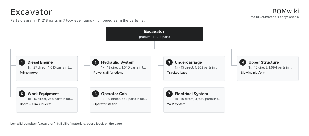
| # | Part | Qty | What it does |
|---|---|---|---|
| 1 | Diesel Engine 27 parts | 1× | Prime mover |
| 2 | Hydraulic System 19 parts | 1× | Powers all functions |
| 3 | Undercarriage 15 parts | 1× | Tracked base |
| 4 | Upper Structure 15 parts | 1× | Slewing platform |
| 5 | Work Equipment 16 parts | 1× | Boom + arm + bucket |
| 6 | Operator Cab 19 parts | 1× | Operator station |
| 7 | Electrical System 16 parts | 1× | 24 V system |
Diagrams & photos


3D model
No 3D model yet. Have a CAD file of this? Add a 3D model. STL renders right on this page; STEP, FreeCAD, and OpenSCAD sources are welcome too (openly licensed, like all 3D models on BOMwiki).
Build & assembly graph
expand / collapse · shared sub-assemblies converge · links to related products · est. labourTap an assembly to expand/collapse · tap a part to open it · use “Open page” for any node · drag to pan, scroll to zoom.
Bill of materials for Excavator
7 top-level lines · 227 rows shown · 11,218 parts total · indented to 3 levels| # | Item / sub-assembly | Part no. | Qty/assy | Ext. qty | Parts | Type |
|---|---|---|---|---|---|---|
| 1 | Diesel Engine 27 parts | excavator-diesel-engine | 1× | 1 | 1,015 | assembly |
| 1.1 | Engine Block 4 parts | excavator-engine-block | 1× | 1 | 9 | assembly |
| 1.1.1 | Cylinder Liner | excavator-cylinder-liner | 6× | 6 | · | part |
| 1.1.2 | Cylinder Head | excavator-cylinder-head | 1× | 1 | · | part |
| 1.1.3 | O-Ring Set | oring-set | 1× | 1 | · | part |
| 1.1.4 | Fastener Set | fastener-set | 1× | 1 | · | part |
| 1.2 | Piston & Connecting Rod 4 parts | excavator-piston-set | 6× | 6 | 4 | assembly |
| 1.2.1 | Piston | excavator-piston | 1× | 6 | · | part |
| 1.2.2 | Piston Ring Set | excavator-piston-ring-set | 1× | 6 | · | part |
| 1.2.3 | Connecting Rod | excavator-conrod | 1× | 6 | · | part |
| 1.2.4 | Ball Bearing | ball-bearing | 1× | 6 | · | part |
| 1.3 | Crankshaft | excavator-crankshaft | 1× | 1 | · | part |
| 1.4 | Turbocharger 5 parts | excavator-turbocharger | 1× | 1 | 7 | assembly |
| 1.4.1 | Turbine Wheel | excavator-turbine-wheel | 1× | 1 | · | part |
| 1.4.2 | Compressor Wheel | excavator-compressor-wheel | 1× | 1 | · | part |
| 1.4.3 | Turbo Housing | excavator-turbo-housing | 1× | 1 | · | part |
| 1.4.4 | Ball Bearing | ball-bearing | 2× | 2 | · | part |
| 1.4.5 | Oil Seal | oil-seal | 2× | 2 | · | part |
| 1.5 | Fuel System 4 parts | excavator-fuel-system | 1× | 1 | 9 | assembly |
| 1.5.1 | Common-Rail Injector | excavator-fuel-injector | 6× | 6 | · | part |
| 1.5.2 | High-Pressure Injection Pump | excavator-injection-pump | 1× | 1 | · | part |
| 1.5.3 | Fuel Filter | excavator-fuel-filter | 1× | 1 | · | part |
| 1.5.4 | Fuel Rail | excavator-fuel-rail | 1× | 1 | · | part |
| 1.6 | Radiator | radiator | 1× | 1 | · | part |
| 1.7 | Coolant Pump | coolant-pump | 1× | 1 | · | part |
| 1.8 | Diesel Particulate Filter | excavator-dpf | 1× | 1 | · | part |
| 1.9 | Piston Ring | excavator-piston-ring | 18× | 18 | · | part |
| 1.10 | Bearing Shell | excavator-bearing-shell | 26× | 26 | · | part |
| 1.11 | Poppet Valve | excavator-valve | 24× | 24 | · | part |
| 1.12 | Valve Spring | excavator-valve-spring | 24× | 24 | · | part |
| 1.13 | Valve Train Component | excavator-valve-train-part | 24× | 24 | · | part |
| 1.14 | Camshaft | excavator-camshaft | 1× | 1 | · | part |
| 1.15 | Flywheel & Housing | excavator-flywheel | 1× | 1 | · | part |
| 1.16 | Charge Air Cooler | excavator-intercooler | 1× | 1 | · | part |
| 1.17 | Air Cleaner Assembly | excavator-air-cleaner | 1× | 1 | · | part |
| 1.18 | Exhaust Pipe & Muffler | excavator-exhaust-pipe | 3× | 3 | · | part |
| 1.19 | Engine Mount | excavator-engine-mount | 4× | 4 | · | part |
| 1.20 | Cooling Fan & Drive | excavator-fan-drive | 1× | 1 | · | part |
| 1.21 | Engine Sensor | excavator-engine-sensor | 20× | 20 | · | part |
| 1.22 | Engine Gasket & Seal | excavator-engine-gasket | 40× | 40 | · | part |
| 1.23 | Engine Bolt & Stud | excavator-engine-bolt | 620× | 620 | · | part |
| 1.24 | Connector | connector | 48× | 48 | · | part |
| 1.25 | Oil Seal | oil-seal | 6× | 6 | · | part |
| 1.26 | Hex Bolt | excavator-hex-bolt | 60× | 60 | · | part |
| 1.27 | Hex Nut | excavator-hex-nut | 40× | 40 | · | part |
| 2 | Hydraulic System 19 parts | excavator-hydraulic-system | 1× | 1 | 1,540 | assembly |
| 2.1 | Main Hydraulic Pump 6 parts | excavator-main-hydraulic-pump | 2× | 2 | 7 | assembly |
| 2.1.1 | Pump Rotating Group | excavator-pump-rotating-group | 1× | 2 | · | part |
| 2.1.2 | Swash Plate | excavator-swash-plate | 1× | 2 | · | part |
| 2.1.3 | Pump Regulator | excavator-pump-regulator | 1× | 2 | · | part |
| 2.1.4 | Ball Bearing | ball-bearing | 2× | 4 | · | part |
| 2.1.5 | Oil Seal | oil-seal | 1× | 2 | · | part |
| 2.1.6 | O-Ring Set | oring-set | 1× | 2 | · | part |
| 2.2 | Pilot Gear Pump | excavator-pilot-pump | 1× | 1 | · | part |
| 2.3 | Main Control Valve 4 parts | excavator-main-control-valve | 1× | 1 | 14 | assembly |
| 2.3.1 | Spool Block Casting | excavator-spool-block | 1× | 1 | · | part |
| 2.3.2 | Control Spool | excavator-control-spool | 8× | 8 | · | part |
| 2.3.3 | Relief Valve | excavator-relief-valve | 4× | 4 | · | part |
| 2.3.4 | O-Ring Set | oring-set | 1× | 1 | · | part |
| 2.4 | Hydraulic Tank 3 parts | excavator-hydraulic-tank | 1× | 1 | 3 | assembly |
| 2.4.1 | Tank Shell | excavator-tank-shell | 1× | 1 | · | part |
| 2.4.2 | Suction Strainer | excavator-suction-strainer | 1× | 1 | · | part |
| 2.4.3 | Tank Breather | excavator-breather | 1× | 1 | · | part |
| 2.5 | Hydraulic Oil Cooler | excavator-oil-cooler | 1× | 1 | · | part |
| 2.6 | Hydraulic Return Filter | excavator-hydraulic-filter | 2× | 2 | · | part |
| 2.7 | Hydraulic Hose Assembly | excavator-hydraulic-hose | 130× | 130 | · | part |
| 2.8 | Hydraulic Fitting | excavator-hose-fitting | 280× | 280 | · | part |
| 2.9 | Hydraulic Steel Tube | excavator-hydraulic-tube | 44× | 44 | · | part |
| 2.10 | Pilot Circuit Valve | excavator-pilot-circuit-valve | 10× | 10 | · | part |
| 2.11 | Solenoid Valve | excavator-solenoid-valve | 10× | 10 | · | part |
| 2.12 | Hydraulic Accumulator | excavator-accumulator | 2× | 2 | · | part |
| 2.13 | Center Swivel Joint | excavator-center-joint | 1× | 1 | · | part |
| 2.14 | Pressure Sensor | pressure-sensor | 8× | 8 | · | part |
| 2.15 | O-Ring Set | oring-set | 40× | 40 | · | part |
| 2.16 | Hex Bolt | excavator-hex-bolt | 360× | 360 | · | part |
| 2.17 | Hex Nut | excavator-hex-nut | 200× | 200 | · | part |
| 2.18 | Washer | excavator-washer | 200× | 200 | · | part |
| 2.19 | Cable Tie & Clamp | excavator-cable-tie | 220× | 220 | · | part |
| 3 | Undercarriage 15 parts | excavator-undercarriage | 1× | 1 | 1,362 | assembly |
| 3.1 | Track Frame | excavator-track-frame | 2× | 2 | · | part |
| 3.2 | Track Chain 4 parts | excavator-track-chain | 2× | 2 | 184 | assembly |
| 3.2.1 | Track Link | excavator-track-link | 46× | 92 | · | part |
| 3.2.2 | Steel Track Shoe | excavator-track-shoe | 46× | 92 | · | part |
| 3.2.3 | Track Pin | excavator-track-pin | 46× | 92 | · | part |
| 3.2.4 | Track Bushing | excavator-track-bushing | 46× | 92 | · | part |
| 3.3 | Drive Sprocket | excavator-sprocket | 2× | 2 | · | part |
| 3.4 | Front Idler | excavator-idler | 2× | 2 | · | part |
| 3.5 | Track Roller | excavator-track-roller | 14× | 14 | · | part |
| 3.6 | Carrier Roller | excavator-carrier-roller | 4× | 4 | · | part |
| 3.7 | Track Tension Cylinder 4 parts | excavator-track-tension-cylinder | 2× | 2 | 5 | assembly |
| 3.7.1 | Hydraulic Cylinder Tube | excavator-cylinder-tube | 1× | 2 | · | part |
| 3.7.2 | Cylinder Piston Rod | excavator-cylinder-piston-rod | 1× | 2 | · | part |
| 3.7.3 | Oil Seal | oil-seal | 2× | 4 | · | part |
| 3.7.4 | O-Ring Set | oring-set | 1× | 2 | · | part |
| 3.8 | Final Drive 5 parts | excavator-final-drive | 2× | 2 | 10 | assembly |
| 3.8.1 | Travel Motor | excavator-travel-motor | 1× | 2 | · | part |
| 3.8.2 | Helical Gear Pair | gear-pair | 3× | 6 | · | part |
| 3.8.3 | Gearbox Housing | gearbox-housing | 1× | 2 | · | part |
| 3.8.4 | Oil Seal | oil-seal | 2× | 4 | · | part |
| 3.8.5 | Ball Bearing | ball-bearing | 3× | 6 | · | part |
| 3.9 | Track Shoe Bolt & Nut | excavator-track-bolt | 400× | 400 | · | part |
| 3.10 | Roller Mounting Bolt | excavator-roller-bolt | 144× | 144 | · | part |
| 3.11 | Track Guard | excavator-track-guard | 4× | 4 | · | part |
| 3.12 | Grease Fitting | excavator-grease-fitting | 24× | 24 | · | part |
| 3.13 | Final Drive Bolt | excavator-final-drive-bolt | 48× | 48 | · | part |
| 3.14 | Hex Bolt | excavator-hex-bolt | 200× | 200 | · | part |
| 3.15 | Hex Nut | excavator-hex-nut | 120× | 120 | · | part |
| 4 | Upper Structure 15 parts | excavator-upper-structure | 1× | 1 | 1,694 | assembly |
| 4.1 | Rotating Frame | excavator-rotating-frame | 1× | 1 | · | part |
| 4.2 | Swing Bearing (Slew Ring) | excavator-swing-bearing | 1× | 1 | · | part |
| 4.3 | Swing Drive 5 parts | excavator-swing-drive | 1× | 1 | 7 | assembly |
| 4.3.1 | Swing Motor | excavator-swing-motor | 1× | 1 | · | part |
| 4.3.2 | Helical Gear Pair | gear-pair | 2× | 2 | · | part |
| 4.3.3 | Gearbox Housing | gearbox-housing | 1× | 1 | · | part |
| 4.3.4 | Oil Seal | oil-seal | 1× | 1 | · | part |
| 4.3.5 | Ball Bearing | ball-bearing | 2× | 2 | · | part |
| 4.4 | Counterweight | excavator-counterweight | 1× | 1 | · | part |
| 4.5 | Slew Ring Bolt | excavator-swing-bearing-bolt | 72× | 72 | · | part |
| 4.6 | Cover & Hood Panel | excavator-cover-panel | 14× | 14 | · | part |
| 4.7 | Hinge & Latch | excavator-hinge-latch | 36× | 36 | · | part |
| 4.8 | Handrail & Step | excavator-handrail | 8× | 8 | · | part |
| 4.9 | Mirror | excavator-mirror | 3× | 3 | · | part |
| 4.10 | Camera | excavator-camera | 2× | 2 | · | part |
| 4.11 | Battery Box & Toolbox | excavator-battery-box | 1× | 1 | · | part |
| 4.12 | Counterweight Bolt | excavator-counterweight-bolt | 8× | 8 | · | part |
| 4.13 | Hex Bolt | excavator-hex-bolt | 700× | 700 | · | part |
| 4.14 | Hex Nut | excavator-hex-nut | 420× | 420 | · | part |
| 4.15 | Washer | excavator-washer | 420× | 420 | · | part |
| 5 | Work Equipment 16 parts | excavator-work-equipment | 1× | 1 | 264 | assembly |
| 5.1 | Boom | excavator-boom | 1× | 1 | · | part |
| 5.2 | Boom Cylinder 4 parts | excavator-boom-cylinder | 2× | 2 | 5 | assembly |
| 5.2.1 | Hydraulic Cylinder Tube | excavator-cylinder-tube | 1× | 2 | · | part |
| 5.2.2 | Cylinder Piston Rod | excavator-cylinder-piston-rod | 1× | 2 | · | part |
| 5.2.3 | Oil Seal | oil-seal | 2× | 4 | · | part |
| 5.2.4 | O-Ring Set | oring-set | 1× | 2 | · | part |
| 5.3 | Arm (Stick) | excavator-arm | 1× | 1 | · | part |
| 5.4 | Arm Cylinder 4 parts | excavator-arm-cylinder | 1× | 1 | 5 | assembly |
| 5.4.1 | Hydraulic Cylinder Tube | excavator-cylinder-tube | 1× | 1 | · | part |
| 5.4.2 | Cylinder Piston Rod | excavator-cylinder-piston-rod | 1× | 1 | · | part |
| 5.4.3 | Oil Seal | oil-seal | 2× | 2 | · | part |
| 5.4.4 | O-Ring Set | oring-set | 1× | 1 | · | part |
| 5.5 | Bucket 3 parts | excavator-bucket | 1× | 1 | 7 | assembly |
| 5.5.1 | Bucket Shell | excavator-bucket-shell | 1× | 1 | · | part |
| 5.5.2 | Bucket Tooth | excavator-bucket-tooth | 5× | 5 | · | part |
| 5.5.3 | Fastener Set | fastener-set | 1× | 1 | · | part |
| 5.6 | Bucket Cylinder 4 parts | excavator-bucket-cylinder | 1× | 1 | 5 | assembly |
| 5.6.1 | Hydraulic Cylinder Tube | excavator-cylinder-tube | 1× | 1 | · | part |
| 5.6.2 | Cylinder Piston Rod | excavator-cylinder-piston-rod | 1× | 1 | · | part |
| 5.6.3 | Oil Seal | oil-seal | 2× | 2 | · | part |
| 5.6.4 | O-Ring Set | oring-set | 1× | 1 | · | part |
| 5.7 | Bucket Linkage 4 parts | excavator-bucket-linkage | 1× | 1 | 11 | assembly |
| 5.7.1 | H-Link | excavator-link-h | 1× | 1 | · | part |
| 5.7.2 | I-Link | excavator-link-i | 2× | 2 | · | part |
| 5.7.3 | Pivot Pin | excavator-pivot-pin | 4× | 4 | · | part |
| 5.7.4 | Pivot Bushing | excavator-pivot-bushing | 4× | 4 | · | part |
| 5.8 | Pivot Pin | excavator-pivot-pin | 10× | 10 | · | part |
| 5.9 | Pin Bushing | excavator-bushing | 28× | 28 | · | part |
| 5.10 | Shim & Thrust Ring | excavator-shim | 40× | 40 | · | part |
| 5.11 | Pin Retainer | excavator-pin-retainer | 14× | 14 | · | part |
| 5.12 | Grease Line | excavator-grease-line | 14× | 14 | · | part |
| 5.13 | Grease Fitting | excavator-grease-fitting | 20× | 20 | · | part |
| 5.14 | Hose Guard & Clamp | excavator-hose-guard | 12× | 12 | · | part |
| 5.15 | Cylinder Seal Kit | excavator-hydraulic-seal-kit | 6× | 6 | · | part |
| 5.16 | Hex Bolt | excavator-hex-bolt | 80× | 80 | · | part |
| 6 | Operator Cab 19 parts | excavator-cab | 1× | 1 | 663 | assembly |
| 6.1 | ROPS Cab Frame | excavator-rops-frame | 1× | 1 | · | part |
| 6.2 | Seat Assembly 5 parts | seat-assembly | 1× | 1 | 7 | assembly |
| 6.2.1 | Seat Frame | seat-frame | 1× | 1 | · | part |
| 6.2.2 | Seat Foam | seat-foam | 2× | 2 | · | part |
| 6.2.3 | Seat Cover | seat-cover | 1× | 1 | · | part |
| 6.2.4 | Seat Motor | seat-motor | 2× | 2 | · | part |
| 6.2.5 | Seat Heater Mat | seat-heater | 1× | 1 | · | part |
| 6.3 | Pilot Joystick 3 parts | excavator-joystick | 2× | 2 | 6 | assembly |
| 6.3.1 | Joystick Grip | excavator-joystick-grip | 1× | 2 | · | part |
| 6.3.2 | Pilot Control Valve | excavator-pilot-valve | 1× | 2 | · | part |
| 6.3.3 | Control Switch | excavator-control-switches | 4× | 8 | · | part |
| 6.4 | Cab Monitor 4 parts | excavator-monitor | 1× | 1 | 7 | assembly |
| 6.4.1 | Bare PCB | pcb-bare | 1× | 1 | · | part |
| 6.4.2 | Microcontroller | mcu | 1× | 1 | · | part |
| 6.4.3 | LCD Panel | lcd-panel | 1× | 1 | · | part |
| 6.4.4 | Connector | connector | 4× | 4 | · | part |
| 6.5 | Cab HVAC Unit 3 parts | excavator-hvac | 1× | 1 | 3 | assembly |
| 6.5.1 | HVAC Blower | excavator-blower | 1× | 1 | · | part |
| 6.5.2 | Heating Element | heating-element | 1× | 1 | · | part |
| 6.5.3 | Cab Air Filter | excavator-cab-filter | 1× | 1 | · | part |
| 6.6 | Cab Glass | excavator-cab-glass | 6× | 6 | · | part |
| 6.7 | Cab Door | excavator-cab-door | 1× | 1 | · | part |
| 6.8 | Wiper & Washer | excavator-wiper | 2× | 2 | · | part |
| 6.9 | Cab Mount | excavator-cab-mount | 4× | 4 | · | part |
| 6.10 | Cab Interior Trim | excavator-interior-trim | 14× | 14 | · | part |
| 6.11 | Travel Pedal & Lever | excavator-travel-pedal | 2× | 2 | · | part |
| 6.12 | Switch | excavator-switch | 24× | 24 | · | part |
| 6.13 | HVAC Duct & Vent | excavator-hvac-duct | 6× | 6 | · | part |
| 6.14 | Seat Belt | excavator-seat-belt | 1× | 1 | · | part |
| 6.15 | Cab Radio | excavator-radio | 1× | 1 | · | part |
| 6.16 | Sound Insulation Pad | excavator-sound-insulation | 12× | 12 | · | part |
| 6.17 | Trim Clip | excavator-trim-clip | 220× | 220 | · | part |
| 6.18 | Hex Bolt | excavator-hex-bolt | 220× | 220 | · | part |
| 6.19 | Hex Nut | excavator-hex-nut | 120× | 120 | · | part |
| 7 | Electrical System 16 parts | excavator-electrical | 1× | 1 | 4,680 | assembly |
| 7.1 | 12 V Battery | lv-battery | 2× | 2 | · | part |
| 7.2 | Alternator 4 parts | excavator-alternator | 1× | 1 | 25 | assembly |
| 7.2.1 | Stator Assembly 3 parts + deeper › | stator-assembly | 1× | 1 | 3 | assembly |
| 7.2.2 | Rotor Assembly 4 parts + deeper › | rotor-assembly | 1× | 1 | 19 | assembly |
| 7.2.3 | Rectifier Bridge | excavator-rectifier | 1× | 1 | · | part |
| 7.2.4 | Ball Bearing | ball-bearing | 2× | 2 | · | part |
| 7.3 | Wire Bundle | wire-bundle | 1× | 1 | · | part |
| 7.4 | LED Work Light | excavator-work-light | 4× | 4 | · | part |
| 7.5 | Machine Controller (ECU) 3 parts | excavator-controller | 1× | 1 | 8 | assembly |
| 7.5.1 | Bare PCB | pcb-bare | 1× | 1 | · | part |
| 7.5.2 | Microcontroller | mcu | 1× | 1 | · | part |
| 7.5.3 | Connector | connector | 6× | 6 | · | part |
| 7.6 | Fuse Box | fuse-box | 1× | 1 | · | part |
| 7.7 | Relay | relay | 8× | 8 | · | part |
| 7.8 | Insulated Wire (cut length) | excavator-wire | 1200× | 1,200 | · | part |
| 7.9 | Crimp Terminal | excavator-crimp-terminal | 2400× | 2,400 | · | part |
| 7.10 | Connector | connector | 260× | 260 | · | part |
| 7.11 | Fuse | excavator-fuse | 40× | 40 | · | part |
| 7.12 | Machine Sensor | excavator-sensor | 30× | 30 | · | part |
| 7.13 | Beacon & Horn | excavator-beacon | 1× | 1 | · | part |
| 7.14 | Travel Alarm | excavator-travel-alarm | 1× | 1 | · | part |
| 7.15 | Electronic Control Unit 4 parts | ecu | 3× | 3 | 93 | assembly |
| 7.15.1 | Bare PCB | pcb-bare | 1× | 3 | · | part |
| 7.15.2 | Microcontroller | mcu | 1× | 3 | · | part |
| 7.15.3 | CAN Transceiver | can-transceiver | 1× | 3 | · | part |
| 7.15.4 | SMD Passive (R/C/L) | smd-passives | 90× | 270 | · | part |
| 7.16 | Cable Tie & Clamp | excavator-cable-tie | 420× | 420 | · | part |
Something wrong in this list? Report a problem with this BOM.
Related products
same domain, ranked by shared parts


Sourcing: possible vendors
Browse the supplier directory → Prices, MOQ, and lead times are algorithmic estimates, not quotes, and not claims about these companies. Company mappings are curated by keyword; est. price band $15k–$2M. How estimates work| Vendor | HQ | Specialty | MOQ | Lead time |
|---|---|---|---|---|
| caterpillar.com ↗ | Irving, US | Construction & mining equipment | made to order | 16–28 wks |
|
🇯🇵Komatsu
komatsu.com ↗
|
Tokyo, JP | Construction & mining equipment | made to order | 16–28 wks |
|
🇸🇪Volvo CE
volvoce.com ↗
|
Gothenburg, SE | Construction equipment | made to order | 16–28 wks |
|
🇨🇭Liebherr
liebherr.com ↗
|
Bulle, CH | Cranes & heavy equipment | made to order | 16–28 wks |
|
🇨🇳XCMG
xcmg.com ↗
|
Xuzhou, CN | Construction machinery | made to order | 16–28 wks |
1,073-word article