Sheet Pile Press
ProductOverview
A sheet pile press, also called a silent piler or press-in machine, installs interlocking steel sheet piles by pushing them into the ground with a static hydraulic force instead of hammering or vibrating them. The technique was commercialised in Japan and is often called the press-in method or the Giken-style press-in method after its best known maker. The machine grips piles that have already been driven, uses them as the reaction anchor, and then presses the next pile down beside them. Because there is no impact and no vibration, the press can work close to existing buildings, on soft urban ground, and at night without disturbing neighbours. Press-in force ranges from about 400 kN on small units to 2500 kN on the largest, and machine mass runs from roughly 5 t to 25 t.
The full machine is the Sheet Pile Press product, and it breaks into eight main subsystems: the Press-in Chuck Assembly, the Reaction Grip Clamp Set, the Main Press Cylinder Set, the Slide and Leader Frame, the Self-Walking Advance Mechanism, the Hydraulic Interface and Valving, the Control System, and the Lift Point Set.
How Press-in Works
The principle is reaction borrowed from already-installed piles. A conventional hammer or vibratory driver reacts against its own mass and gravity, which is why those methods are loud and shake the surrounding soil. The press instead clamps onto the three or four piles already in the ground through its Reaction Grip Clamp Set, and that grip gives it a fixed anchor far stronger than its own weight. With the reaction set, the Main Press Cylinder Set extend and drive the working pile straight down.
A single cycle runs in steps. The Press-in Chuck Assembly grips the head of the new pile through its Grip Jaw pair, each closed by a Jaw Clamp Cylinder at 200-350 bar to set a friction grip of 600-1200 kN. The two Press Cylinder units then push the pile down their full 800-1000 mm stroke. The chuck releases, the Slide Carriage rides back up the Leader Mast on its Linear Guide Rail rails, the chuck re-grips lower on the pile, and the cycle repeats until the pile reaches design depth. Pull-out reverses the same actuators to extract a pile when the wall is temporary.
Reaction and Self-Walking
The Reaction Grip Clamp Set are saddle clamps. Each Saddle Clamp straddles a driven pile through a cast Saddle Body and bites both flanges with a Clamp Grip Pad pair, closed by a Clamp Cylinder. A Clamp Spreader Beam ties the saddles so the reaction spreads across several piles rather than overloading one.
After a pile is fully pressed, the machine moves itself forward by one pile pitch using the Self-Walking Advance Mechanism. The Walk Lift Cylinder pair lifts the body clear of the last pile, the Lateral Slide Cylinder pushes it sideways along the Walking Slide Rail by exactly one pile pitch, and the machine resets its grip on the new lead pile. This leg-walk lets the press travel along the wall under its own power and stay perched on top of the piles it has installed, so it never needs working room on the ground beside the wall.
Hydraulics and Control
Oil comes from a separate diesel or electric power pack connected through the Quick Coupler fittings. Onboard, the Hydraulic Interface and Valving routes flow through a Valve Manifold Block manifold. A Pilot Selector Valve for each function lets the controller send oil to the press, clamp, rotate, or walk group in turn, and a Pressure Relief Valve caps the line at the 350 bar system limit. High-pressure High-Pressure Hose runs carry oil to each cylinder.
The Control System sequences the whole cycle. Its PLC Control Unit reads a Pressure Sensor on the press line, a Position Sensor on each stroke, and an Inclinometer that reports pile verticality, then drives the valve solenoids in order. The operator works from outside the machine with the cordless Remote Handset, which carries an LCD Panel showing press force and depth. Press-force feedback matters because the force needed to advance a pile is a direct reading of ground resistance, which the crew uses to confirm the pile has reached firm bearing.
Materials and Construction
The load path runs through forged and cast alloy steel. The Chuck Body and the Jaw Block are made from medium-carbon alloy steels such as 34CrMo4, and the gripping Serrated Jaw Insert plates are through-hardened tool steel at 55-60 HRC so their serrations bite the pile web without slipping. These inserts are the main wear item and are bolted in for quick replacement. The Cylinder Tube members are honed seamless tube, and every Piston Rod is hard-chrome plated and induction hardened to resist scoring in dirty site conditions. Seals throughout are standard O-Ring Set and Oil Seal items so field service is simple. The Main Structural Frame is a heavy welded steel weldment that carries every subsystem and sets the 5-25 t machine mass.
Variants and Use
Machines are sized by pile profile and press force. Small standard-section presses handle U and Z sheet piles for cofferdams, retaining walls, and flood defences in tight sites. Larger presses, and a related family that adds water jetting or augering at the chuck, install piles into stiff clay, dense sand, and even soft rock where plain press-in would stall. Tubular-pile versions press large-diameter steel pipe piles for deep foundations and quay walls.
Press-in is chosen where vibration is the limiting factor: alongside live railways, next to old masonry, over buried services, or in dense city centres. Because the Self-Walking Advance Mechanism keeps the machine on top of the wall, the press also works on narrow embankments and over water from the pile line itself, reached only by a service crane through the Lift Point Set. When a job finishes, the same machine can pull the piles back out for reuse, which makes the press-in method common for temporary works as well as permanent walls.
Sheet Pile Press parts and their functions
8 top-level parts · 403 parts in total · full bill of materials below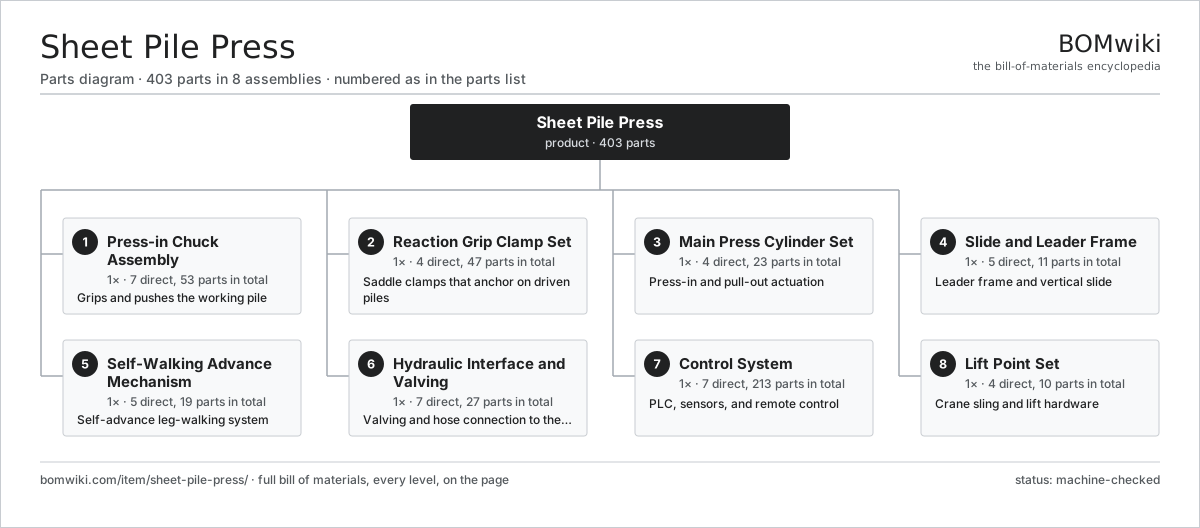
| # | Part | Qty | What it does |
|---|---|---|---|
| 1 | Press-in Chuck Assembly 7 parts | 1× | Grips and pushes the working pile |
| 2 | Reaction Grip Clamp Set 4 parts | 1× | Saddle clamps that anchor on driven piles |
| 3 | Main Press Cylinder Set 4 parts | 1× | Press-in and pull-out actuation |
| 4 | Slide and Leader Frame 5 parts | 1× | Leader frame and vertical slide |
| 5 | Self-Walking Advance Mechanism 5 parts | 1× | Self-advance leg-walking system |
| 6 | Hydraulic Interface and Valving 7 parts | 1× | Valving and hose connection to the power unit |
| 7 | Control System 7 parts | 1× | PLC, sensors, and remote control |
| 8 | Lift Point Set 4 parts | 1× | Crane sling and lift hardware |
3D model
No 3D model yet. Have a CAD file of this? Add a 3D model — STL renders right on this page; STEP, FreeCAD, and OpenSCAD sources are welcome too (openly licensed, like all 3D models on BOMwiki).
Build & assembly graph
expand / collapse · shared sub-assemblies converge · links to related products · est. labourTap an assembly to expand/collapse · tap a part to open it · use “Open page” for any node · drag to pan, scroll to zoom.
Bill of materials for Sheet Pile Press
8 top-level lines · 95 rows shown · 403 parts total · indented to 3 levels| # | Item / sub-assembly | Part no. | Qty/assy | Ext. qty | Parts | Type |
|---|---|---|---|---|---|---|
| 1 | Press-in Chuck Assembly 7 parts | sheet-pile-press-pressin-chuck | 1× | 1 | 53 | assembly |
| 1.1 | Chuck Body | sheet-pile-press-chuck-body | 1× | 1 | · | part |
| 1.2 | Grip Jaw 2 parts | sheet-pile-press-chuck-jaw | 2× | 2 | 3 | assembly |
| 1.2.1 | Jaw Block | sheet-pile-press-jaw-block | 1× | 2 | · | part |
| 1.2.2 | Serrated Jaw Insert | sheet-pile-press-jaw-insert | 2× | 4 | · | part |
| 1.3 | Jaw Clamp Cylinder 4 parts | sheet-pile-press-chuck-cylinder | 2× | 2 | 5 | assembly |
| 1.3.1 | Cylinder Tube | sheet-pile-press-cylinder-tube | 1× | 2 | · | part |
| 1.3.2 | Piston Rod | sheet-pile-press-piston-rod | 1× | 2 | · | part |
| 1.3.3 | O-Ring Set | oring-set | 2× | 4 | · | part |
| 1.3.4 | Oil Seal | oil-seal | 1× | 2 | · | part |
| 1.4 | Chuck Rotator 4 parts | sheet-pile-press-chuck-rotator | 1× | 1 | 27 | assembly |
| 1.4.1 | Slewing Ring Bearing | sheet-pile-press-slew-bearing | 1× | 1 | · | part |
| 1.4.2 | Helical Gear Pair | gear-pair | 1× | 1 | · | part |
| 1.4.3 | Servo Motor 4 parts + deeper › | servo-motor | 1× | 1 | 24 | assembly |
| 1.4.4 | Fastener Set | fastener-set | 1× | 1 | · | part |
| 1.5 | Serrated Jaw Insert | sheet-pile-press-jaw-insert | 4× | 4 | · | part |
| 1.6 | O-Ring Set | oring-set | 4× | 4 | · | part |
| 1.7 | Fastener Set | fastener-set | 1× | 1 | · | part |
| 2 | Reaction Grip Clamp Set 4 parts | sheet-pile-press-reaction-clamps | 1× | 1 | 47 | assembly |
| 2.1 | Saddle Clamp 4 parts | sheet-pile-press-saddle-clamp | 3× | 3 | 10 | assembly |
| 2.1.1 | Saddle Body | sheet-pile-press-saddle-body | 1× | 3 | · | part |
| 2.1.2 | Clamp Grip Pad | sheet-pile-press-clamp-pad | 2× | 6 | · | part |
| 2.1.3 | Clamp Cylinder 4 parts + deeper › | sheet-pile-press-clamp-cylinder | 1× | 3 | 5 | assembly |
| 2.1.4 | O-Ring Set | oring-set | 2× | 6 | · | part |
| 2.2 | Clamp Spreader Beam | sheet-pile-press-clamp-beam | 1× | 1 | · | part |
| 2.3 | Clamp Cylinder 4 parts | sheet-pile-press-clamp-cylinder | 3× | 3 | 5 | assembly |
| 2.3.1 | Cylinder Tube | sheet-pile-press-cylinder-tube | 1× | 3 | · | part |
| 2.3.2 | Piston Rod | sheet-pile-press-piston-rod | 1× | 3 | · | part |
| 2.3.3 | O-Ring Set | oring-set | 2× | 6 | · | part |
| 2.3.4 | Oil Seal | oil-seal | 1× | 3 | · | part |
| 2.4 | Fastener Set | fastener-set | 1× | 1 | · | part |
| 3 | Main Press Cylinder Set 4 parts | sheet-pile-press-main-cylinders | 1× | 1 | 23 | assembly |
| 3.1 | Press Cylinder 6 parts | sheet-pile-press-press-cylinder | 2× | 2 | 9 | assembly |
| 3.1.1 | Cylinder Tube | sheet-pile-press-cylinder-tube | 1× | 2 | · | part |
| 3.1.2 | Piston Rod | sheet-pile-press-piston-rod | 1× | 2 | · | part |
| 3.1.3 | Piston Head | sheet-pile-press-piston-head | 1× | 2 | · | part |
| 3.1.4 | O-Ring Set | oring-set | 3× | 6 | · | part |
| 3.1.5 | Oil Seal | oil-seal | 2× | 4 | · | part |
| 3.1.6 | Cylinder Trunnion Mount | sheet-pile-press-cylinder-mount | 1× | 2 | · | part |
| 3.2 | Cylinder Trunnion Mount | sheet-pile-press-cylinder-mount | 2× | 2 | · | part |
| 3.3 | Pressure Sensor | pressure-sensor | 2× | 2 | · | part |
| 3.4 | Fastener Set | fastener-set | 1× | 1 | · | part |
| 4 | Slide and Leader Frame 5 parts | sheet-pile-press-slide-frame | 1× | 1 | 11 | assembly |
| 4.1 | Leader Mast | sheet-pile-press-leader-mast | 1× | 1 | · | part |
| 4.2 | Slide Carriage 3 parts | sheet-pile-press-slide-carriage | 1× | 1 | 4 | assembly |
| 4.2.1 | Carriage Frame | sheet-pile-press-carriage-frame | 1× | 1 | · | part |
| 4.2.2 | Linear Guide Rail | linear-guide | 2× | 2 | · | part |
| 4.2.3 | Fastener Set | fastener-set | 1× | 1 | · | part |
| 4.3 | Linear Guide Rail | linear-guide | 4× | 4 | · | part |
| 4.4 | Main Structural Frame | sheet-pile-press-mainframe | 1× | 1 | · | part |
| 4.5 | Fastener Set | fastener-set | 1× | 1 | · | part |
| 5 | Self-Walking Advance Mechanism 5 parts | sheet-pile-press-walking-mechanism | 1× | 1 | 19 | assembly |
| 5.1 | Walk Lift Cylinder 4 parts | sheet-pile-press-walk-cylinder | 2× | 2 | 5 | assembly |
| 5.1.1 | Cylinder Tube | sheet-pile-press-cylinder-tube | 1× | 2 | · | part |
| 5.1.2 | Piston Rod | sheet-pile-press-piston-rod | 1× | 2 | · | part |
| 5.1.3 | O-Ring Set | oring-set | 2× | 4 | · | part |
| 5.1.4 | Oil Seal | oil-seal | 1× | 2 | · | part |
| 5.2 | Lateral Slide Cylinder 4 parts | sheet-pile-press-slide-cylinder | 1× | 1 | 5 | assembly |
| 5.2.1 | Cylinder Tube | sheet-pile-press-cylinder-tube | 1× | 1 | · | part |
| 5.2.2 | Piston Rod | sheet-pile-press-piston-rod | 1× | 1 | · | part |
| 5.2.3 | O-Ring Set | oring-set | 2× | 2 | · | part |
| 5.2.4 | Oil Seal | oil-seal | 1× | 1 | · | part |
| 5.3 | Walking Slide Rail | sheet-pile-press-walk-rail | 1× | 1 | · | part |
| 5.4 | Linear Guide Rail | linear-guide | 2× | 2 | · | part |
| 5.5 | Pressure Sensor | pressure-sensor | 1× | 1 | · | part |
| 6 | Hydraulic Interface and Valving 7 parts | sheet-pile-press-hpu-interface | 1× | 1 | 27 | assembly |
| 6.1 | Valve Manifold Block | sheet-pile-press-valve-block | 1× | 1 | · | part |
| 6.2 | Pressure Relief Valve | sheet-pile-press-relief-valve | 2× | 2 | · | part |
| 6.3 | Pilot Selector Valve | sheet-pile-press-pilot-valve | 4× | 4 | · | part |
| 6.4 | High-Pressure Hose | sheet-pile-press-hydraulic-hose | 8× | 8 | · | part |
| 6.5 | Quick Coupler | sheet-pile-press-quick-coupler | 4× | 4 | · | part |
| 6.6 | Pressure Sensor | pressure-sensor | 2× | 2 | · | part |
| 6.7 | O-Ring Set | oring-set | 6× | 6 | · | part |
| 7 | Control System 7 parts | sheet-pile-press-control-system | 1× | 1 | 213 | assembly |
| 7.1 | PLC Control Unit 5 parts | sheet-pile-press-plc-unit | 1× | 1 | 131 | assembly |
| 7.1.1 | Bare PCB | pcb-bare | 1× | 1 | · | part |
| 7.1.2 | Microcontroller | mcu | 1× | 1 | · | part |
| 7.1.3 | Relay | relay | 8× | 8 | · | part |
| 7.1.4 | SMD Passive (R/C/L) | smd-passives | 120× | 120 | · | part |
| 7.1.5 | Power Supply | power-supply | 1× | 1 | · | part |
| 7.2 | Remote Handset 4 parts | sheet-pile-press-remote-handset | 1× | 1 | 63 | assembly |
| 7.2.1 | Bare PCB | pcb-bare | 1× | 1 | · | part |
| 7.2.2 | Microcontroller | mcu | 1× | 1 | · | part |
| 7.2.3 | LCD Panel | lcd-panel | 1× | 1 | · | part |
| 7.2.4 | SMD Passive (R/C/L) | smd-passives | 60× | 60 | · | part |
| 7.3 | Position Sensor | sheet-pile-press-position-sensor | 3× | 3 | · | part |
| 7.4 | Pressure Sensor | pressure-sensor | 2× | 2 | · | part |
| 7.5 | Inclinometer | sheet-pile-press-inclinometer | 1× | 1 | · | part |
| 7.6 | Wire Bundle | wire-bundle | 1× | 1 | · | part |
| 7.7 | Connector | connector | 12× | 12 | · | part |
| 8 | Lift Point Set 4 parts | sheet-pile-press-lift-points | 1× | 1 | 10 | assembly |
| 8.1 | Lift Eye | sheet-pile-press-lift-eye | 4× | 4 | · | part |
| 8.2 | Bow Shackle | sheet-pile-press-lift-shackle | 4× | 4 | · | part |
| 8.3 | Wire Rope Sling | sheet-pile-press-lift-sling | 1× | 1 | · | part |
| 8.4 | Fastener Set | fastener-set | 1× | 1 | · | part |
Related products
same domain, ranked by shared parts Bridge Girder Launching Gantry
1,542 parts · shares 22 with this page
Bridge Girder Launching Gantry
1,542 parts · shares 22 with this page
 Guardrail Installation Rig
320 parts · shares 22 with this page
Guardrail Installation Rig
320 parts · shares 22 with this page
 Tracked Asphalt Paver
1,299 parts · shares 22 with this page
Rebar Shearing and Bending Line
361 parts · shares 21 with this page
Tracked Asphalt Paver
1,299 parts · shares 22 with this page
Rebar Shearing and Bending Line
361 parts · shares 21 with this page
 Rebar Cage Welding Machine
1,702 parts · shares 21 with this page
Rebar Cage Welding Machine
1,702 parts · shares 21 with this page
 Asphalt Recycler
226 parts · shares 21 with this page
Asphalt Recycler
226 parts · shares 21 with this page
Sourcing: possible vendors
Prices, MOQ, and lead times are algorithmic estimates, not quotes, and not claims about these companies. Company mappings are curated by keyword; est. price band $15k–$2M. How estimates work| Vendor | HQ | Specialty | MOQ | Lead time |
|---|---|---|---|---|
| caterpillar.com ↗ | Irving, US | Construction & mining equipment | made to order | 16–28 wks |
|
🇯🇵Komatsu
komatsu.com ↗
|
Tokyo, JP | Construction & mining equipment | made to order | 16–28 wks |
|
🇸🇪Volvo CE
volvoce.com ↗
|
Gothenburg, SE | Construction equipment | made to order | 16–28 wks |
|
🇨🇭Liebherr
liebherr.com ↗
|
Bulle, CH | Cranes & heavy equipment | made to order | 16–28 wks |
|
🇨🇳XCMG
xcmg.com ↗
|
Xuzhou, CN | Construction machinery | made to order | 16–28 wks |
1,119-word article