Ride-On Power Trowel
ProductOverview
A ride-on power trowel is the finishing machine for large concrete floors, warehouse slabs, distribution centers, big-box retail. After the concrete is placed and leveled it must be floated and troweled to drive the paste to the surface and burnish it hard and flat. Doing that by hand over thousands of square meters is impossible, so the operator sits on a machine that spins two sets of steel blades over the slab, floating the surface first and then progressively burnishing it to a polished, dense finish.
The machine straddles two Trowel Rotor assemblies with the Gasoline Engine mounted between them and the Operator Station above. A V-twin gasoline engine with its own Fuel Tank supplies all the power, tied together on a single welded Main Frame.
How it works
Engine torque passes through a Centrifugal Clutch, a centrifugal clutch that keeps the rotors still while the engine idles and engages them as the operator opens the throttle. Belts then drive two Trowel Rotor gearboxes, each a sealed Gearbox Housing with a Helical Gear Pair turning the drive down through a right angle to spin a Blade Spider carrying four Trowel Blade arms.
The operator drives by tilting the rotors rather than steering wheels. The Steering & Pitch Control twin sticks rake each rotor through its Rotor Gimbal; the slight tilt makes the spinning blades walk the machine in that direction, so the two rotors together give full control over position and rotation. The same controls set blade pitch through the Pitch Linkage: flat blades float the wet surface early, then steeper pitch burnishes it as the slab stiffens.
A Retardant Spray System mists retardant or water ahead of the rotors to keep the surface workable, and a Guard Ring around each rotor both protects bystanders and helps skim the edge of the pass. Engine and safety functions run through the Control Module module, which kills the engine if the operator leaves the seat.
Ride-On Power Trowel parts and their functions
12 top-level parts · 107 parts in total · full bill of materials below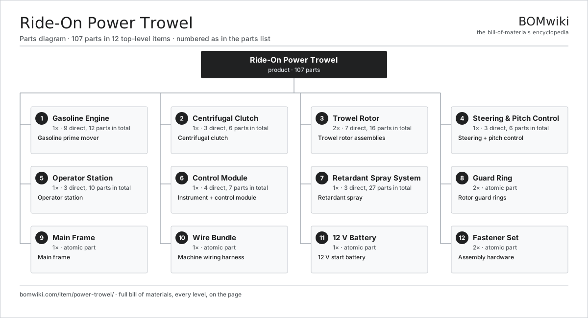
| # | Part | Qty | What it does |
|---|---|---|---|
| 1 | Gasoline Engine 9 parts | 1× | Gasoline prime mover |
| 2 | Centrifugal Clutch 3 parts | 1× | Centrifugal clutch |
| 3 | Trowel Rotor 7 parts | 2× | Trowel rotor assemblies |
| 4 | Steering & Pitch Control 3 parts | 1× | Steering + pitch control |
| 5 | Operator Station 3 parts | 1× | Operator station |
| 6 | Control Module 4 parts | 1× | Instrument + control module |
| 7 | Retardant Spray System 3 parts | 1× | Retardant spray |
| 8 | Guard Ring | 2× | Rotor guard rings |
| 9 | Main Frame | 1× | Main frame |
| 10 | Wire Bundle | 1× | Machine wiring harness |
| 11 | 12 V Battery | 1× | 12 V start battery |
| 12 | Fastener Set | 2× | Assembly hardware |
3D model
No 3D model yet. Have a CAD file of this? Add a 3D model. STL renders right on this page; STEP, FreeCAD, and OpenSCAD sources are welcome too (openly licensed, like all 3D models on BOMwiki).
Build & assembly graph
expand / collapse · shared sub-assemblies converge · links to related products · est. labourTap an assembly to expand/collapse · tap a part to open it · use “Open page” for any node · drag to pan, scroll to zoom.
Bill of materials for Ride-On Power Trowel
12 top-level lines · 53 rows shown · 107 parts total · indented to 3 levels| # | Item / sub-assembly | Part no. | Qty/assy | Ext. qty | Parts | Type |
|---|---|---|---|---|---|---|
| 1 | Gasoline Engine 9 parts | power-trowel-engine | 1× | 1 | 12 | assembly |
| 1.1 | Engine Block | power-trowel-engine-block | 1× | 1 | · | part |
| 1.2 | Piston & Rod | power-trowel-piston | 2× | 2 | · | part |
| 1.3 | Crankshaft | power-trowel-crankshaft | 1× | 1 | · | part |
| 1.4 | Carburetor | power-trowel-carburetor | 1× | 1 | · | part |
| 1.5 | Air Filter | power-trowel-air-filter | 1× | 1 | · | part |
| 1.6 | Spark Plug | spark-plug | 2× | 2 | · | part |
| 1.7 | Exhaust Muffler | power-trowel-muffler | 1× | 1 | · | part |
| 1.8 | Fuel Tank | power-trowel-fuel-tank | 1× | 1 | · | part |
| 1.9 | Ball Bearing | ball-bearing | 2× | 2 | · | part |
| 2 | Centrifugal Clutch 3 parts | power-trowel-clutch | 1× | 1 | 6 | assembly |
| 2.1 | Clutch Drum & Pulley | power-trowel-clutch-drum | 1× | 1 | · | part |
| 2.2 | Clutch Shoe | power-trowel-clutch-shoe | 3× | 3 | · | part |
| 2.3 | Drive Belt | drive-belt | 2× | 2 | · | part |
| 3 | Trowel Rotor 7 parts | power-trowel-rotor | 2× | 2 | 16 | assembly |
| 3.1 | Gearbox Housing | gearbox-housing | 1× | 2 | · | part |
| 3.2 | Helical Gear Pair | gear-pair | 1× | 2 | · | part |
| 3.3 | Blade Spider | power-trowel-spider | 1× | 2 | · | part |
| 3.4 | Trowel Blade | power-trowel-blade | 4× | 8 | · | part |
| 3.5 | Blade Arm | power-trowel-blade-arm | 4× | 8 | · | part |
| 3.6 | Ball Bearing | ball-bearing | 3× | 6 | · | part |
| 3.7 | Oil Seal | oil-seal | 2× | 4 | · | part |
| 4 | Steering & Pitch Control 3 parts | power-trowel-steering | 1× | 1 | 6 | assembly |
| 4.1 | Steering Lever | power-trowel-steer-lever | 2× | 2 | · | part |
| 4.2 | Pitch Linkage | power-trowel-pitch-linkage | 2× | 2 | · | part |
| 4.3 | Rotor Gimbal | power-trowel-gimbal | 2× | 2 | · | part |
| 5 | Operator Station 3 parts | power-trowel-seat | 1× | 1 | 10 | assembly |
| 5.1 | Seat Assembly 5 parts | seat-assembly | 1× | 1 | 7 | assembly |
| 5.1.1 | Seat Frame | seat-frame | 1× | 1 | · | part |
| 5.1.2 | Seat Foam | seat-foam | 2× | 2 | · | part |
| 5.1.3 | Seat Cover | seat-cover | 1× | 1 | · | part |
| 5.1.4 | Seat Motor | seat-motor | 2× | 2 | · | part |
| 5.1.5 | Seat Heater Mat | seat-heater | 1× | 1 | · | part |
| 5.2 | Footrest | power-trowel-footrest | 2× | 2 | · | part |
| 5.3 | Throttle Pedal | power-trowel-throttle-pedal | 1× | 1 | · | part |
| 6 | Control Module 4 parts | power-trowel-controls | 1× | 1 | 7 | assembly |
| 6.1 | Bare PCB | pcb-bare | 1× | 1 | · | part |
| 6.2 | Microcontroller | mcu | 1× | 1 | · | part |
| 6.3 | Instrument Cluster | power-trowel-instrument | 1× | 1 | · | part |
| 6.4 | Connector | connector | 4× | 4 | · | part |
| 7 | Retardant Spray System 3 parts | power-trowel-spray-system | 1× | 1 | 27 | assembly |
| 7.1 | Retardant Tank | power-trowel-spray-tank | 1× | 1 | · | part |
| 7.2 | Spray Pump 4 parts | power-trowel-spray-pump | 1× | 1 | 24 | assembly |
| 7.2.1 | Stator Assembly 3 parts + deeper › | stator-assembly | 1× | 1 | 3 | assembly |
| 7.2.2 | Rotor Assembly 4 parts + deeper › | rotor-assembly | 1× | 1 | 19 | assembly |
| 7.2.3 | Motor Housing | motor-housing | 1× | 1 | · | part |
| 7.2.4 | O-Ring Set | oring-set | 1× | 1 | · | part |
| 7.3 | Spray Nozzle | power-trowel-spray-nozzle | 2× | 2 | · | part |
| 8 | Guard Ring | power-trowel-guard-ring | 2× | 2 | · | part |
| 9 | Main Frame | power-trowel-frame | 1× | 1 | · | part |
| 10 | Wire Bundle | wire-bundle | 1× | 1 | · | part |
| 11 | 12 V Battery | lv-battery | 1× | 1 | · | part |
| 12 | Fastener Set | fastener-set | 2× | 2 | · | part |
Something wrong in this list? Report a problem with this BOM.
Related products
same domain, ranked by shared parts Walk-Behind Concrete Saw
103 parts · shares 13 with this page
Pile Driver
519 parts · shares 22 with this page
 Soil Stabilizer / Reclaimer
166 parts · shares 22 with this page
 Pile Driving Rig
530 parts · shares 21 with this page
 Asphalt Paver
402 parts · shares 21 with this page
 Bulldozer
412 parts · shares 21 with this page
Sourcing: possible vendors
Browse the supplier directory → Prices, MOQ, and lead times are algorithmic estimates, not quotes, and not claims about these companies. Company mappings are curated by keyword; est. price band $15k–$2M. How estimates work| Vendor | HQ | Specialty | MOQ | Lead time |
|---|---|---|---|---|
| caterpillar.com ↗ | Irving, US | Construction & mining equipment | made to order | 16–28 wks |
|
🇯🇵Komatsu
komatsu.com ↗
|
Tokyo, JP | Construction & mining equipment | made to order | 16–28 wks |
|
🇸🇪Volvo CE
volvoce.com ↗
|
Gothenburg, SE | Construction equipment | made to order | 16–28 wks |
|
🇨🇭Liebherr
liebherr.com ↗
|
Bulle, CH | Cranes & heavy equipment | made to order | 16–28 wks |
|
🇨🇳XCMG
xcmg.com ↗
|
Xuzhou, CN | Construction machinery | made to order | 16–28 wks |
342-word article