Soil Stabilization Binder Spreader
ProductOverview
A soil stabilization binder spreader is a tank body mounted on a truck chassis that lays a precise, even layer of dry powdered binder across a roadway subgrade. The binder, usually quicklime, hydrated lime, or portland cement, is later tilled into the soil by a separate reclaimer and watered, where it reacts with the clay to dry it out, raise its strength, and stop it from swelling. The whole result depends on putting down the right mass of binder per square metre, evenly, with as little of the fine, caustic powder going airborne as possible. That is the job this machine does: meter a controlled stream of powder and spread it flat.
The body is built around a sealed Binder Tank that holds the binder. The Aeration System system keeps the powder flowing, the Discharge System meters it out, the Spread Bar lays it across the width, and the Dust Control System system keeps it on the ground. The Rate Control System tie rate to ground speed, and the Chassis Interface interface powers it from the truck.
The binder tank
The Binder Tank is a sealed pressure vessel because dry binder is filled pneumatically from a tanker. Its Tank Shell holds the load, and a steep Discharge Cone funnels powder to the discharge so nothing bridges or stays behind. Binder is loaded through a sealed Fill Hatch, and during filling the Relief Valve vents excess pressure while a Vent Filter filter lets air escape without losing powder to the air. Two Level Sensor units report how much binder is left so the operator knows when to refill.
Aeration and discharge
Dry lime and cement do not flow like a liquid on their own, so the Aeration System system fluidizes them. A Air Blower driven by a Blower Motor pushes filtered air through a Air Manifold into Aeration Pad units in the cone floor. Air bubbling up through the powder makes it behave like a fluid that drains cleanly to the outlet. From there the Discharge System system meters it. A Metering Gate sets the opening, a Rotary Airlock airlock pulls a measured volume out while sealing the tank, and Feed Auger augers carry it to the spread bar, all driven by a Feed Motor. The tank rides on Load Cell sensors so the system can weigh the mass leaving the tank rather than guess at it.
Spreading the binder
The Spread Bar turns a single feed stream into an even layer across the lane. Inside the Bar Housing, a Flow Divider splits the powder so every Spread Outlet gets the same share, and a Outlet Deflector at each outlet fans its ribbon into an even band near the ground. Each outlet has a Outlet Shutoff so the operator can narrow the spread width to match the lane or work around obstacles, and two Bar Cylinder rams raise the bar for transport and lower it to within a few centimetres of the soil to keep the powder from drifting.
Dust control
Lime and cement dust is fine, caustic, and a serious nuisance, so the Dust Control System system is not optional. A Dust Shroud encloses the spread bar so the powder falls inside it rather than blowing across the site, and a flexible Ground Skirt seals the shroud to the ground. For the fines that still try to escape, a Water Pump draws from a Water Tank and feeds Mist Nozzle sprays that wet the airborne dust so it settles immediately. Good dust control also keeps the laid rate accurate, because powder that blows away is binder that did not reach the soil.
Rate control and chassis
The Rate Control System make the machine accurate. The Rate Controller reads a Speed Sensor for ground speed and the tank Load Cell weight, then drives the feeder so the mass laid per square metre stays on target regardless of speed. A GPS Receiver receiver maps coverage to prevent gaps and double-application, and the Operator Display shows target rate, actual rate, and area covered. Everything mounts on a truck through the Chassis Interface interface: a Subframe ties the body to the rails, a PTO Pump driven off the truck powers the hydraulics held in the Hydraulic Reservoir, and a Control Valve routes oil to the feeder, blower, and cylinders.
Use in stabilization work
The spreader is the first machine in a soil stabilization train. It drives slowly across the prepared subgrade laying binder at the rate the soils engineer specified, then a reclaimer mixes the binder into the top three hundred or so millimetres of soil, water is added, and a roller compacts the treated layer. On wet clay subgrades, quicklime is spread to dry and modify the soil so equipment can work the site at all; for a stronger, longer-lasting layer, cement is used. The value the machine adds is precision and dust control: an even, correct application means the treated layer reaches design strength without wasting expensive binder or coating the neighborhood in caustic powder. Because the powder is hazardous and the rate matters to the structural result, weigh-based metering and the dust shroud are what separate a stabilization spreader from a simple sand or salt spreader.
Soil Stabilization Binder Spreader parts and their functions
7 top-level parts · 131 parts in total · full bill of materials below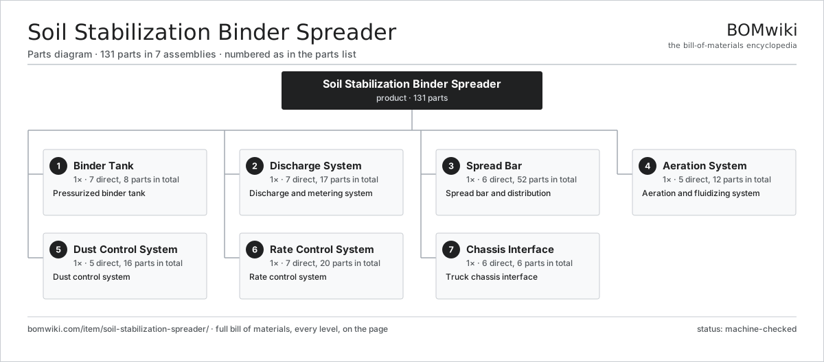
| # | Part | Qty | What it does |
|---|---|---|---|
| 1 | Binder Tank 7 parts | 1× | Pressurized binder tank |
| 2 | Discharge System 7 parts | 1× | Discharge and metering system |
| 3 | Spread Bar 6 parts | 1× | Spread bar and distribution |
| 4 | Aeration System 5 parts | 1× | Aeration and fluidizing system |
| 5 | Dust Control System 5 parts | 1× | Dust control system |
| 6 | Rate Control System 7 parts | 1× | Rate control system |
| 7 | Chassis Interface 6 parts | 1× | Truck chassis interface |
3D model
No 3D model yet. Have a CAD file of this? Add a 3D model — STL renders right on this page; STEP, FreeCAD, and OpenSCAD sources are welcome too (openly licensed, like all 3D models on BOMwiki).
Build & assembly graph
expand / collapse · shared sub-assemblies converge · links to related products · est. labourTap an assembly to expand/collapse · tap a part to open it · use “Open page” for any node · drag to pan, scroll to zoom.
Bill of materials for Soil Stabilization Binder Spreader
7 top-level lines · 53 rows shown · 131 parts total · indented to 3 levels| # | Item / sub-assembly | Part no. | Qty/assy | Ext. qty | Parts | Type |
|---|---|---|---|---|---|---|
| 1 | Binder Tank 7 parts | soil-stabilization-spreader-tank | 1× | 1 | 8 | assembly |
| 1.1 | Tank Shell | soil-stabilization-spreader-tank-shell | 1× | 1 | · | part |
| 1.2 | Discharge Cone | soil-stabilization-spreader-hopper-cone | 1× | 1 | · | part |
| 1.3 | Fill Hatch | soil-stabilization-spreader-fill-hatch | 1× | 1 | · | part |
| 1.4 | Relief Valve | soil-stabilization-spreader-relief-valve | 1× | 1 | · | part |
| 1.5 | Level Sensor | soil-stabilization-spreader-level-sensor | 2× | 2 | · | part |
| 1.6 | Vent Filter | soil-stabilization-spreader-baghouse-vent | 1× | 1 | · | part |
| 1.7 | Fastener Set | fastener-set | 1× | 1 | · | part |
| 2 | Discharge System 7 parts | soil-stabilization-spreader-discharge | 1× | 1 | 17 | assembly |
| 2.1 | Rotary Airlock | soil-stabilization-spreader-rotary-valve | 1× | 1 | · | part |
| 2.2 | Metering Gate | soil-stabilization-spreader-metering-gate | 1× | 1 | · | part |
| 2.3 | Feed Auger | soil-stabilization-spreader-feed-screw | 2× | 2 | · | part |
| 2.4 | Feed Motor | soil-stabilization-spreader-discharge-motor | 1× | 1 | · | part |
| 2.5 | Load Cell | soil-stabilization-spreader-load-cell | 4× | 4 | · | part |
| 2.6 | Ball Bearing | ball-bearing | 4× | 4 | · | part |
| 2.7 | Oil Seal | oil-seal | 4× | 4 | · | part |
| 3 | Spread Bar 6 parts | soil-stabilization-spreader-spreadbar | 1× | 1 | 52 | assembly |
| 3.1 | Bar Housing | soil-stabilization-spreader-bar-housing | 1× | 1 | · | part |
| 3.2 | Spread Outlet | soil-stabilization-spreader-outlet | 16× | 16 | · | part |
| 3.3 | Flow Divider | soil-stabilization-spreader-flow-divider | 1× | 1 | · | part |
| 3.4 | Outlet Deflector | soil-stabilization-spreader-deflector | 16× | 16 | · | part |
| 3.5 | Bar Cylinder | soil-stabilization-spreader-bar-cylinder | 2× | 2 | · | part |
| 3.6 | Outlet Shutoff | soil-stabilization-spreader-shutoff | 16× | 16 | · | part |
| 4 | Aeration System 5 parts | soil-stabilization-spreader-aeration | 1× | 1 | 12 | assembly |
| 4.1 | Air Blower | soil-stabilization-spreader-blower | 1× | 1 | · | part |
| 4.2 | Aeration Pad | soil-stabilization-spreader-aeration-pad | 8× | 8 | · | part |
| 4.3 | Air Manifold | soil-stabilization-spreader-air-manifold | 1× | 1 | · | part |
| 4.4 | Blower Motor | soil-stabilization-spreader-blower-motor | 1× | 1 | · | part |
| 4.5 | Air Filter | soil-stabilization-spreader-air-filter | 1× | 1 | · | part |
| 5 | Dust Control System 5 parts | soil-stabilization-spreader-dustcontrol | 1× | 1 | 16 | assembly |
| 5.1 | Dust Shroud | soil-stabilization-spreader-dust-shroud | 1× | 1 | · | part |
| 5.2 | Water Tank | soil-stabilization-spreader-water-tank | 1× | 1 | · | part |
| 5.3 | Water Pump | soil-stabilization-spreader-water-pump | 1× | 1 | · | part |
| 5.4 | Mist Nozzle | soil-stabilization-spreader-mist-nozzle | 12× | 12 | · | part |
| 5.5 | Ground Skirt | soil-stabilization-spreader-skirt | 1× | 1 | · | part |
| 6 | Rate Control System 7 parts | soil-stabilization-spreader-controls | 1× | 1 | 20 | assembly |
| 6.1 | Rate Controller 3 parts | soil-stabilization-spreader-controller | 1× | 1 | 3 | assembly |
| 6.1.1 | Bare PCB | pcb-bare | 1× | 1 | · | part |
| 6.1.2 | Microcontroller | mcu | 1× | 1 | · | part |
| 6.1.3 | SMD Passive (R/C/L) | smd-passives | 1× | 1 | · | part |
| 6.2 | Speed Sensor | soil-stabilization-spreader-speed-sensor | 1× | 1 | · | part |
| 6.3 | GPS Receiver | soil-stabilization-spreader-gps | 1× | 1 | · | part |
| 6.4 | Operator Display | soil-stabilization-spreader-display | 1× | 1 | · | part |
| 6.5 | Wiring Harness | soil-stabilization-spreader-harness | 1× | 1 | · | part |
| 6.6 | Connector | connector | 10× | 10 | · | part |
| 6.7 | Relay | relay | 3× | 3 | · | part |
| 7 | Chassis Interface 6 parts | soil-stabilization-spreader-chassis | 1× | 1 | 6 | assembly |
| 7.1 | Subframe | soil-stabilization-spreader-subframe | 1× | 1 | · | part |
| 7.2 | PTO Pump | soil-stabilization-spreader-pto-pump | 1× | 1 | · | part |
| 7.3 | Hydraulic Reservoir | soil-stabilization-spreader-hydraulic-tank | 1× | 1 | · | part |
| 7.4 | Hose Set | soil-stabilization-spreader-hose-set | 1× | 1 | · | part |
| 7.5 | Control Valve | soil-stabilization-spreader-control-valve | 1× | 1 | · | part |
| 7.6 | O-Ring Set | oring-set | 1× | 1 | · | part |
Related products
same domain, ranked by shared parts All-Terrain Mobile Crane
594 parts · shares 5 with this page
All-Terrain Mobile Crane
594 parts · shares 5 with this page
 Asphalt Milling Machine
1,134 parts · shares 5 with this page
Asphalt Milling Machine
1,134 parts · shares 5 with this page
 Asphalt Recycler
226 parts · shares 5 with this page
Bridge Form Traveler
405 parts · shares 5 with this page
Asphalt Recycler
226 parts · shares 5 with this page
Bridge Form Traveler
405 parts · shares 5 with this page
 Bridge Girder Launching Gantry
1,542 parts · shares 5 with this page
Bridge Girder Launching Gantry
1,542 parts · shares 5 with this page
 CFA Piling Rig
611 parts · shares 5 with this page
CFA Piling Rig
611 parts · shares 5 with this page
Sourcing: possible vendors
Prices, MOQ, and lead times are algorithmic estimates, not quotes, and not claims about these companies. Company mappings are curated by keyword; est. price band $15k–$2M. How estimates work| Vendor | HQ | Specialty | MOQ | Lead time |
|---|---|---|---|---|
| caterpillar.com ↗ | Irving, US | Construction & mining equipment | made to order | 16–28 wks |
|
🇯🇵Komatsu
komatsu.com ↗
|
Tokyo, JP | Construction & mining equipment | made to order | 16–28 wks |
|
🇸🇪Volvo CE
volvoce.com ↗
|
Gothenburg, SE | Construction equipment | made to order | 16–28 wks |
|
🇨🇭Liebherr
liebherr.com ↗
|
Bulle, CH | Cranes & heavy equipment | made to order | 16–28 wks |
|
🇨🇳XCMG
xcmg.com ↗
|
Xuzhou, CN | Construction machinery | made to order | 16–28 wks |
990-word article