CFA Piling Rig
ProductOverview
A continuous flight auger rig, usually shortened to CFA rig, drills and concretes a cast-in-place pile in a single sequence without removing the tool from the ground. A long Continuous Flight Auger with helical flighting along its full length is rotated and forced down to the design depth in one pass. The flighting carries spoil up the bore while the auger itself stays in the hole, so the soil walls are supported by the auger and the spoil column the whole time. Once the toe reaches depth, concrete is pumped down the Hollow Stem Tube inside the auger and the auger is rotated slowly and lifted, leaving a continuous concrete column behind the rising toe. A steel reinforcement cage is then plunged into the fluid concrete.
The machine is built on a Crawler Undercarriage that carries a Diesel Powerpack, the Hydraulic System, and a tall Mast and Leader holding the Rotary Drive Head. Every working motion is hydraulic. The diesel engine drives the pumps, the pumps feed the valves, and the valves drive the motors and cylinders for drilling, crowd, hoisting and travel. Operating weight runs from 70 to 130 t, much of it deliberate ballast so the rig can react the drilling torque and resist tipping when the mast is loaded.
Carrier and powerpack
The Crawler Undercarriage is a tracked base with two Track Frame sides linked by extendable beams. Each Track Chain runs on a Drive Sprocket turned by a Track Drive Unit, which combines a Travel Hydraulic Motor with a Planetary Track Reducer. The track gauge is widened on site by the Track Gauge Cylinder units to give a stable footprint, then narrowed for road transport. A heavy Counterweight at the rear balances the forward drilling and lifting loads.
The Diesel Powerpack is built around a turbocharged inline-6 Diesel Engine of about 250 kW with a common-rail Common-Rail Injection System and an SCR After-Treatment Unit unit for Stage V emissions. Engine torque passes through a Pump Distributor Gearbox that drives two Variable-Displacement Pump units. Each is a variable-displacement axial-piston pump whose Swash Plate angle, set by the Pump Flow Regulator, matches flow to demand. A Cooling Pack keeps engine coolant and hydraulic oil within range during sustained high-torque drilling.
Hydraulics and mast
Pump flow reaches the Hydraulic System, whose Main Control Valve Block holds eight Control Spool elements and four Pressure Relief Valve cartridges that cap pressure at roughly 35 MPa. Oil is stored in the Hydraulic Oil Tank, returns through the Return-Line Filter units, and the Hydraulic Accumulator vessels absorb the pressure peaks that come from crowd loading.
The Mast and Leader is a box-section leader 22 to 30 m tall, made from high-strength steel with a Upper Telescopic Mast telescopic section so the rig can reach full pile depth yet still fold for transport. The mast pivots on the Mast Pivot Bearing and is raised by the Mast Erection Cylinder units. Two Mast Guide Rail rails run the length of the mast, and the Crowd Carriage slides along them carrying the rotary head.
Drilling and concreting
The Rotary Drive Head is the heart of the rig. Four Rotary Drive Motor units feed a Rotary Head Gearbox that sums their output into a single Hollow Drive Spindle, producing 150 to 400 kNm. The spindle is hollow so concrete can pass through it into the auger, and it connects to the tool through the Auger Coupling Box. Downward thrust comes from the Crowd System, where the Crowd Cylinder units and the Crowd Winch pull the carriage down the mast at about 200 kN.
The Continuous Flight Auger is a continuous helical Helical Flight Segment welded along the Hollow Stem Tube, tipped with replaceable Auger Cutting Tooth cutters and a Flight Wear Strip on each flight edge. The bottom of the stem is closed by a sacrificial Auger End Cap Valve that keeps soil and water out during drilling and blows clear when concrete pressure builds. When the toe is at depth the Concrete Delivery System takes over: the Concrete Piston Pump, a twin-cylinder piston pump with an S-Tube Transfer Valve, pushes concrete through the Concrete Delivery Line into the Rotary Concrete Swivel, which injects it into the rotating stem past a Swivel High-Pressure Seal. The operator lifts the auger slowly while watching the Concrete Flow Meter, keeping delivered volume ahead of the rising toe so no soil collapses into the column. A Reinforcement Plunger with its Plunger Vibrator Head then drives the rebar cage into the wet concrete.
Materials and construction
The structural steel reflects the load path. The mast and carriage use high-strength plate to keep weight down at height, the Hollow Drive Spindle is forged 34CrNiMo6 to carry torque and concrete pressure together, and the Helical Flight Segment and Flight Wear Strip are abrasion-resistant Hardox grades because the flighting wears fast in granular soils. The Auger Cutting Tooth tips are tungsten carbide. Wear parts on the concrete side, the Delivery Cylinder bores and the S-Tube Transfer Valve, are hard-chromed or cast in wear-resistant steel because abrasive concrete erodes them quickly.
Instrumentation and operation
The Operator Cab and Instrumentation is a ROPS/FOPS shell with an air-suspended Operator Seat and a Control Console carrying the joysticks. The Drilling Instrument Computer logs depth, torque, rotation, crowd force and concrete volume for every pile, using a Depth Measuring Encoder on the mast and the Concrete Flow Meter on the concrete line. The operator reads it on an LCD Panel in the cab. Because a CFA pile is cast blind, with no inspection of the bore, this record is the main quality check: the concreting trace shows whether enough concrete was delivered at every depth and whether the bore stayed full. The main hoist for cages and casing is the Main Service Winch, which shares the drum, motor and brake design used on the crowd winch.
CFA piling suits medium to soft ground where an open bore would collapse, such as sands, silts and soft clays. It is quiet and low-vibration compared with driven piles, which makes it common in urban work. The one-pass method is fast, with a single rig completing many piles a day, but it demands steady coordination between the drilling rate, the withdrawal rate and the concrete supply, since the bore is never left open and the column is formed without casing.
CFA Piling Rig parts and their functions
11 top-level parts · 611 parts in total · full bill of materials below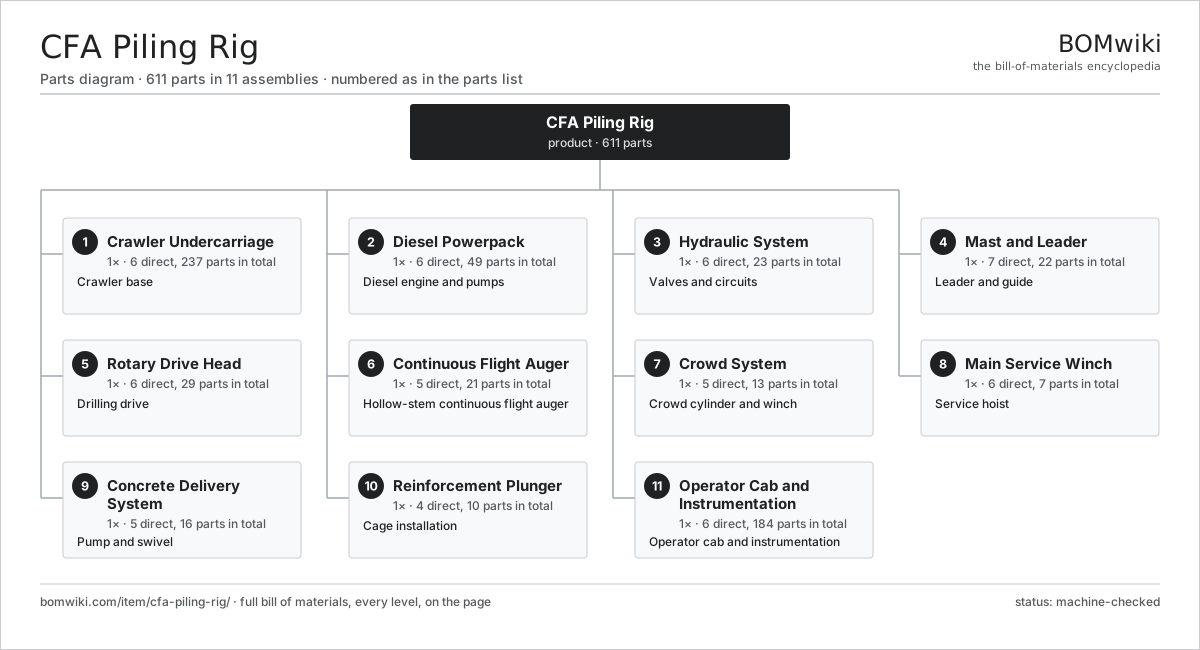
| # | Part | Qty | What it does |
|---|---|---|---|
| 1 | Crawler Undercarriage 6 parts | 1× | Crawler base |
| 2 | Diesel Powerpack 6 parts | 1× | Diesel engine and pumps |
| 3 | Hydraulic System 6 parts | 1× | Valves and circuits |
| 4 | Mast and Leader 7 parts | 1× | Leader and guide |
| 5 | Rotary Drive Head 6 parts | 1× | Drilling drive |
| 6 | Continuous Flight Auger 5 parts | 1× | Hollow-stem continuous flight auger |
| 7 | Crowd System 5 parts | 1× | Crowd cylinder and winch |
| 8 | Main Service Winch 6 parts | 1× | Service hoist |
| 9 | Concrete Delivery System 5 parts | 1× | Pump and swivel |
| 10 | Reinforcement Plunger 4 parts | 1× | Cage installation |
| 11 | Operator Cab and Instrumentation 6 parts | 1× | Operator cab and instrumentation |
3D model
No 3D model yet. Have a CAD file of this? Add a 3D model — STL renders right on this page; STEP, FreeCAD, and OpenSCAD sources are welcome too (openly licensed, like all 3D models on BOMwiki).
Build & assembly graph
expand / collapse · shared sub-assemblies converge · links to related products · est. labourTap an assembly to expand/collapse · tap a part to open it · use “Open page” for any node · drag to pan, scroll to zoom.
Bill of materials for CFA Piling Rig
11 top-level lines · 134 rows shown · 611 parts total · indented to 3 levels| # | Item / sub-assembly | Part no. | Qty/assy | Ext. qty | Parts | Type |
|---|---|---|---|---|---|---|
| 1 | Crawler Undercarriage 6 parts | cfa-piling-rig-undercarriage | 1× | 1 | 237 | assembly |
| 1.1 | Track Frame | cfa-piling-rig-track-frame | 2× | 2 | · | part |
| 1.2 | Track Chain 4 parts | cfa-piling-rig-track-chain | 2× | 2 | 98 | assembly |
| 1.2.1 | Grouser Track Shoe | cfa-piling-rig-track-shoe | 44× | 88 | · | part |
| 1.2.2 | Track Link | cfa-piling-rig-track-link | 44× | 88 | · | part |
| 1.2.3 | Track Roller | cfa-piling-rig-track-roller | 8× | 16 | · | part |
| 1.2.4 | Idler Wheel | cfa-piling-rig-idler-wheel | 2× | 4 | · | part |
| 1.3 | Track Drive Unit 5 parts | cfa-piling-rig-track-drive | 2× | 2 | 16 | assembly |
| 1.3.1 | Travel Hydraulic Motor | cfa-piling-rig-travel-motor | 1× | 2 | · | part |
| 1.3.2 | Planetary Track Reducer 4 parts + deeper › | cfa-piling-rig-planetary-reducer | 1× | 2 | 10 | assembly |
| 1.3.3 | Drive Sprocket | cfa-piling-rig-drive-sprocket | 1× | 2 | · | part |
| 1.3.4 | Ball Bearing | ball-bearing | 2× | 4 | · | part |
| 1.3.5 | Oil Seal | oil-seal | 2× | 4 | · | part |
| 1.4 | Track Gauge Cylinder | cfa-piling-rig-track-extend-cylinder | 2× | 2 | · | part |
| 1.5 | Counterweight | cfa-piling-rig-counterweight | 1× | 1 | · | part |
| 1.6 | Fastener Set | fastener-set | 4× | 4 | · | part |
| 2 | Diesel Powerpack 6 parts | cfa-piling-rig-powerpack | 1× | 1 | 49 | assembly |
| 2.1 | Diesel Engine 6 parts | cfa-piling-rig-diesel-engine | 1× | 1 | 18 | assembly |
| 2.1.1 | Engine Block | cfa-piling-rig-engine-block | 1× | 1 | · | part |
| 2.1.2 | Crankshaft | cfa-piling-rig-crankshaft | 1× | 1 | · | part |
| 2.1.3 | Turbocharger | cfa-piling-rig-turbocharger | 1× | 1 | · | part |
| 2.1.4 | Common-Rail Injection System 3 parts + deeper › | cfa-piling-rig-injection-system | 1× | 1 | 8 | assembly |
| 2.1.5 | SCR After-Treatment Unit 3 parts + deeper › | cfa-piling-rig-after-treatment | 1× | 1 | 3 | assembly |
| 2.1.6 | Oil Seal | oil-seal | 4× | 4 | · | part |
| 2.2 | Pump Distributor Gearbox 4 parts | cfa-piling-rig-pump-distributor | 1× | 1 | 9 | assembly |
| 2.2.1 | Helical Gear Pair | gear-pair | 2× | 2 | · | part |
| 2.2.2 | Gearbox Housing | gearbox-housing | 1× | 1 | · | part |
| 2.2.3 | Ball Bearing | ball-bearing | 4× | 4 | · | part |
| 2.2.4 | Oil Seal | oil-seal | 2× | 2 | · | part |
| 2.3 | Variable-Displacement Pump 5 parts | cfa-piling-rig-main-pump | 2× | 2 | 7 | assembly |
| 2.3.1 | Pump Rotating Group | cfa-piling-rig-pump-rotating-group | 1× | 2 | · | part |
| 2.3.2 | Swash Plate | cfa-piling-rig-swash-plate | 1× | 2 | · | part |
| 2.3.3 | Pump Flow Regulator | cfa-piling-rig-pump-regulator | 1× | 2 | · | part |
| 2.3.4 | Ball Bearing | ball-bearing | 2× | 4 | · | part |
| 2.3.5 | Oil Seal | oil-seal | 2× | 4 | · | part |
| 2.4 | Diesel Fuel Tank | cfa-piling-rig-fuel-tank | 1× | 1 | · | part |
| 2.5 | Cooling Pack 3 parts | cfa-piling-rig-cooling-pack | 1× | 1 | 3 | assembly |
| 2.5.1 | Radiator Core | cfa-piling-rig-radiator-core | 1× | 1 | · | part |
| 2.5.2 | Hydraulic Oil Cooler | cfa-piling-rig-oil-cooler | 1× | 1 | · | part |
| 2.5.3 | Hydraulic Cooling Fan | cfa-piling-rig-cooling-fan | 1× | 1 | · | part |
| 2.6 | Engine Mount | cfa-piling-rig-engine-mount | 4× | 4 | · | part |
| 3 | Hydraulic System 6 parts | cfa-piling-rig-hydraulic-system | 1× | 1 | 23 | assembly |
| 3.1 | Main Control Valve Block 3 parts | cfa-piling-rig-main-control-valve | 1× | 1 | 13 | assembly |
| 3.1.1 | Control Spool | cfa-piling-rig-control-spool | 8× | 8 | · | part |
| 3.1.2 | Pressure Relief Valve | cfa-piling-rig-relief-valve | 4× | 4 | · | part |
| 3.1.3 | Valve Body | cfa-piling-rig-valve-body | 1× | 1 | · | part |
| 3.2 | Hydraulic Oil Tank | cfa-piling-rig-hydraulic-tank | 1× | 1 | · | part |
| 3.3 | Return-Line Filter | cfa-piling-rig-return-filter | 2× | 2 | · | part |
| 3.4 | Hydraulic Accumulator | cfa-piling-rig-accumulator | 2× | 2 | · | part |
| 3.5 | Hydraulic Hose Set | cfa-piling-rig-hose-set | 1× | 1 | · | part |
| 3.6 | O-Ring Set | oring-set | 4× | 4 | · | part |
| 4 | Mast and Leader 7 parts | cfa-piling-rig-mast | 1× | 1 | 22 | assembly |
| 4.1 | Lower Mast Section | cfa-piling-rig-mast-lower | 1× | 1 | · | part |
| 4.2 | Upper Telescopic Mast | cfa-piling-rig-mast-upper | 1× | 1 | · | part |
| 4.3 | Mast Guide Rail | cfa-piling-rig-mast-guide-rail | 2× | 2 | · | part |
| 4.4 | Mast Pivot Bearing 2 parts | cfa-piling-rig-mast-pivot | 1× | 1 | 3 | assembly |
| 4.4.1 | Ball Bearing | ball-bearing | 2× | 2 | · | part |
| 4.4.2 | Pivot Pin | cfa-piling-rig-pivot-pin | 1× | 1 | · | part |
| 4.5 | Mast Erection Cylinder | cfa-piling-rig-mast-erect-cylinder | 2× | 2 | · | part |
| 4.6 | Crowd Carriage 2 parts | cfa-piling-rig-crowd-carriage | 1× | 1 | 9 | assembly |
| 4.6.1 | Carriage Frame | cfa-piling-rig-carriage-frame | 1× | 1 | · | part |
| 4.6.2 | Guide Roller | cfa-piling-rig-guide-roller | 8× | 8 | · | part |
| 4.7 | Fastener Set | fastener-set | 4× | 4 | · | part |
| 5 | Rotary Drive Head 6 parts | cfa-piling-rig-rotary-head | 1× | 1 | 29 | assembly |
| 5.1 | Rotary Drive Motor | cfa-piling-rig-rotary-motor | 4× | 4 | · | part |
| 5.2 | Rotary Head Gearbox 4 parts | cfa-piling-rig-rotary-gearbox | 1× | 1 | 15 | assembly |
| 5.2.1 | Helical Gear Pair | gear-pair | 5× | 5 | · | part |
| 5.2.2 | Gearbox Housing | gearbox-housing | 1× | 1 | · | part |
| 5.2.3 | Ball Bearing | ball-bearing | 6× | 6 | · | part |
| 5.2.4 | Oil Seal | oil-seal | 3× | 3 | · | part |
| 5.3 | Hollow Drive Spindle | cfa-piling-rig-drive-spindle | 1× | 1 | · | part |
| 5.4 | Auger Coupling Box | cfa-piling-rig-kelly-coupling | 1× | 1 | · | part |
| 5.5 | Ball Bearing | ball-bearing | 4× | 4 | · | part |
| 5.6 | Oil Seal | oil-seal | 4× | 4 | · | part |
| 6 | Continuous Flight Auger 5 parts | cfa-piling-rig-auger | 1× | 1 | 21 | assembly |
| 6.1 | Hollow Stem Tube | cfa-piling-rig-hollow-stem | 1× | 1 | · | part |
| 6.2 | Helical Flight Segment | cfa-piling-rig-flight-segment | 1× | 1 | · | part |
| 6.3 | Auger Cutting Tooth | cfa-piling-rig-auger-tooth | 6× | 6 | · | part |
| 6.4 | Auger End Cap Valve | cfa-piling-rig-auger-cap | 1× | 1 | · | part |
| 6.5 | Flight Wear Strip | cfa-piling-rig-wear-strip | 12× | 12 | · | part |
| 7 | Crowd System 5 parts | cfa-piling-rig-crowd-system | 1× | 1 | 13 | assembly |
| 7.1 | Crowd Cylinder | cfa-piling-rig-crowd-cylinder | 2× | 2 | · | part |
| 7.2 | Crowd Winch 4 parts | cfa-piling-rig-crowd-winch | 1× | 1 | 5 | assembly |
| 7.2.1 | Winch Drum | cfa-piling-rig-winch-drum | 1× | 1 | · | part |
| 7.2.2 | Winch Hydraulic Motor | cfa-piling-rig-winch-motor | 1× | 1 | · | part |
| 7.2.3 | Winch Holding Brake | cfa-piling-rig-winch-brake | 1× | 1 | · | part |
| 7.2.4 | Ball Bearing | ball-bearing | 2× | 2 | · | part |
| 7.3 | Crowd Wire Rope | cfa-piling-rig-crowd-rope | 1× | 1 | · | part |
| 7.4 | Crowd Sheave | cfa-piling-rig-crowd-sheave | 4× | 4 | · | part |
| 7.5 | Pressure Sensor | pressure-sensor | 1× | 1 | · | part |
| 8 | Main Service Winch 6 parts | cfa-piling-rig-main-winch | 1× | 1 | 7 | assembly |
| 8.1 | Winch Drum | cfa-piling-rig-winch-drum | 1× | 1 | · | part |
| 8.2 | Winch Hydraulic Motor | cfa-piling-rig-winch-motor | 1× | 1 | · | part |
| 8.3 | Winch Holding Brake | cfa-piling-rig-winch-brake | 1× | 1 | · | part |
| 8.4 | Main Hoist Rope | cfa-piling-rig-main-rope | 1× | 1 | · | part |
| 8.5 | Load Hook with Swivel | cfa-piling-rig-rope-hook | 1× | 1 | · | part |
| 8.6 | Ball Bearing | ball-bearing | 2× | 2 | · | part |
| 9 | Concrete Delivery System 5 parts | cfa-piling-rig-concrete-system | 1× | 1 | 16 | assembly |
| 9.1 | Concrete Piston Pump 5 parts | cfa-piling-rig-concrete-pump | 1× | 1 | 8 | assembly |
| 9.1.1 | Delivery Cylinder | cfa-piling-rig-pump-cylinder | 2× | 2 | · | part |
| 9.1.2 | Pumping Piston | cfa-piling-rig-pump-piston | 2× | 2 | · | part |
| 9.1.3 | S-Tube Transfer Valve | cfa-piling-rig-s-tube-valve | 1× | 1 | · | part |
| 9.1.4 | Concrete Hopper | cfa-piling-rig-hopper | 1× | 1 | · | part |
| 9.1.5 | O-Ring Set | oring-set | 2× | 2 | · | part |
| 9.2 | Rotary Concrete Swivel 3 parts | cfa-piling-rig-concrete-swivel | 1× | 1 | 4 | assembly |
| 9.2.1 | Swivel Body | cfa-piling-rig-swivel-body | 1× | 1 | · | part |
| 9.2.2 | Swivel High-Pressure Seal | cfa-piling-rig-swivel-seal | 1× | 1 | · | part |
| 9.2.3 | Ball Bearing | ball-bearing | 2× | 2 | · | part |
| 9.3 | Concrete Delivery Line | cfa-piling-rig-delivery-line | 1× | 1 | · | part |
| 9.4 | Concrete Flow Meter | cfa-piling-rig-flow-meter | 1× | 1 | · | part |
| 9.5 | Pressure Sensor | pressure-sensor | 2× | 2 | · | part |
| 10 | Reinforcement Plunger 4 parts | cfa-piling-rig-reinforcement-plunger | 1× | 1 | 10 | assembly |
| 10.1 | Plunger Vibrator Head 3 parts | cfa-piling-rig-plunger-vibrator | 1× | 1 | 7 | assembly |
| 10.1.1 | Eccentric Mass | cfa-piling-rig-eccentric-mass | 2× | 2 | · | part |
| 10.1.2 | Ball Bearing | ball-bearing | 4× | 4 | · | part |
| 10.1.3 | Vibrator Housing | cfa-piling-rig-vibrator-housing | 1× | 1 | · | part |
| 10.2 | Plunger Dead Weight | cfa-piling-rig-plunger-weight | 1× | 1 | · | part |
| 10.3 | Rebar Cage Clamp | cfa-piling-rig-cage-clamp | 1× | 1 | · | part |
| 10.4 | Vibrator Hydraulic Motor | cfa-piling-rig-vibrator-motor | 1× | 1 | · | part |
| 11 | Operator Cab and Instrumentation 6 parts | cfa-piling-rig-cab | 1× | 1 | 184 | assembly |
| 11.1 | ROPS/FOPS Cab Shell | cfa-piling-rig-cab-shell | 1× | 1 | · | part |
| 11.2 | Operator Seat | cfa-piling-rig-operator-seat | 1× | 1 | · | part |
| 11.3 | Control Console 4 parts | cfa-piling-rig-control-console | 1× | 1 | 35 | assembly |
| 11.3.1 | Control Joystick | cfa-piling-rig-joystick | 2× | 2 | · | part |
| 11.3.2 | Relay | relay | 8× | 8 | · | part |
| 11.3.3 | Wire Bundle | wire-bundle | 1× | 1 | · | part |
| 11.3.4 | Connector | connector | 24× | 24 | · | part |
| 11.4 | Drilling Instrument Computer 4 parts | cfa-piling-rig-instrument-computer | 1× | 1 | 145 | assembly |
| 11.4.1 | Bare PCB | pcb-bare | 1× | 1 | · | part |
| 11.4.2 | Microcontroller | mcu | 2× | 2 | · | part |
| 11.4.3 | Relay | relay | 2× | 2 | · | part |
| 11.4.4 | SMD Passive (R/C/L) | smd-passives | 140× | 140 | · | part |
| 11.5 | Depth Measuring Encoder | cfa-piling-rig-depth-encoder | 1× | 1 | · | part |
| 11.6 | LCD Panel | lcd-panel | 1× | 1 | · | part |
Related products
same domain, ranked by shared parts All-Terrain Mobile Crane
594 parts · shares 10 with this page
All-Terrain Mobile Crane
594 parts · shares 10 with this page
 Asphalt Milling Machine
1,134 parts · shares 10 with this page
Asphalt Milling Machine
1,134 parts · shares 10 with this page
 Asphalt Recycler
226 parts · shares 10 with this page
Bridge Form Traveler
405 parts · shares 10 with this page
Asphalt Recycler
226 parts · shares 10 with this page
Bridge Form Traveler
405 parts · shares 10 with this page
 Bridge Girder Launching Gantry
1,542 parts · shares 10 with this page
Bridge Girder Launching Gantry
1,542 parts · shares 10 with this page
 Cold Planer
1,646 parts · shares 10 with this page
Cold Planer
1,646 parts · shares 10 with this page
Sourcing: possible vendors
Prices, MOQ, and lead times are algorithmic estimates, not quotes, and not claims about these companies. Company mappings are curated by keyword; est. price band $15k–$2M. How estimates work| Vendor | HQ | Specialty | MOQ | Lead time |
|---|---|---|---|---|
| caterpillar.com ↗ | Irving, US | Construction & mining equipment | made to order | 16–28 wks |
|
🇯🇵Komatsu
komatsu.com ↗
|
Tokyo, JP | Construction & mining equipment | made to order | 16–28 wks |
|
🇸🇪Volvo CE
volvoce.com ↗
|
Gothenburg, SE | Construction equipment | made to order | 16–28 wks |
|
🇨🇭Liebherr
liebherr.com ↗
|
Bulle, CH | Cranes & heavy equipment | made to order | 16–28 wks |
|
🇨🇳XCMG
xcmg.com ↗
|
Xuzhou, CN | Construction machinery | made to order | 16–28 wks |
1,241-word article