Truck-Mounted Aerial Platform
ProductOverview
A truck-mounted aerial platform combines a road-legal carrier truck with a hydraulic boom and a person-carrying basket. It lets one or two workers reach heights of 18 to 32 metres for jobs like streetlight maintenance, tree pruning, sign installation, building facade work, and overhead line repair, then drive away to the next site under its own power. The advantage over a self-propelled boom lift is mobility: the unit travels at highway speed between widely separated work points, which suits utility and municipal fleets that cover large service areas.
The machine has two operating identities. As a vehicle it is the Truck Chassis, a commercial truck rated 7.5 to 18 tonnes. As a work tool it is everything bolted to that chassis through the Subframe and Turret: the outriggers, the boom, the basket, and the hydraulics that the truck engine drives through a power take-off.
Carrier and turret
The Truck Chassis supplies the diesel Carrier Engine, the road Road Transmission, the driver cab, and the running gear. The key adaptation is the Power Take-Off, a gear unit that taps the transmission to drive the hydraulic pump while the truck is parked. The aerial equipment sits on a Subframe and Turret that distributes the boom loads into the chassis rails and carries a large toothed Slew Ring Bearing. A Slew Drive rotates the Turret continuously through 360 degrees so the basket can be positioned anywhere around the truck without repositioning the vehicle.
Outriggers and stability
Before the boom can be raised, the truck must be lifted off its road suspension and made rigid. Four hydraulic Outrigger Leg units extend out and down, each driven by an Outrigger Cylinder that plants a Outrigger Pad on the ground. A Chassis Level Sensor confirms the chassis is within the allowed tilt before the boom controls are enabled. The outrigger geometry sets the stability envelope, and on many machines the available working area shrinks if the legs cannot be fully spread, for example against a curb or wall. The Load Moment Limiter continuously compares the overturning moment of the boom and load against the stabilized footprint.
Boom and reach
The Boom Assembly usually combines an articulating riser with a telescopic main boom and a small jib, which gives both height and the ability to reach up and over an obstacle such as a building parapet. An articulating Lower Boom lifts the assembly clear of nearby structures, a multi-stage Telescopic Boom extends working height and outreach, and a Fly Jib at the tip provides fine up-and-over positioning. Motion comes from Lift Cylinder and Telescope Cylinder units, with replaceable Wear Pad slides between the telescoping sections and hardened Boom Pivot Pin joints at every pivot.
Work platform and leveling
The operator stands in the Work Platform, an enclosed basket with a guardrail and a self-closing gate, rated to carry 230 to 450 kg of people and tools. A Platform Load Cell weighs the contents against the rating and disables further extension if the basket is overloaded. Rated Anchor Point fittings let occupants clip on a fall-arrest harness, and a Basket Rotator turns the basket to square it up to the work. Throughout the boom's travel a Basket Leveling System keeps the floor horizontal: a Leveling Master Cylinder at the boom foot senses the boom angle and a Leveling Slave Cylinder at the basket mount tilts the platform back to level, corrected by a Basket Inclinometer sensor.
Hydraulics and controls
The Hydraulic System runs from a PTO-driven Hydraulic Pump feeding a proportional Main Control Valve bank. A critical safety element is the Emergency Power Unit, a battery-powered DC unit that can retract and lower the boom if the engine or main pump fails while a worker is aloft. Control is split between the primary Upper Control Console console in the basket and a Ground Control Panel panel at ground level used for setup and rescue. A dual-channel Safety Controller reads Boom Angle Sensor and Boom Length Sensor feedback to enforce the working envelope, and Emergency Stop switches at both stations cut all motion instantly.
Variants and use
Units are classified by working height and by carrier weight, which together decide whether a standard car or truck license is needed to drive them. Lighter 18 to 22 metre units on 7.5 tonne chassis serve street lighting and tree crews; heavier 28 to 32 metre units on 16 to 18 tonne chassis reach building facades and tall structures. Insulated variants for electric utility line work use a non-conductive boom tip section and a dielectric basket liner so crews can work near energized conductors. All units are governed by platform standards such as EN 280 and ANSI A92.2, which dictate the stability tests, the load and moment limiting, and the emergency descent requirement.
Truck-Mounted Aerial Platform parts and their functions
8 top-level parts · 388 parts in total · full bill of materials below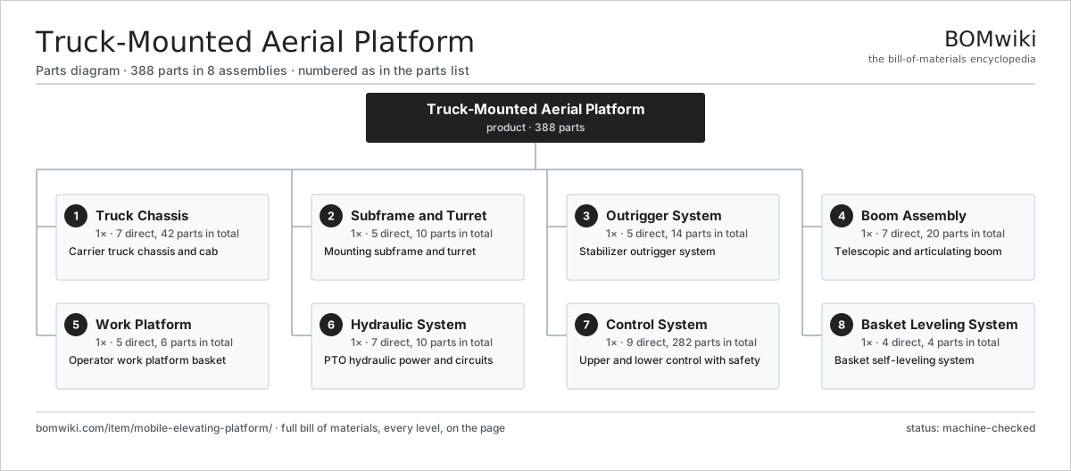
| # | Part | Qty | What it does |
|---|---|---|---|
| 1 | Truck Chassis 7 parts | 1× | Carrier truck chassis and cab |
| 2 | Subframe and Turret 5 parts | 1× | Mounting subframe and turret |
| 3 | Outrigger System 5 parts | 1× | Stabilizer outrigger system |
| 4 | Boom Assembly 7 parts | 1× | Telescopic and articulating boom |
| 5 | Work Platform 5 parts | 1× | Operator work platform basket |
| 6 | Hydraulic System 7 parts | 1× | PTO hydraulic power and circuits |
| 7 | Control System 9 parts | 1× | Upper and lower control with safety |
| 8 | Basket Leveling System 4 parts | 1× | Basket self-leveling system |
3D model
No 3D model yet. Have a CAD file of this? Add a 3D model — STL renders right on this page; STEP, FreeCAD, and OpenSCAD sources are welcome too (openly licensed, like all 3D models on BOMwiki).
Build & assembly graph
expand / collapse · shared sub-assemblies converge · links to related products · est. labourTap an assembly to expand/collapse · tap a part to open it · use “Open page” for any node · drag to pan, scroll to zoom.
Bill of materials for Truck-Mounted Aerial Platform
8 top-level lines · 85 rows shown · 388 parts total · indented to 3 levels| # | Item / sub-assembly | Part no. | Qty/assy | Ext. qty | Parts | Type |
|---|---|---|---|---|---|---|
| 1 | Truck Chassis 7 parts | mobile-elevating-platform-truck-chassis | 1× | 1 | 42 | assembly |
| 1.1 | Chassis Rail | mobile-elevating-platform-chassis-rail | 2× | 2 | · | part |
| 1.2 | Carrier Engine 5 parts | mobile-elevating-platform-truck-engine | 1× | 1 | 8 | assembly |
| 1.2.1 | Engine Block | mobile-elevating-platform-engine-block | 1× | 1 | · | part |
| 1.2.2 | Turbocharger | mobile-elevating-platform-turbocharger | 1× | 1 | · | part |
| 1.2.3 | Fuel System | mobile-elevating-platform-fuel-system | 1× | 1 | · | part |
| 1.2.4 | Ball Bearing | ball-bearing | 3× | 3 | · | part |
| 1.2.5 | Oil Seal | oil-seal | 2× | 2 | · | part |
| 1.3 | Road Transmission 4 parts | mobile-elevating-platform-road-transmission | 1× | 1 | 10 | assembly |
| 1.3.1 | Helical Gear Pair | gear-pair | 3× | 3 | · | part |
| 1.3.2 | Gearbox Housing | gearbox-housing | 1× | 1 | · | part |
| 1.3.3 | Ball Bearing | ball-bearing | 4× | 4 | · | part |
| 1.3.4 | Oil Seal | oil-seal | 2× | 2 | · | part |
| 1.4 | Driver Cab | mobile-elevating-platform-driver-cab | 1× | 1 | · | part |
| 1.5 | Road Axle 4 parts | mobile-elevating-platform-road-axle | 2× | 2 | 7 | assembly |
| 1.5.1 | Axle Beam | mobile-elevating-platform-axle-beam | 1× | 2 | · | part |
| 1.5.2 | Brake Assembly | mobile-elevating-platform-brake-drum | 2× | 4 | · | part |
| 1.5.3 | Ball Bearing | ball-bearing | 2× | 4 | · | part |
| 1.5.4 | Coil Spring | coil-spring | 2× | 4 | · | part |
| 1.6 | Road Wheel | mobile-elevating-platform-road-wheel | 6× | 6 | · | part |
| 1.7 | Power Take-Off | mobile-elevating-platform-pto | 1× | 1 | · | part |
| 2 | Subframe and Turret 5 parts | mobile-elevating-platform-subframe | 1× | 1 | 10 | assembly |
| 2.1 | Subframe Beam | mobile-elevating-platform-subframe-beam | 2× | 2 | · | part |
| 2.2 | Slew Ring Bearing | mobile-elevating-platform-slew-bearing | 1× | 1 | · | part |
| 2.3 | Turret | mobile-elevating-platform-turret | 1× | 1 | · | part |
| 2.4 | Slew Drive 4 parts | mobile-elevating-platform-slew-drive | 1× | 1 | 5 | assembly |
| 2.4.1 | Helical Gear Pair | gear-pair | 1× | 1 | · | part |
| 2.4.2 | Gearbox Housing | gearbox-housing | 1× | 1 | · | part |
| 2.4.3 | Slew Motor | mobile-elevating-platform-slew-motor | 1× | 1 | · | part |
| 2.4.4 | Ball Bearing | ball-bearing | 2× | 2 | · | part |
| 2.5 | Fastener Set | fastener-set | 1× | 1 | · | part |
| 3 | Outrigger System 5 parts | mobile-elevating-platform-outrigger-set | 1× | 1 | 14 | assembly |
| 3.1 | Outrigger Leg | mobile-elevating-platform-outrigger-leg | 4× | 4 | · | part |
| 3.2 | Outrigger Cylinder | mobile-elevating-platform-outrigger-cylinder | 4× | 4 | · | part |
| 3.3 | Outrigger Pad | mobile-elevating-platform-outrigger-pad | 4× | 4 | · | part |
| 3.4 | Chassis Level Sensor | mobile-elevating-platform-level-sensor | 1× | 1 | · | part |
| 3.5 | Outrigger Valve | mobile-elevating-platform-outrigger-valve | 1× | 1 | · | part |
| 4 | Boom Assembly 7 parts | mobile-elevating-platform-boom-assembly | 1× | 1 | 20 | assembly |
| 4.1 | Lower Boom | mobile-elevating-platform-lower-boom | 1× | 1 | · | part |
| 4.2 | Telescopic Boom | mobile-elevating-platform-telescopic-boom | 1× | 1 | · | part |
| 4.3 | Fly Jib | mobile-elevating-platform-jib | 1× | 1 | · | part |
| 4.4 | Lift Cylinder | mobile-elevating-platform-lift-cylinder | 2× | 2 | · | part |
| 4.5 | Telescope Cylinder | mobile-elevating-platform-telescope-cylinder | 1× | 1 | · | part |
| 4.6 | Boom Pivot Pin | mobile-elevating-platform-boom-pin | 6× | 6 | · | part |
| 4.7 | Wear Pad | mobile-elevating-platform-wear-pad | 8× | 8 | · | part |
| 5 | Work Platform 5 parts | mobile-elevating-platform-work-cage | 1× | 1 | 6 | assembly |
| 5.1 | Cage Frame | mobile-elevating-platform-cage-frame | 1× | 1 | · | part |
| 5.2 | Guardrail Set | mobile-elevating-platform-cage-rail | 1× | 1 | · | part |
| 5.3 | Basket Rotator | mobile-elevating-platform-cage-rotator | 1× | 1 | · | part |
| 5.4 | Platform Load Cell | mobile-elevating-platform-load-cell | 1× | 1 | · | part |
| 5.5 | Anchor Point | mobile-elevating-platform-anchor-point | 2× | 2 | · | part |
| 6 | Hydraulic System 7 parts | mobile-elevating-platform-hydraulic-system | 1× | 1 | 10 | assembly |
| 6.1 | Hydraulic Pump | mobile-elevating-platform-hyd-pump | 1× | 1 | · | part |
| 6.2 | Hydraulic Tank | mobile-elevating-platform-hyd-tank | 1× | 1 | · | part |
| 6.3 | Main Control Valve | mobile-elevating-platform-control-valve | 1× | 1 | · | part |
| 6.4 | Hydraulic Filter | mobile-elevating-platform-hyd-filter | 2× | 2 | · | part |
| 6.5 | Emergency Power Unit 3 parts | mobile-elevating-platform-emergency-pump | 1× | 1 | 3 | assembly |
| 6.5.1 | DC Pump Motor | mobile-elevating-platform-dc-motor | 1× | 1 | · | part |
| 6.5.2 | Backup Pump | mobile-elevating-platform-backup-pump | 1× | 1 | · | part |
| 6.5.3 | Backup Battery | mobile-elevating-platform-battery | 1× | 1 | · | part |
| 6.6 | Hydraulic Hose Harness | mobile-elevating-platform-hyd-hose | 1× | 1 | · | part |
| 6.7 | O-Ring Set | oring-set | 1× | 1 | · | part |
| 7 | Control System 9 parts | mobile-elevating-platform-control-system | 1× | 1 | 282 | assembly |
| 7.1 | Upper Control Console 4 parts | mobile-elevating-platform-upper-control | 1× | 1 | 84 | assembly |
| 7.1.1 | Bare PCB | pcb-bare | 1× | 1 | · | part |
| 7.1.2 | Microcontroller | mcu | 1× | 1 | · | part |
| 7.1.3 | Control Joystick | mobile-elevating-platform-joystick | 2× | 2 | · | part |
| 7.1.4 | SMD Passive (R/C/L) | smd-passives | 80× | 80 | · | part |
| 7.2 | Ground Control Panel | mobile-elevating-platform-lower-control | 1× | 1 | · | part |
| 7.3 | Safety Controller 4 parts | mobile-elevating-platform-main-ecu | 1× | 1 | 169 | assembly |
| 7.3.1 | Bare PCB | pcb-bare | 1× | 1 | · | part |
| 7.3.2 | Microcontroller | mcu | 2× | 2 | · | part |
| 7.3.3 | Relay | relay | 6× | 6 | · | part |
| 7.3.4 | SMD Passive (R/C/L) | smd-passives | 160× | 160 | · | part |
| 7.4 | Load Moment Limiter | mobile-elevating-platform-moment-limiter | 1× | 1 | · | part |
| 7.5 | Boom Angle Sensor | mobile-elevating-platform-angle-sensor | 3× | 3 | · | part |
| 7.6 | Boom Length Sensor | mobile-elevating-platform-length-sensor | 1× | 1 | · | part |
| 7.7 | Emergency Stop | mobile-elevating-platform-estop | 2× | 2 | · | part |
| 7.8 | Wire Bundle | wire-bundle | 1× | 1 | · | part |
| 7.9 | Connector | connector | 20× | 20 | · | part |
| 8 | Basket Leveling System 4 parts | mobile-elevating-platform-leveling-system | 1× | 1 | 4 | assembly |
| 8.1 | Leveling Master Cylinder | mobile-elevating-platform-master-cylinder | 1× | 1 | · | part |
| 8.2 | Leveling Slave Cylinder | mobile-elevating-platform-slave-cylinder | 1× | 1 | · | part |
| 8.3 | Leveling Valve | mobile-elevating-platform-level-valve | 1× | 1 | · | part |
| 8.4 | Basket Inclinometer | mobile-elevating-platform-basket-incline | 1× | 1 | · | part |
Related products
same domain, ranked by shared parts Bridge Girder Launching Gantry
1,542 parts · shares 9 with this page
Bridge Girder Launching Gantry
1,542 parts · shares 9 with this page
 Cold Planer
1,646 parts · shares 9 with this page
Cold Planer
1,646 parts · shares 9 with this page
 Crawler Dozer
1,111 parts · shares 9 with this page
Crawler Dozer
1,111 parts · shares 9 with this page
 Crawler Excavator
1,241 parts · shares 9 with this page
Crawler Excavator
1,241 parts · shares 9 with this page
 Crawler Tractor
1,361 parts · shares 9 with this page
Crawler Tractor
1,361 parts · shares 9 with this page
 Drilling Rig Truck
310 parts · shares 9 with this page
Drilling Rig Truck
310 parts · shares 9 with this page
Sourcing: possible vendors
Prices, MOQ, and lead times are algorithmic estimates, not quotes, and not claims about these companies. Company mappings are curated by keyword; est. price band $15k–$2M. How estimates work| Vendor | HQ | Specialty | MOQ | Lead time |
|---|---|---|---|---|
| caterpillar.com ↗ | Irving, US | Construction & mining equipment | made to order | 16–28 wks |
|
🇯🇵Komatsu
komatsu.com ↗
|
Tokyo, JP | Construction & mining equipment | made to order | 16–28 wks |
|
🇸🇪Volvo CE
volvoce.com ↗
|
Gothenburg, SE | Construction equipment | made to order | 16–28 wks |
|
🇨🇭Liebherr
liebherr.com ↗
|
Bulle, CH | Cranes & heavy equipment | made to order | 16–28 wks |
|
🇨🇳XCMG
xcmg.com ↗
|
Xuzhou, CN | Construction machinery | made to order | 16–28 wks |
912-word article