Bulldozer Ripper Attachment
ProductOverview
A bulldozer ripper attachment is a rear-mounted tool that breaks ground too hard for a blade alone to cut. One or more steel shanks are forced down into rock, cemented hardpan, frozen soil, or root-bound earth, and as the dozer drives forward the tips tear the material into loose pieces that the blade can then push. Ripping is cheaper and faster than drilling and blasting for ground that is hard but not solid rock, and it lets a single machine both loosen and move material. The attachment must withstand very high forces: the tractor weight and traction all concentrate at the tip, so the frame, shank, and linkage are built heavy.
The ripper hangs off the rear of the dozer through the Drawbar Mount and is carried by the Ripper Mainframe. The cutting is done by the Shank and Tip, the depth and angle are set by the Lift and Pitch Linkage and the Hydraulic Cylinders, and oil is fed by the Hydraulic Plumbing.
Mainframe and mounting
The Ripper Mainframe is the structural core. Its Frame Weldment is a box section of high-strength plate, tied across by a Cross Tube that resists the twisting load when a single shank catches on one side. The shanks drop through Shank Pocket slots that let depth be pinned, and every link pivot runs on a replaceable Frame Bushing. The whole frame attaches to the tractor through the Drawbar Mount: a pair of Mount Bracket brackets bolt to the dozer rear and take the load through Mount Pin pins and Trunnion bosses, with a Fastener Set of graded bolts. Because the ripping force reacts back through this mount, the brackets are matched to the specific tractor.
Shank and tip
The Shank and Tip does the work. The Shank is a forged alloy-steel leg, curved so that forward travel drives the tip deeper and the broken ground lifts and falls away. At its point is the Ripper Tip, a hard cast part held by a Tip Pin so it can be knocked off and renewed when worn, sparing the expensive shank. A Shank Protector bolts above the tip to shield the leading face from abrasion. Depth is set by moving the shank in its pocket and locking it with a Depth Pin; a shallow setting rips a thin layer fast, while a deep setting in a single hard pass needs all the down-force the machine can make. Operators often run one shank in the hardest ground and add shanks where the material breaks more easily.
Linkage and cylinders
How the tip enters the ground is controlled by the Lift and Pitch Linkage. A parallelogram of two Upper Link and two Lower Link links, joined by Link Pin pins running in Link Bushing bushings, keeps the shank at a chosen pitch through its travel. The Hydraulic Cylinders supplies the force: two Lift Cylinder cylinders raise the frame for travel and push it down to start a cut, while an adjustable ripper adds a Tip Cylinder that changes the pitch angle on the move so the operator can dig the tip in or back it off without stopping. Each Lift Cylinder is a honed Cylinder Tube with a chromed Piston Rod, a Piston, and an O-Ring Set, pinned with Cylinder Pin pins. Down-force matters because the tip must be pressed in hard enough to bite before traction can pull it through the ground.
Hydraulics
Oil comes from the tractor through the Hydraulic Plumbing. A Control Valve section meters flow to the lift and tip cylinders from the dozer implement pump, carried by a Hose Set of high-pressure hoses through rated Connector ends. A Relief Valve caps the pressure when the tip strikes a block it cannot break, so the cylinders and frame are not overloaded; the operator then lifts, repositions, and tries another line. Protecting the system from these shock loads is part of why a ripper lasts in ground that would quickly damage a lighter tool.
Use and variants
Rippers earn their place in site preparation, road and dam building, mining, and quarrying wherever the ground resists the blade but does not warrant blasting. They loosen shale, sandstone, caliche, frozen overburden, and old pavement, and they tear out stumps and root mats in land clearing. The main variants are the single-shank ripper for the hardest material, where all the force goes to one tip, and the multi-shank ripper for fractured rock and ripping a wide swath in one pass. Adjustable parallelogram rippers, with their Tip Cylinder, let the operator tune the tip angle to the ground, while simpler radial rippers fix the angle and trade adjustability for lower cost. Sizing follows the dozer, since the frame and shank must take the full traction and weight of the machine pressing on a single point.
Bulldozer Ripper Attachment parts and their functions
6 top-level parts · 63 parts in total · full bill of materials below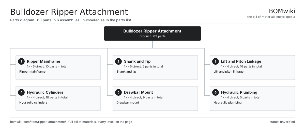
| # | Part | Qty | What it does |
|---|---|---|---|
| 1 | Ripper Mainframe 5 parts | 1× | Ripper mainframe |
| 2 | Shank and Tip 5 parts | 1× | Shank and tip |
| 3 | Lift and Pitch Linkage 4 parts | 1× | Lift and pitch linkage |
| 4 | Hydraulic Cylinders 4 parts | 1× | Hydraulic cylinders |
| 5 | Drawbar Mount 4 parts | 1× | Drawbar mount |
| 6 | Hydraulic Plumbing 4 parts | 1× | Hydraulic plumbing |
3D model
No 3D model yet. Have a CAD file of this? Add a 3D model — STL renders right on this page; STEP, FreeCAD, and OpenSCAD sources are welcome too (openly licensed, like all 3D models on BOMwiki).
Build & assembly graph
expand / collapse · shared sub-assemblies converge · links to related products · est. labourTap an assembly to expand/collapse · tap a part to open it · use “Open page” for any node · drag to pan, scroll to zoom.
Bill of materials for Bulldozer Ripper Attachment
6 top-level lines · 36 rows shown · 63 parts total · indented to 3 levels| # | Item / sub-assembly | Part no. | Qty/assy | Ext. qty | Parts | Type |
|---|---|---|---|---|---|---|
| 1 | Ripper Mainframe 5 parts | ripper-attachment-mainframe | 1× | 1 | 10 | assembly |
| 1.1 | Frame Weldment | ripper-attachment-frame-weldment | 1× | 1 | · | part |
| 1.2 | Shank Pocket | ripper-attachment-shank-pocket | 3× | 3 | · | part |
| 1.3 | Cross Tube | ripper-attachment-cross-tube | 1× | 1 | · | part |
| 1.4 | Frame Bushing | ripper-attachment-frame-bushing | 4× | 4 | · | part |
| 1.5 | Fastener Set | fastener-set | 1× | 1 | · | part |
| 2 | Shank and Tip 5 parts | ripper-attachment-shank-set | 1× | 1 | 5 | assembly |
| 2.1 | Shank | ripper-attachment-shank | 1× | 1 | · | part |
| 2.2 | Ripper Tip | ripper-attachment-tip | 1× | 1 | · | part |
| 2.3 | Shank Protector | ripper-attachment-shank-protector | 1× | 1 | · | part |
| 2.4 | Tip Pin | ripper-attachment-tip-pin | 1× | 1 | · | part |
| 2.5 | Depth Pin | ripper-attachment-depth-pin | 1× | 1 | · | part |
| 3 | Lift and Pitch Linkage 4 parts | ripper-attachment-linkage | 1× | 1 | 16 | assembly |
| 3.1 | Upper Link | ripper-attachment-upper-link | 2× | 2 | · | part |
| 3.2 | Lower Link | ripper-attachment-lower-link | 2× | 2 | · | part |
| 3.3 | Link Pin | ripper-attachment-link-pin | 6× | 6 | · | part |
| 3.4 | Link Bushing | ripper-attachment-link-bushing | 6× | 6 | · | part |
| 4 | Hydraulic Cylinders 4 parts | ripper-attachment-cylinder-set | 1× | 1 | 18 | assembly |
| 4.1 | Lift Cylinder 4 parts | ripper-attachment-lift-cylinder | 2× | 2 | 4 | assembly |
| 4.1.1 | Cylinder Tube | ripper-attachment-cyl-tube | 1× | 2 | · | part |
| 4.1.2 | Piston Rod | ripper-attachment-cyl-rod | 1× | 2 | · | part |
| 4.1.3 | Piston | ripper-attachment-cyl-piston | 1× | 2 | · | part |
| 4.1.4 | O-Ring Set | oring-set | 1× | 2 | · | part |
| 4.2 | Tip Cylinder | ripper-attachment-tip-cylinder | 1× | 1 | · | part |
| 4.3 | O-Ring Set | oring-set | 3× | 3 | · | part |
| 4.4 | Cylinder Pin | ripper-attachment-cylinder-pin | 6× | 6 | · | part |
| 5 | Drawbar Mount 4 parts | ripper-attachment-mount | 1× | 1 | 9 | assembly |
| 5.1 | Mount Bracket | ripper-attachment-mount-bracket | 2× | 2 | · | part |
| 5.2 | Mount Pin | ripper-attachment-mount-pin | 4× | 4 | · | part |
| 5.3 | Trunnion | ripper-attachment-trunnion | 2× | 2 | · | part |
| 5.4 | Fastener Set | fastener-set | 1× | 1 | · | part |
| 6 | Hydraulic Plumbing 4 parts | ripper-attachment-hydraulics | 1× | 1 | 5 | assembly |
| 6.1 | Hose Set | ripper-attachment-hose-set | 1× | 1 | · | part |
| 6.2 | Control Valve | ripper-attachment-control-valve | 1× | 1 | · | part |
| 6.3 | Relief Valve | ripper-attachment-relief-valve | 1× | 1 | · | part |
| 6.4 | Connector | connector | 2× | 2 | · | part |
Related products
same domain, ranked by shared parts All-Terrain Mobile Crane
594 parts · shares 1 with this page
All-Terrain Mobile Crane
594 parts · shares 1 with this page
 Articulated Dump Truck
128 parts · shares 1 with this page
Articulated Dump Truck
128 parts · shares 1 with this page
 Articulated Haul Truck
128 parts · shares 1 with this page
Articulated Haul Truck
128 parts · shares 1 with this page
 Asphalt Distributor Truck
113 parts · shares 1 with this page
Asphalt Distributor Truck
113 parts · shares 1 with this page
 Asphalt Milling Machine
1,134 parts · shares 1 with this page
Asphalt Milling Machine
1,134 parts · shares 1 with this page
 Asphalt Paver
402 parts · shares 1 with this page
Asphalt Paver
402 parts · shares 1 with this page
Sourcing: possible vendors
Prices, MOQ, and lead times are algorithmic estimates, not quotes, and not claims about these companies. Company mappings are curated by keyword; est. price band $15k–$2M. How estimates work| Vendor | HQ | Specialty | MOQ | Lead time |
|---|---|---|---|---|
| caterpillar.com ↗ | Irving, US | Construction & mining equipment | made to order | 16–28 wks |
|
🇯🇵Komatsu
komatsu.com ↗
|
Tokyo, JP | Construction & mining equipment | made to order | 16–28 wks |
|
🇸🇪Volvo CE
volvoce.com ↗
|
Gothenburg, SE | Construction equipment | made to order | 16–28 wks |
|
🇨🇭Liebherr
liebherr.com ↗
|
Bulle, CH | Cranes & heavy equipment | made to order | 16–28 wks |
|
🇨🇳XCMG
xcmg.com ↗
|
Xuzhou, CN | Construction machinery | made to order | 16–28 wks |
871-word article