Scissor Lift
ProductAlso known as: electric scissor lift, scissor lift platform
Overview
An electric scissor lift is a self-propelled mobile elevating work platform that raises a deck straight up on a stack of crossed folding arms. The crossing arms give the machine its name: seen from the side, each pair forms an X, and a column of these X shapes folds nearly flat at ground level and unfolds to lift the platform vertically. Because the motion is purely vertical, the deck always stays directly over the Base Chassis, which keeps the footprint small and makes the machine well suited to indoor work in warehouses, factories, and shopping centres. Working heights run from about 6 m on a compact slab unit to 12 m on a tall model, with the platform floor itself sitting roughly 2 m below those figures.
Everything runs on battery power. There is no engine and no exhaust, so the lift can work indoors all day, and the solid non-marking Driven Rear Wheel and Steered Front Wheel tyres leave clean floors. A typical machine weighs between 1.5 and 3.5 t, most of it concentrated low in the base to keep the centre of gravity down while the platform is up.
Base Chassis
The structural foundation is the Welded Base Frame, a welded steel box-section weldment that carries the wheels at its corners and the lower ends of the scissor stack along its length. Inside it sits the Battery Tray, a sunken compartment that places the heavy battery as low as possible. Keeping that mass near the floor is what lets a narrow machine stay stable with the platform fully raised.
Two safety devices live on the base. The Pothole Protection Bar bars deploy automatically as the platform rises, dropping to within a few centimetres of the floor so the chassis cannot fall into a floor opening or off a dock edge while elevated. The lower arms of the stack attach through the Lower Scissor Pin joints, and their sliding ends run along a Scissor Roller Track bolted to the frame.
Scissor Stack and Lift
Lifting is done entirely by the Scissor Stack. It is built from Scissor Arm beams crossed in pairs and pinned at their centres by a Center Pivot Pin. One end of each arm is pinned to the frame or deck, and the other end carries a Slide Roller that travels along the track. When the arms are pulled toward the horizontal they fold down; when they are pushed toward the vertical they unfold and the stack grows taller. A typical mid-height unit uses around 8 arms in 4 crossed pairs. Every joint runs on a Pivot Bushing to control wear, and a Squaring Tie Rod keeps the stack square so the deck rises level.
The force comes from the Lift System. A Hydraulic Power Pack combines a DC motor, a pump, and a small reservoir, and it runs only while the platform is rising. It feeds a single Lift Cylinder mounted low between the bottom arms. Pushing those arms apart at the base forces the whole stack to open. Lowering does not use the pump at all: the Lowering Control Valve meters oil back out of the cylinder so the platform descends under its own weight at a fixed, controlled speed. A Velocity Fuse at the cylinder port locks the oil in place if a hose ever bursts, holding the platform where it is rather than letting it drop. A Pressure Sensor on the cylinder reads the load.
Work Platform
The crew stands on the Work Platform. Its Deck Frame is pinned to the top arms through the Upper Scissor Pin joints, and the Deck Floor Plate is a slip-resistant plate. A Folding Guardrail surrounds all four sides and folds down so the machine clears low doorways when stowed, with a Toe Board at the deck edge to stop dropped tools and an Entry Gate that closes itself behind the operator. A manual Roll-Out Extension Deck rolls out to reach over a machine or rack, then slides back in for travel.
Drive and Steering
The Drive & Steer System moves the machine around the floor. Two Traction Drive Motor units power the rear wheels, each through a Wheel Drive Gearbox and a Helical Gear Pair final reduction. Steering is at the front, where a Steering Cylinder turns the linkage carrying the front wheels. A spring-applied Parking Brake on each rear wheel locks automatically the moment drive power is removed, so the machine holds position on a grade without any operator action. Travel speed is reduced automatically once the platform is raised, dropping from around 4-5 km/h on the ground to a slow creep when elevated.
Power System
The Power System supplies every circuit on the machine. A 24 or 48 V Battery Pack is the only energy source, recharged overnight by the built-in Onboard Charger from a wall outlet. A Motor Controller sets the speed of both the traction motors and the pump motor, recovering energy and giving smooth starts. Power is switched by Power Contactor units, protected through the DC Fuse Block, and distributed by a Wire Bundle running from base to platform, with several Relay devices handling auxiliary loads.
Control and Safety
Operation centres on the Control System. The operator drives, steers, and lifts from the Platform Control Box using a proportional Control Joystick, and the Ground Control Box at the base allows a worker to lower a stranded platform from the floor. Several sensors guard the work envelope. A Tilt Sensor blocks raising when the chassis is on too steep a slope, since the machine is far less stable elevated on a grade. A Platform Load Sensor stops the lift if the deck is loaded beyond its rated capacity, and a Height Limit Switch pair marks the travel ends. An Emergency Stop Button button at both positions cuts all power at once. The logic runs on a Microcontroller and Bare PCB node populated with SMD Passive (R/C/L), and these machines are certified to EN 280 or ANSI A92.20 for mobile elevating work platforms.
Scissor Lift parts and their functions
7 top-level parts · 110 parts in total · full bill of materials below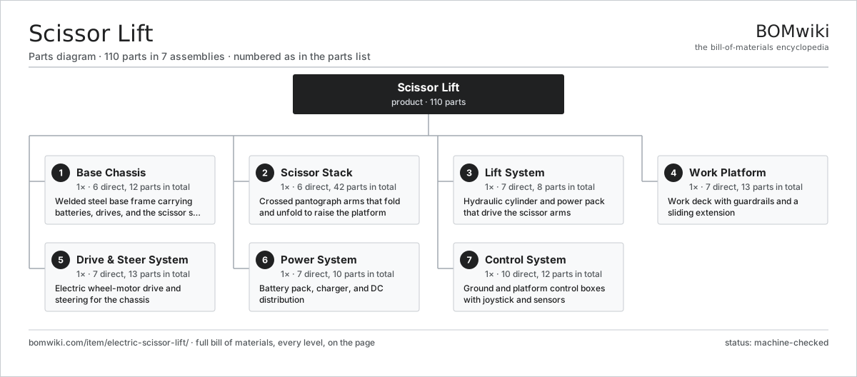
| # | Part | Qty | What it does |
|---|---|---|---|
| 1 | Base Chassis 6 parts | 1× | Welded steel base frame carrying batteries, drives, and the scissor stack |
| 2 | Scissor Stack 6 parts | 1× | Crossed pantograph arms that fold and unfold to raise the platform |
| 3 | Lift System 7 parts | 1× | Hydraulic cylinder and power pack that drive the scissor arms |
| 4 | Work Platform 7 parts | 1× | Work deck with guardrails and a sliding extension |
| 5 | Drive & Steer System 7 parts | 1× | Electric wheel-motor drive and steering for the chassis |
| 6 | Power System 7 parts | 1× | Battery pack, charger, and DC distribution |
| 7 | Control System 10 parts | 1× | Ground and platform control boxes with joystick and sensors |
3D model
No 3D model yet. Have a CAD file of this? Add a 3D model — STL renders right on this page; STEP, FreeCAD, and OpenSCAD sources are welcome too (openly licensed, like all 3D models on BOMwiki).
Build & assembly graph
expand / collapse · shared sub-assemblies converge · links to related products · est. labourTap an assembly to expand/collapse · tap a part to open it · use “Open page” for any node · drag to pan, scroll to zoom.
Bill of materials for Scissor Lift
7 top-level lines · 57 rows shown · 110 parts total · indented to 3 levels| # | Item / sub-assembly | Part no. | Qty/assy | Ext. qty | Parts | Type |
|---|---|---|---|---|---|---|
| 1 | Base Chassis 6 parts | electric-scissor-lift-chassis | 1× | 1 | 12 | assembly |
| 1.1 | Welded Base Frame | electric-scissor-lift-base-frame | 1× | 1 | · | part |
| 1.2 | Battery Tray | electric-scissor-lift-battery-tray | 1× | 1 | · | part |
| 1.3 | Pothole Protection Bar | electric-scissor-lift-pothole-guard | 2× | 2 | · | part |
| 1.4 | Lower Scissor Pin | electric-scissor-lift-lower-pin | 4× | 4 | · | part |
| 1.5 | Scissor Roller Track | electric-scissor-lift-roller-track | 2× | 2 | · | part |
| 1.6 | Fastener Set | fastener-set | 2× | 2 | · | part |
| 2 | Scissor Stack 6 parts | electric-scissor-lift-scissor-stack | 1× | 1 | 42 | assembly |
| 2.1 | Scissor Arm | electric-scissor-lift-scissor-arm | 8× | 8 | · | part |
| 2.2 | Center Pivot Pin | electric-scissor-lift-center-pin | 4× | 4 | · | part |
| 2.3 | Slide Roller | electric-scissor-lift-slide-roller | 4× | 4 | · | part |
| 2.4 | Pivot Bushing | electric-scissor-lift-pivot-bushing | 16× | 16 | · | part |
| 2.5 | Squaring Tie Rod | electric-scissor-lift-tilt-rod | 2× | 2 | · | part |
| 2.6 | Ball Bearing | ball-bearing | 8× | 8 | · | part |
| 3 | Lift System 7 parts | electric-scissor-lift-lift-system | 1× | 1 | 8 | assembly |
| 3.1 | Lift Cylinder | electric-scissor-lift-lift-cylinder | 1× | 1 | · | part |
| 3.2 | Hydraulic Power Pack | electric-scissor-lift-power-pack | 1× | 1 | · | part |
| 3.3 | Lowering Control Valve | electric-scissor-lift-lowering-valve | 1× | 1 | · | part |
| 3.4 | Velocity Fuse | electric-scissor-lift-velocity-fuse | 1× | 1 | · | part |
| 3.5 | Hydraulic Hose Set | electric-scissor-lift-hose-set | 1× | 1 | · | part |
| 3.6 | Pressure Sensor | pressure-sensor | 1× | 1 | · | part |
| 3.7 | O-Ring Set | oring-set | 2× | 2 | · | part |
| 4 | Work Platform 7 parts | electric-scissor-lift-platform | 1× | 1 | 13 | assembly |
| 4.1 | Deck Frame | electric-scissor-lift-deck-frame | 1× | 1 | · | part |
| 4.2 | Deck Floor Plate | electric-scissor-lift-deck-floor | 1× | 1 | · | part |
| 4.3 | Folding Guardrail | electric-scissor-lift-guardrail | 1× | 1 | · | part |
| 4.4 | Toe Board | electric-scissor-lift-toe-board | 4× | 4 | · | part |
| 4.5 | Entry Gate | electric-scissor-lift-entry-gate | 1× | 1 | · | part |
| 4.6 | Roll-Out Extension Deck | electric-scissor-lift-extension-deck | 1× | 1 | · | part |
| 4.7 | Upper Scissor Pin | electric-scissor-lift-upper-pin | 4× | 4 | · | part |
| 5 | Drive & Steer System 7 parts | electric-scissor-lift-drive-system | 1× | 1 | 13 | assembly |
| 5.1 | Traction Drive Motor | electric-scissor-lift-drive-motor | 2× | 2 | · | part |
| 5.2 | Wheel Drive Gearbox | electric-scissor-lift-drive-gearbox | 2× | 2 | · | part |
| 5.3 | Driven Rear Wheel | electric-scissor-lift-rear-wheel | 2× | 2 | · | part |
| 5.4 | Steered Front Wheel | electric-scissor-lift-front-wheel | 2× | 2 | · | part |
| 5.5 | Steering Cylinder | electric-scissor-lift-steer-cylinder | 1× | 1 | · | part |
| 5.6 | Parking Brake | electric-scissor-lift-brake | 2× | 2 | · | part |
| 5.7 | Helical Gear Pair | gear-pair | 2× | 2 | · | part |
| 6 | Power System 7 parts | electric-scissor-lift-power-system | 1× | 1 | 10 | assembly |
| 6.1 | Battery Pack | electric-scissor-lift-battery-pack | 1× | 1 | · | part |
| 6.2 | Onboard Charger | electric-scissor-lift-charger | 1× | 1 | · | part |
| 6.3 | Motor Controller | electric-scissor-lift-motor-controller | 1× | 1 | · | part |
| 6.4 | Power Contactor | electric-scissor-lift-contactor | 2× | 2 | · | part |
| 6.5 | DC Fuse Block | electric-scissor-lift-fuse-block | 1× | 1 | · | part |
| 6.6 | Relay | relay | 3× | 3 | · | part |
| 6.7 | Wire Bundle | wire-bundle | 1× | 1 | · | part |
| 7 | Control System 10 parts | electric-scissor-lift-control-system | 1× | 1 | 12 | assembly |
| 7.1 | Platform Control Box | electric-scissor-lift-platform-box | 1× | 1 | · | part |
| 7.2 | Ground Control Box | electric-scissor-lift-ground-box | 1× | 1 | · | part |
| 7.3 | Control Joystick | electric-scissor-lift-joystick | 1× | 1 | · | part |
| 7.4 | Tilt Sensor | electric-scissor-lift-tilt-sensor | 1× | 1 | · | part |
| 7.5 | Platform Load Sensor | electric-scissor-lift-load-sensor | 1× | 1 | · | part |
| 7.6 | Height Limit Switch | electric-scissor-lift-height-switch | 2× | 2 | · | part |
| 7.7 | Emergency Stop Button | electric-scissor-lift-estop | 2× | 2 | · | part |
| 7.8 | Bare PCB | pcb-bare | 1× | 1 | · | part |
| 7.9 | Microcontroller | mcu | 1× | 1 | · | part |
| 7.10 | SMD Passive (R/C/L) | smd-passives | 1× | 1 | · | part |
Related products
same domain, ranked by shared parts All-Terrain Mobile Crane
594 parts · shares 7 with this page
All-Terrain Mobile Crane
594 parts · shares 7 with this page
 Asphalt Milling Machine
1,134 parts · shares 7 with this page
Asphalt Milling Machine
1,134 parts · shares 7 with this page
 Asphalt Recycler
226 parts · shares 7 with this page
Bridge Form Traveler
405 parts · shares 7 with this page
Asphalt Recycler
226 parts · shares 7 with this page
Bridge Form Traveler
405 parts · shares 7 with this page
 Bridge Girder Launching Gantry
1,542 parts · shares 7 with this page
Bridge Girder Launching Gantry
1,542 parts · shares 7 with this page
 CFA Piling Rig
611 parts · shares 7 with this page
CFA Piling Rig
611 parts · shares 7 with this page
Sourcing: possible vendors
Prices, MOQ, and lead times are algorithmic estimates, not quotes, and not claims about these companies. Company mappings are curated by keyword; est. price band $15k–$2M. How estimates work| Vendor | HQ | Specialty | MOQ | Lead time |
|---|---|---|---|---|
| caterpillar.com ↗ | Irving, US | Construction & mining equipment | made to order | 16–28 wks |
|
🇯🇵Komatsu
komatsu.com ↗
|
Tokyo, JP | Construction & mining equipment | made to order | 16–28 wks |
|
🇸🇪Volvo CE
volvoce.com ↗
|
Gothenburg, SE | Construction equipment | made to order | 16–28 wks |
|
🇨🇭Liebherr
liebherr.com ↗
|
Bulle, CH | Cranes & heavy equipment | made to order | 16–28 wks |
|
🇨🇳XCMG
xcmg.com ↗
|
Xuzhou, CN | Construction machinery | made to order | 16–28 wks |
1,119-word article