Mobile Crusher
ProductOverview
A mobile crusher is a self-contained processing plant on crawler tracks that reduces large rock or demolition rubble to a saleable graded product at the point where the material is dug. By bringing the crusher to the face rather than hauling raw rock to a fixed plant, it cuts truck movements and lets a contractor produce aggregate or recycled fill directly on site. The unit described here is a tracked jaw crusher, the most common primary crushing machine for hard rock and reinforced concrete.
Material flows through the machine in a straight line. An excavator loads the Vibrating Grizzly Feeder, which meters rock into the Crushing Unit. The crushed product drops onto the Conveyor System, passes under the Overband Magnet that pulls out tramp iron, and builds a stockpile at the discharge end. The whole plant rides on the Track Undercarriage, drives off a single Diesel Powerpack, and is coordinated by the Control System.
Crushing Unit
The Crushing Unit is a single-toggle jaw crusher. Rock falls into a V-shaped chamber formed by a fixed wall and a moving wall. The Fixed Jaw Die is bolted to the Jaw Crusher Frame, while the Swing Jaw hangs on the Eccentric Shaft. As the shaft turns, its offset throw swings the moving jaw toward and away from the fixed wall, nipping and breaking the rock against the Swing Jaw Die. Both dies are manganese steel, which work-hardens under impact and is the main wear part of the machine.
The bottom of the swing jaw is supported by the Toggle Plate. This plate transmits the crushing reaction but is deliberately the weakest link: if an uncrushable piece such as a digger tooth enters the chamber, the toggle shears and saves the crusher from catastrophic damage. Two cast iron Flywheel units smooth the load, storing energy during the open part of the cycle and releasing it during the crushing stroke so the engine sees a steady draw rather than a series of spikes. Product size is set by the CSS Adjuster, a hydraulic wedge that changes the closed-side setting, the gap at the bottom of the chamber, from 40 to 200 mm without stopping the machine.
Feeder and Scalping
Feed is buffered and metered by the Vibrating Grizzly Feeder, a vibrating grizzly feeder. Rock is loaded into the Feed Hopper, whose folding walls drop for road transport. The Feeder Pan vibrates the rock forward toward the crusher mouth at a rate the control system trims to keep the chamber full but not choked. At the discharge end of the pan, the Grizzly Bars form a tapered deck that lets fines and dirt fall through and bypass the crusher entirely. This scalping protects the crusher from clay and improves product cleanliness, since the fines often carry the most contamination. The pan is driven by eccentric-weight Vibrator Drive units running on hydraulic power.
Conveyors and Magnet
Crushed product leaves the crusher onto the Conveyor System. The Main Product Conveyor is a wide troughed belt that runs under the body of the machine and out the discharge end to build a stockpile. Its rubber Conveyor Belt runs over sealed Idler Roller sets and is driven by a lagged Head Pulley turned by a hydraulic Belt Drive Motor. The frame folds for transport. A second narrow Side Fines Conveyor carries the scalped fines off to one side so they can be sold separately or stockpiled.
Where the feed is demolition concrete, the Overband Magnet is essential. The Magnet Block hangs above the main belt and lifts ferrous tramp metal such as cut rebar out of the product. A cleated Magnet Cleaning Belt carries the captured iron sideways and drops it into a separate pile, so the crushed concrete leaves the plant clean enough to reuse as road base.
Undercarriage and Mobility
The plant moves on a pair of Track Undercarriage assemblies. Each has a welded Track Frame, a sealed Track Chain with bolt-on shoes, lower Track Roller sets, and a hydraulic Track Drive Motor driving the sprocket through a planetary final drive. Travel speed is low, between 0.8 and 1.5 km/h, which is enough to reposition the crusher within a quarry or follow a demolition job across a site. For road transport the machine is loaded onto a low-loader; the conveyors and hopper walls fold to bring it within legal width and height.
Powerpack
The single Diesel Powerpack supplies everything. A six-cylinder turbocharged Diesel Engine of 200 to 350 kW drives the crusher, usually directly through a Crusher Drive Clutch that allows a soft start under the heavy flywheel inertia. The same engine drives two variable-displacement Hydraulic Pump units that power the feeder, the conveyors, the magnet, and the tracks. A combined Cooling Pack handles engine coolant, hydraulic oil, and charge air, drawing from the Hydraulic Tank and the Fuel Tank. Direct mechanical drive of the crusher with hydraulic drive of the auxiliaries is the standard layout because it puts the engine power straight into crushing while keeping the lighter functions flexible.
Control System and Operation
The Control System makes the plant safe and steady to run. A PLC Controller runs the start-up sequence, bringing belts and feeder up in the right order so the discharge clears before the crusher loads. It enforces interlocks that stop the feed if a belt stalls or pressure rises. The Operator Panel gives the operator a touchscreen view of throughput, settings, and faults. A handheld Radio Remote lets one person tram the tracks and start or stop the feeder from a safe distance during set-up.
The key control loop is crusher-level regulation. A Crusher Level Sensor watches the rock level in the chamber and trims the Vibrating Grizzly Feeder stroke to keep the crusher choke-fed, which gives the best product shape and the highest throughput. The Sensor Set also tracks hydraulic pressure and belt speed for overload and slip protection. Wear management drives the economics: jaw dies are flipped and then replaced after a few thousand tonnes, belts and idlers are inspected daily, and the closed-side setting is checked and reset as the dies wear to hold the product gradation within specification.
Mobile Crusher parts and their functions
9 top-level parts · 343 parts in total · full bill of materials below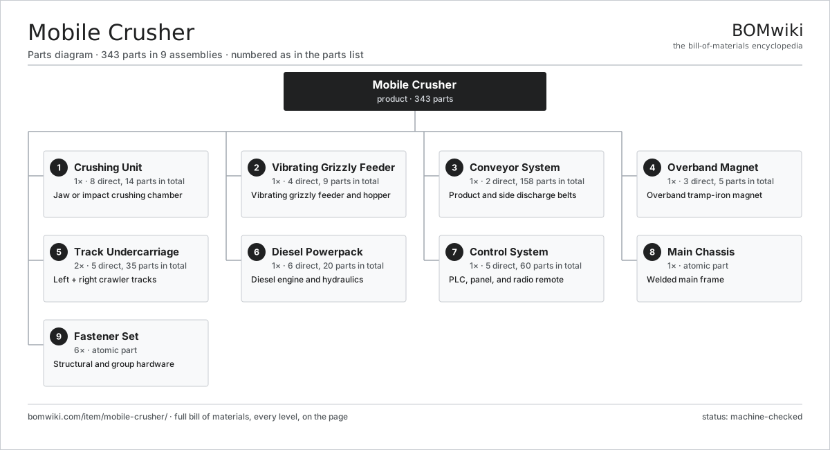
| # | Part | Qty | What it does |
|---|---|---|---|
| 1 | Crushing Unit 8 parts | 1× | Jaw or impact crushing chamber |
| 2 | Vibrating Grizzly Feeder 4 parts | 1× | Vibrating grizzly feeder and hopper |
| 3 | Conveyor System 2 parts | 1× | Product and side discharge belts |
| 4 | Overband Magnet 3 parts | 1× | Overband tramp-iron magnet |
| 5 | Track Undercarriage 5 parts | 2× | Left + right crawler tracks |
| 6 | Diesel Powerpack 6 parts | 1× | Diesel engine and hydraulics |
| 7 | Control System 5 parts | 1× | PLC, panel, and radio remote |
| 8 | Main Chassis | 1× | Welded main frame |
| 9 | Fastener Set | 6× | Structural and group hardware |
3D model
No 3D model yet. Have a CAD file of this? Add a 3D model — STL renders right on this page; STEP, FreeCAD, and OpenSCAD sources are welcome too (openly licensed, like all 3D models on BOMwiki).
Build & assembly graph
expand / collapse · shared sub-assemblies converge · links to related products · est. labourTap an assembly to expand/collapse · tap a part to open it · use “Open page” for any node · drag to pan, scroll to zoom.
Bill of materials for Mobile Crusher
9 top-level lines · 89 rows shown · 343 parts total · indented to 3 levels| # | Item / sub-assembly | Part no. | Qty/assy | Ext. qty | Parts | Type |
|---|---|---|---|---|---|---|
| 1 | Crushing Unit 8 parts | mobile-crusher-crushing-unit | 1× | 1 | 14 | assembly |
| 1.1 | Jaw Crusher Frame | mobile-crusher-jaw-frame | 1× | 1 | · | part |
| 1.2 | Swing Jaw 2 parts | mobile-crusher-swing-jaw | 1× | 1 | 2 | assembly |
| 1.2.1 | Swing Jaw Die | mobile-crusher-swing-jaw-die | 1× | 1 | · | part |
| 1.2.2 | Pitman | mobile-crusher-jaw-stock | 1× | 1 | · | part |
| 1.3 | Fixed Jaw Die | mobile-crusher-fixed-jaw-plate | 1× | 1 | · | part |
| 1.4 | Eccentric Shaft | mobile-crusher-eccentric-shaft | 1× | 1 | · | part |
| 1.5 | Toggle Plate | mobile-crusher-toggle-plate | 1× | 1 | · | part |
| 1.6 | Flywheel | mobile-crusher-flywheel | 2× | 2 | · | part |
| 1.7 | CSS Adjuster 2 parts | mobile-crusher-css-adjuster | 1× | 1 | 2 | assembly |
| 1.7.1 | CSS Cylinder | mobile-crusher-css-cylinder | 1× | 1 | · | part |
| 1.7.2 | O-Ring Set | oring-set | 1× | 1 | · | part |
| 1.8 | Ball Bearing | ball-bearing | 4× | 4 | · | part |
| 2 | Vibrating Grizzly Feeder 4 parts | mobile-crusher-feeder | 1× | 1 | 9 | assembly |
| 2.1 | Feed Hopper | mobile-crusher-hopper | 1× | 1 | · | part |
| 2.2 | Feeder Pan | mobile-crusher-feeder-pan | 1× | 1 | · | part |
| 2.3 | Grizzly Bars | mobile-crusher-grizzly-bars | 1× | 1 | · | part |
| 2.4 | Vibrator Drive 2 parts | mobile-crusher-vibrator-motor | 2× | 2 | 3 | assembly |
| 2.4.1 | Ball Bearing | ball-bearing | 2× | 4 | · | part |
| 2.4.2 | Oil Seal | oil-seal | 1× | 2 | · | part |
| 3 | Conveyor System 2 parts | mobile-crusher-conveyor-system | 1× | 1 | 158 | assembly |
| 3.1 | Main Product Conveyor 5 parts | mobile-crusher-main-conveyor | 1× | 1 | 106 | assembly |
| 3.1.1 | Conveyor Belt | mobile-crusher-conveyor-belt | 1× | 1 | · | part |
| 3.1.2 | Conveyor Frame | mobile-crusher-conveyor-frame | 1× | 1 | · | part |
| 3.1.3 | Idler Roller 2 parts + deeper › | mobile-crusher-idler-roller | 24× | 24 | 4 | assembly |
| 3.1.4 | Conveyor Head Drive 4 parts + deeper › | mobile-crusher-conveyor-drive | 1× | 1 | 7 | assembly |
| 3.1.5 | Tail Pulley | mobile-crusher-tail-pulley | 1× | 1 | · | part |
| 3.2 | Side Fines Conveyor 3 parts | mobile-crusher-side-conveyor | 1× | 1 | 52 | assembly |
| 3.2.1 | Conveyor Belt | mobile-crusher-conveyor-belt | 1× | 1 | · | part |
| 3.2.2 | Idler Roller 2 parts + deeper › | mobile-crusher-idler-roller | 12× | 12 | 4 | assembly |
| 3.2.3 | Belt Drive Motor 2 parts + deeper › | mobile-crusher-belt-motor | 1× | 1 | 3 | assembly |
| 4 | Overband Magnet 3 parts | mobile-crusher-magnet-separator | 1× | 1 | 5 | assembly |
| 4.1 | Magnet Block | mobile-crusher-magnet-block | 1× | 1 | · | part |
| 4.2 | Magnet Cleaning Belt | mobile-crusher-magnet-belt | 1× | 1 | · | part |
| 4.3 | Belt Drive Motor 2 parts | mobile-crusher-belt-motor | 1× | 1 | 3 | assembly |
| 4.3.1 | Ball Bearing | ball-bearing | 2× | 2 | · | part |
| 4.3.2 | Oil Seal | oil-seal | 1× | 1 | · | part |
| 5 | Track Undercarriage 5 parts | mobile-crusher-track-undercarriage | 2× | 2 | 35 | assembly |
| 5.1 | Track Frame | mobile-crusher-track-frame | 1× | 2 | · | part |
| 5.2 | Track Chain | mobile-crusher-track-chain | 1× | 2 | · | part |
| 5.3 | Track Roller 2 parts | mobile-crusher-track-roller | 7× | 14 | 4 | assembly |
| 5.3.1 | Ball Bearing | ball-bearing | 2× | 28 | · | part |
| 5.3.2 | Oil Seal | oil-seal | 2× | 28 | · | part |
| 5.4 | Track Drive Motor 3 parts | mobile-crusher-track-motor | 1× | 2 | 4 | assembly |
| 5.4.1 | Helical Gear Pair | gear-pair | 1× | 2 | · | part |
| 5.4.2 | Ball Bearing | ball-bearing | 2× | 4 | · | part |
| 5.4.3 | Oil Seal | oil-seal | 1× | 2 | · | part |
| 5.5 | Gearbox Housing | gearbox-housing | 1× | 2 | · | part |
| 6 | Diesel Powerpack 6 parts | mobile-crusher-powerpack | 1× | 1 | 20 | assembly |
| 6.1 | Diesel Engine 5 parts | mobile-crusher-diesel-engine | 1× | 1 | 8 | assembly |
| 6.1.1 | Cylinder Block | mobile-crusher-engine-block | 1× | 1 | · | part |
| 6.1.2 | Turbocharger 2 parts + deeper › | mobile-crusher-turbo | 1× | 1 | 2 | assembly |
| 6.1.3 | Radiator | radiator | 1× | 1 | · | part |
| 6.1.4 | Coolant Pump | coolant-pump | 1× | 1 | · | part |
| 6.1.5 | Oil Seal | oil-seal | 3× | 3 | · | part |
| 6.2 | Hydraulic Pump 3 parts | mobile-crusher-hyd-pump | 2× | 2 | 4 | assembly |
| 6.2.1 | Gearbox Housing | gearbox-housing | 1× | 2 | · | part |
| 6.2.2 | Ball Bearing | ball-bearing | 2× | 4 | · | part |
| 6.2.3 | Oil Seal | oil-seal | 1× | 2 | · | part |
| 6.3 | Crusher Drive Clutch | mobile-crusher-clutch | 1× | 1 | · | part |
| 6.4 | Cooling Pack | mobile-crusher-cooling-pack | 1× | 1 | · | part |
| 6.5 | Hydraulic Tank | mobile-crusher-hyd-tank | 1× | 1 | · | part |
| 6.6 | Fuel Tank | mobile-crusher-fuel-tank | 1× | 1 | · | part |
| 7 | Control System 5 parts | mobile-crusher-control-system | 1× | 1 | 60 | assembly |
| 7.1 | PLC Controller 4 parts | mobile-crusher-plc | 1× | 1 | 19 | assembly |
| 7.1.1 | Bare PCB | pcb-bare | 1× | 1 | · | part |
| 7.1.2 | Microcontroller | mcu | 2× | 2 | · | part |
| 7.1.3 | Relay | relay | 8× | 8 | · | part |
| 7.1.4 | Connector | connector | 8× | 8 | · | part |
| 7.2 | Operator Panel 4 parts | mobile-crusher-control-panel | 1× | 1 | 4 | assembly |
| 7.2.1 | LCD Panel | lcd-panel | 1× | 1 | · | part |
| 7.2.2 | Microcontroller | mcu | 1× | 1 | · | part |
| 7.2.3 | Bare PCB | pcb-bare | 1× | 1 | · | part |
| 7.2.4 | Power Supply | power-supply | 1× | 1 | · | part |
| 7.3 | Radio Remote 3 parts | mobile-crusher-radio-remote | 1× | 1 | 3 | assembly |
| 7.3.1 | Bare PCB | pcb-bare | 1× | 1 | · | part |
| 7.3.2 | Microcontroller | mcu | 1× | 1 | · | part |
| 7.3.3 | RF Module | mobile-crusher-radio-module | 1× | 1 | · | part |
| 7.4 | Sensor Set 3 parts | mobile-crusher-sensor-set | 1× | 1 | 6 | assembly |
| 7.4.1 | Pressure Sensor | pressure-sensor | 3× | 3 | · | part |
| 7.4.2 | Crusher Level Sensor | mobile-crusher-level-sensor | 1× | 1 | · | part |
| 7.4.3 | Speed Sensor | mobile-crusher-speed-sensor | 2× | 2 | · | part |
| 7.5 | Wiring Harness 4 parts | mobile-crusher-harness | 1× | 1 | 28 | assembly |
| 7.5.1 | Wire Bundle | wire-bundle | 1× | 1 | · | part |
| 7.5.2 | Connector | connector | 20× | 20 | · | part |
| 7.5.3 | Fuse Box | fuse-box | 1× | 1 | · | part |
| 7.5.4 | Relay | relay | 6× | 6 | · | part |
| 8 | Main Chassis | mobile-crusher-chassis | 1× | 1 | · | part |
| 9 | Fastener Set | fastener-set | 6× | 6 | · | part |
Related products
same domain, ranked by shared parts


Sourcing: possible vendors
Prices, MOQ, and lead times are algorithmic estimates, not quotes, and not claims about these companies. Company mappings are curated by keyword; est. price band $15k–$2M. How estimates work| Vendor | HQ | Specialty | MOQ | Lead time |
|---|---|---|---|---|
| caterpillar.com ↗ | Irving, US | Construction & mining equipment | made to order | 16–28 wks |
|
🇯🇵Komatsu
komatsu.com ↗
|
Tokyo, JP | Construction & mining equipment | made to order | 16–28 wks |
|
🇸🇪Volvo CE
volvoce.com ↗
|
Gothenburg, SE | Construction equipment | made to order | 16–28 wks |
|
🇨🇭Liebherr
liebherr.com ↗
|
Bulle, CH | Cranes & heavy equipment | made to order | 16–28 wks |
|
🇨🇳XCMG
xcmg.com ↗
|
Xuzhou, CN | Construction machinery | made to order | 16–28 wks |
1,119-word article