Ring-Mounted Heavy Crane
ProductOverview
The Ring-Mounted Heavy Crane is a very-high-capacity lift machine used for the heaviest single picks on power plant, refinery, and petrochemical construction sites. Instead of resting on crawler tracks or outriggers, the whole superstructure rotates on a large-diameter steel Load-Bearing Ring laid on prepared ground. The ring spreads the combined load and counterweight reactions over a wide footprint, which keeps ground bearing pressure low enough to work on compacted fill or matting. A machine in this class lifts in the range of 1,600 to 2,200 t and reaches hook heights near 185 m, so it sets reactor vessels, coke drums, flare stacks, and turbine generators that smaller crawler cranes cannot handle.
The crane is shipped as discrete modules and assembled on site. Boom and jib lattice arrives as interchangeable sections, the Load-Bearing Ring arrives as bolted arc segments, and the counterweight arrives as individual slabs. A full mobilization is roughly ninety truckloads and takes a support crew several weeks to erect, ballast, and commission before the first pick.
Load-bearing ring
The Load-Bearing Ring is the structural heart of the machine. Twelve welded box-section Ring Segment arcs bolt together through machined Ring Splice Plate Set plates into a continuous circle thirty meters across. A hardened Ring Running Rail runs along the top flange and carries the rolling load. Beneath the ring, steel Ring Foundation Mat grillage spreads the reaction into the ground so bearing pressure stays under about 25 t/m². The ring also carries a slew rack that the drive pinions engage to rotate the bed.
Load transfers from the superstructure to the rail through banks of Ring Roller Bogie roller trucks. Each bogie uses an equalizer Bogie Equalizer Frame over four flanged Track Roller wheels so the four contact points share load evenly across rail joints and small grade changes.
Rotating bed and slewing
The Rotating Bed is a welded box-girder Bed Frame that carries the boom, masts, winches, and counterweight. It locates on the ring through a central Center Pivot Kingpin kingpin and rides on driven and idler Slew Bogie trucks spaced around the ring. Slewing is powered by several Ring Slew Drive units, each a planetary Hydraulic Drive Motor turning a case-hardened Slew Drive Pinion that meshes the ring rack. A spring-applied Slew Holding Brake holds position when no command is given. Slew speed is deliberately low, around 0.1 rpm, because the rotating inertia of a fully reeved boom and ballasted counterweight is very large.
Boom, jib, and reeving
The Lattice Main Boom is a pinned lattice structure built from a heel Boom Butt Section, a stack of interchangeable Boom Insert Section sections, and a Boom Point Section point that carries the load sheaves. Section length is selected for the lift, from about 36 m up to 130 m. Boom Pendant Bar tension bars suspend the boom from the mast, and Boom Connection Pin quick-release pins join each section. A luffing Luffing Fixed Jib can be added at the boom point to extend reach for tall vessels, supported by its own Jib Backstay Strut backstays and Jib Pendant Bar bars.
The main load passes through the Hook Block, a multi-sheave bottom block with a forged Forged Load Hook. The 38 mm Main Load Rope reeves fourteen falls between the Load Sheave bank at the boom point and the Block Sheave set in the block, which is how four 45 t winch line pulls combine into a lift of over 2,000 t.
Hoist and derricking winches
Two functions move wire rope under load. The Boom Hoist System luffs the boom angle: a gantry Gantry Mast raises the reeving line and a planetary Boom Hoist Winch spools the Boom Hoist Rope over Mast Head Sheave blocks, with Boom Backstop Cylinder cylinders limiting over-travel. The Main Load Hoist raises the load through twin Load Hoist Winch drums. Every winch uses a grooved Winch Drum, a planetary Gearbox Housing reduction, hydraulic Hydraulic Drive Motor drive, and a spring-applied Drum Holding Brake that locks the drum whenever the motor is not commanded.
Counterweight system
A 2,200 t lift produces an overturning moment that has to be balanced by mass on the opposite side of the ring. The Counterweight System system carries up to about 480 t of stacked Counterweight Slab ballast on a Counterweight Tray. The tray rolls on Counterweight Travel Roller wheels and is positioned by Counterweight Cylinder hydraulic rams, so the operator can shift the counterweight radius to match the load moment as the boom luffs and the load swings.
Power and control
A Diesel-Electric Power Pack supplies the machine. A six-cylinder Diesel Engine of about 520 kW drives a brushless Main Generator for the control and lighting loads and a set of variable-displacement Main Hydraulic Pump units for the drive circuits. A Cooling Pack holds engine and oil temperature, and fuel and oil are stored in the Fuel Tank and Hydraulic Reservoir. The Drive Distribution System routes pump flow through load-sensing Proportional Valve Bank banks and Hydraulic Accumulator reservoirs to each winch and motor.
The operator works from the Operator Cab and Control System cab using proportional Control Joystick controls. A Control PLC runs the machine logic, while a separate Load Moment Indicator load moment indicator reads Boom Angle Sensor boom angles, hoist Pressure Sensor line pull, and Anemometer wind speed, then limits motion before the rated load chart is exceeded. Anti-two-block Anti-Two-Block Switch limits stop the hoist before the block reaches the boom point.
Ring-Mounted Heavy Crane parts and their functions
11 top-level parts · 2,831 parts in total · full bill of materials below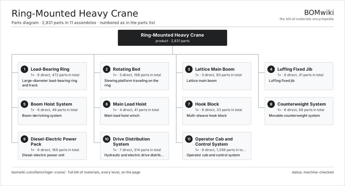
| # | Part | Qty | What it does |
|---|---|---|---|
| 1 | Load-Bearing Ring 6 parts | 1× | Large-diameter load-bearing ring and track |
| 2 | Rotating Bed 5 parts | 1× | Slewing platform traveling on the ring |
| 3 | Lattice Main Boom 5 parts | 1× | Lattice main boom |
| 4 | Luffing Fixed Jib 6 parts | 1× | Luffing fixed jib |
| 5 | Boom Hoist System 6 parts | 1× | Boom derricking system |
| 6 | Main Load Hoist 4 parts | 1× | Main load hoist winch |
| 7 | Hook Block 6 parts | 1× | Multi-sheave hook block |
| 8 | Counterweight System 6 parts | 1× | Movable counterweight system |
| 9 | Diesel-Electric Power Pack 6 parts | 1× | Diesel-electric power unit |
| 10 | Drive Distribution System 7 parts | 1× | Hydraulic and electric drive distribution |
| 11 | Operator Cab and Control System 8 parts | 1× | Operator cab and control system |
3D model
No 3D model yet. Have a CAD file of this? Add a 3D model — STL renders right on this page; STEP, FreeCAD, and OpenSCAD sources are welcome too (openly licensed, like all 3D models on BOMwiki).
Build & assembly graph
expand / collapse · shared sub-assemblies converge · links to related products · est. labourTap an assembly to expand/collapse · tap a part to open it · use “Open page” for any node · drag to pan, scroll to zoom.
Bill of materials for Ring-Mounted Heavy Crane
11 top-level lines · 161 rows shown · 2,831 parts total · indented to 3 levels| # | Item / sub-assembly | Part no. | Qty/assy | Ext. qty | Parts | Type |
|---|---|---|---|---|---|---|
| 1 | Load-Bearing Ring 6 parts | ringer-crane-load-ring | 1× | 1 | 472 | assembly |
| 1.1 | Ring Segment | ringer-crane-ring-segment | 12× | 12 | · | part |
| 1.2 | Ring Running Rail | ringer-crane-ring-rail | 12× | 12 | · | part |
| 1.3 | Ring Roller Bogie 5 parts | ringer-crane-ring-bogie | 16× | 16 | 25 | assembly |
| 1.3.1 | Bogie Equalizer Frame | ringer-crane-bogie-frame | 1× | 16 | · | part |
| 1.3.2 | Track Roller | ringer-crane-track-roller | 4× | 64 | · | part |
| 1.3.3 | Ball Bearing | ball-bearing | 8× | 128 | · | part |
| 1.3.4 | Roller Axle Pin | ringer-crane-roller-axle | 4× | 64 | · | part |
| 1.3.5 | Oil Seal | oil-seal | 8× | 128 | · | part |
| 1.4 | Ring Foundation Mat | ringer-crane-ring-mat | 24× | 24 | · | part |
| 1.5 | Ring Splice Plate Set | ringer-crane-ring-splice | 12× | 12 | · | part |
| 1.6 | Fastener Set | fastener-set | 12× | 12 | · | part |
| 2 | Rotating Bed 5 parts | ringer-crane-rotating-bed | 1× | 1 | 198 | assembly |
| 2.1 | Bed Frame | ringer-crane-bed-frame | 1× | 1 | · | part |
| 2.2 | Center Pivot Kingpin 4 parts | ringer-crane-center-pivot | 1× | 1 | 7 | assembly |
| 2.2.1 | Center Kingpin | ringer-crane-kingpin | 1× | 1 | · | part |
| 2.2.2 | Spherical Pivot Bearing | ringer-crane-pivot-bearing | 1× | 1 | · | part |
| 2.2.3 | Oil Seal | oil-seal | 4× | 4 | · | part |
| 2.2.4 | Fastener Set | fastener-set | 1× | 1 | · | part |
| 2.3 | Slew Bogie 4 parts | ringer-crane-slew-bogie | 8× | 8 | 17 | assembly |
| 2.3.1 | Bogie Equalizer Frame | ringer-crane-bogie-frame | 1× | 8 | · | part |
| 2.3.2 | Track Roller | ringer-crane-track-roller | 4× | 32 | · | part |
| 2.3.3 | Ball Bearing | ball-bearing | 8× | 64 | · | part |
| 2.3.4 | Roller Axle Pin | ringer-crane-roller-axle | 4× | 32 | · | part |
| 2.4 | Ring Slew Drive 7 parts | ringer-crane-ring-drive | 4× | 4 | 13 | assembly |
| 2.4.1 | Slew Drive Pinion | ringer-crane-slew-pinion | 1× | 4 | · | part |
| 2.4.2 | Gearbox Housing | gearbox-housing | 1× | 4 | · | part |
| 2.4.3 | Helical Gear Pair | gear-pair | 2× | 8 | · | part |
| 2.4.4 | Hydraulic Drive Motor | ringer-crane-hyd-motor | 1× | 4 | · | part |
| 2.4.5 | Slew Holding Brake | ringer-crane-slew-brake | 1× | 4 | · | part |
| 2.4.6 | Ball Bearing | ball-bearing | 4× | 16 | · | part |
| 2.4.7 | Oil Seal | oil-seal | 3× | 12 | · | part |
| 2.5 | Boom Foot Pin | ringer-crane-boom-foot-pin | 2× | 2 | · | part |
| 3 | Lattice Main Boom 5 parts | ringer-crane-main-boom | 1× | 1 | 90 | assembly |
| 3.1 | Boom Butt Section | ringer-crane-boom-butt | 1× | 1 | · | part |
| 3.2 | Boom Insert Section | ringer-crane-boom-insert | 8× | 8 | · | part |
| 3.3 | Boom Point Section 4 parts | ringer-crane-boom-top | 1× | 1 | 29 | assembly |
| 3.3.1 | Boom Point Frame | ringer-crane-boom-top-frame | 1× | 1 | · | part |
| 3.3.2 | Load Sheave | ringer-crane-load-sheave | 7× | 7 | · | part |
| 3.3.3 | Ball Bearing | ball-bearing | 14× | 14 | · | part |
| 3.3.4 | Sheave Pin | ringer-crane-sheave-pin | 7× | 7 | · | part |
| 3.4 | Boom Pendant Bar | ringer-crane-boom-pendant | 16× | 16 | · | part |
| 3.5 | Boom Connection Pin | ringer-crane-boom-pin | 36× | 36 | · | part |
| 4 | Luffing Fixed Jib 6 parts | ringer-crane-jib | 1× | 1 | 41 | assembly |
| 4.1 | Jib Lattice Section | ringer-crane-jib-section | 4× | 4 | · | part |
| 4.2 | Jib Backstay Strut | ringer-crane-jib-strut | 2× | 2 | · | part |
| 4.3 | Jib Pendant Bar | ringer-crane-jib-pendant | 8× | 8 | · | part |
| 4.4 | Load Sheave | ringer-crane-load-sheave | 5× | 5 | · | part |
| 4.5 | Ball Bearing | ball-bearing | 10× | 10 | · | part |
| 4.6 | Boom Connection Pin | ringer-crane-boom-pin | 12× | 12 | · | part |
| 5 | Boom Hoist System 6 parts | ringer-crane-boom-hoist | 1× | 1 | 46 | assembly |
| 5.1 | Gantry Mast | ringer-crane-mast | 1× | 1 | · | part |
| 5.2 | Boom Hoist Winch 7 parts | ringer-crane-boom-hoist-winch | 1× | 1 | 18 | assembly |
| 5.2.1 | Winch Drum | ringer-crane-winch-drum | 1× | 1 | · | part |
| 5.2.2 | Gearbox Housing | gearbox-housing | 1× | 1 | · | part |
| 5.2.3 | Helical Gear Pair | gear-pair | 3× | 3 | · | part |
| 5.2.4 | Hydraulic Drive Motor | ringer-crane-hyd-motor | 2× | 2 | · | part |
| 5.2.5 | Drum Holding Brake | ringer-crane-drum-brake | 1× | 1 | · | part |
| 5.2.6 | Ball Bearing | ball-bearing | 6× | 6 | · | part |
| 5.2.7 | Oil Seal | oil-seal | 4× | 4 | · | part |
| 5.3 | Boom Hoist Rope | ringer-crane-boom-hoist-rope | 1× | 1 | · | part |
| 5.4 | Mast Head Sheave | ringer-crane-mast-sheave | 8× | 8 | · | part |
| 5.5 | Boom Backstop Cylinder | ringer-crane-backstop | 2× | 2 | · | part |
| 5.6 | Ball Bearing | ball-bearing | 16× | 16 | · | part |
| 6 | Main Load Hoist 4 parts | ringer-crane-load-hoist | 1× | 1 | 41 | assembly |
| 6.1 | Load Hoist Winch 7 parts | ringer-crane-load-winch | 2× | 2 | 18 | assembly |
| 6.1.1 | Winch Drum | ringer-crane-winch-drum | 1× | 2 | · | part |
| 6.1.2 | Gearbox Housing | gearbox-housing | 1× | 2 | · | part |
| 6.1.3 | Helical Gear Pair | gear-pair | 3× | 6 | · | part |
| 6.1.4 | Hydraulic Drive Motor | ringer-crane-hyd-motor | 2× | 4 | · | part |
| 6.1.5 | Drum Holding Brake | ringer-crane-drum-brake | 1× | 2 | · | part |
| 6.1.6 | Ball Bearing | ball-bearing | 6× | 12 | · | part |
| 6.1.7 | Oil Seal | oil-seal | 4× | 8 | · | part |
| 6.2 | Main Load Rope | ringer-crane-load-rope | 1× | 1 | · | part |
| 6.3 | Rope Dead-End Anchor | ringer-crane-rope-anchor | 2× | 2 | · | part |
| 6.4 | Anti-Two-Block Switch | ringer-crane-overhoist-switch | 2× | 2 | · | part |
| 7 | Hook Block 6 parts | ringer-crane-hook-block | 1× | 1 | 33 | assembly |
| 7.1 | Hook Block Frame | ringer-crane-block-frame | 1× | 1 | · | part |
| 7.2 | Block Sheave | ringer-crane-block-sheave | 7× | 7 | · | part |
| 7.3 | Forged Load Hook | ringer-crane-load-hook | 1× | 1 | · | part |
| 7.4 | Hook Thrust Nut | ringer-crane-hook-nut | 1× | 1 | · | part |
| 7.5 | Ball Bearing | ball-bearing | 16× | 16 | · | part |
| 7.6 | Sheave Pin | ringer-crane-sheave-pin | 7× | 7 | · | part |
| 8 | Counterweight System 6 parts | ringer-crane-counterweight | 1× | 1 | 68 | assembly |
| 8.1 | Counterweight Tray | ringer-crane-cwt-tray | 1× | 1 | · | part |
| 8.2 | Counterweight Slab | ringer-crane-cwt-slab | 40× | 40 | · | part |
| 8.3 | Counterweight Cylinder | ringer-crane-cwt-cylinder | 2× | 2 | · | part |
| 8.4 | Counterweight Travel Roller | ringer-crane-cwt-roller | 8× | 8 | · | part |
| 8.5 | Ball Bearing | ball-bearing | 16× | 16 | · | part |
| 8.6 | Fastener Set | fastener-set | 1× | 1 | · | part |
| 9 | Diesel-Electric Power Pack 6 parts | ringer-crane-power-pack | 1× | 1 | 169 | assembly |
| 9.1 | Diesel Engine 6 parts | ringer-crane-diesel-engine | 1× | 1 | 20 | assembly |
| 9.1.1 | Engine Cylinder Block | ringer-crane-engine-block | 1× | 1 | · | part |
| 9.1.2 | Crankshaft | ringer-crane-crankshaft | 1× | 1 | · | part |
| 9.1.3 | Turbocharger | ringer-crane-turbocharger | 2× | 2 | · | part |
| 9.1.4 | Common-Rail Injector | ringer-crane-fuel-injector | 6× | 6 | · | part |
| 9.1.5 | Ball Bearing | ball-bearing | 4× | 4 | · | part |
| 9.1.6 | Oil Seal | oil-seal | 6× | 6 | · | part |
| 9.2 | Main Generator 5 parts | ringer-crane-generator | 1× | 1 | 109 | assembly |
| 9.2.1 | Stator Assembly 3 parts + deeper › | stator-assembly | 1× | 1 | 3 | assembly |
| 9.2.2 | Rotor Assembly 4 parts + deeper › | rotor-assembly | 1× | 1 | 19 | assembly |
| 9.2.3 | Generator Housing | ringer-crane-gen-housing | 1× | 1 | · | part |
| 9.2.4 | Ball Bearing | ball-bearing | 2× | 2 | · | part |
| 9.2.5 | Automatic Voltage Regulator 4 parts + deeper › | ringer-crane-avr | 1× | 1 | 84 | assembly |
| 9.3 | Main Hydraulic Pump 5 parts | ringer-crane-hyd-pump | 4× | 4 | 8 | assembly |
| 9.3.1 | Pump Housing | ringer-crane-pump-housing | 1× | 4 | · | part |
| 9.3.2 | Piston Barrel | ringer-crane-piston-barrel | 1× | 4 | · | part |
| 9.3.3 | Swash Plate | ringer-crane-swash-plate | 1× | 4 | · | part |
| 9.3.4 | Ball Bearing | ball-bearing | 2× | 8 | · | part |
| 9.3.5 | Oil Seal | oil-seal | 3× | 12 | · | part |
| 9.4 | Cooling Pack 4 parts | ringer-crane-cooling-pack | 1× | 1 | 6 | assembly |
| 9.4.1 | Radiator Core | ringer-crane-radiator-core | 1× | 1 | · | part |
| 9.4.2 | Hydraulic Oil Cooler | ringer-crane-oil-cooler | 1× | 1 | · | part |
| 9.4.3 | Cooling Fan | ringer-crane-cooling-fan | 2× | 2 | · | part |
| 9.4.4 | Hydraulic Drive Motor | ringer-crane-hyd-motor | 2× | 2 | · | part |
| 9.5 | Fuel Tank | ringer-crane-fuel-tank | 1× | 1 | · | part |
| 9.6 | Hydraulic Reservoir | ringer-crane-hyd-tank | 1× | 1 | · | part |
| 10 | Drive Distribution System 7 parts | ringer-crane-drive-system | 1× | 1 | 314 | assembly |
| 10.1 | Proportional Valve Bank 5 parts | ringer-crane-control-valve | 6× | 6 | 25 | assembly |
| 10.1.1 | Valve Body | ringer-crane-valve-body | 1× | 6 | · | part |
| 10.1.2 | Valve Spool | ringer-crane-valve-spool | 4× | 24 | · | part |
| 10.1.3 | Pilot Solenoid | ringer-crane-solenoid | 8× | 48 | · | part |
| 10.1.4 | Coil Spring | coil-spring | 8× | 48 | · | part |
| 10.1.5 | O-Ring Set | oring-set | 4× | 24 | · | part |
| 10.2 | Hydraulic Manifold | ringer-crane-hyd-manifold | 2× | 2 | · | part |
| 10.3 | Hydraulic Hose | ringer-crane-hyd-hose | 80× | 80 | · | part |
| 10.4 | Hydraulic Accumulator | ringer-crane-accumulator | 4× | 4 | · | part |
| 10.5 | Pressure Sensor | pressure-sensor | 12× | 12 | · | part |
| 10.6 | Wire Bundle | wire-bundle | 6× | 6 | · | part |
| 10.7 | Connector | connector | 60× | 60 | · | part |
| 11 | Operator Cab and Control System 8 parts | ringer-crane-cab-control | 1× | 1 | 1,359 | assembly |
| 11.1 | Cab Shell 4 parts | ringer-crane-cab-shell | 1× | 1 | 17 | assembly |
| 11.1.1 | Sheet Metal Panel | sheet-panel | 8× | 8 | · | part |
| 11.1.2 | Cab Glazing | ringer-crane-cab-glass | 5× | 5 | · | part |
| 11.1.3 | Cab HVAC Unit 3 parts + deeper › | ringer-crane-hvac-unit | 1× | 1 | 3 | assembly |
| 11.1.4 | Fastener Set | fastener-set | 1× | 1 | · | part |
| 11.2 | Operator Seat | ringer-crane-operator-seat | 1× | 1 | · | part |
| 11.3 | Control Joystick 4 parts | ringer-crane-joystick | 2× | 2 | 43 | assembly |
| 11.3.1 | Bare PCB | pcb-bare | 1× | 2 | · | part |
| 11.3.2 | Microcontroller | mcu | 1× | 2 | · | part |
| 11.3.3 | Hall-Effect Grip Sensor | ringer-crane-hall-grip | 1× | 2 | · | part |
| 11.3.4 | SMD Passive (R/C/L) | smd-passives | 40× | 80 | · | part |
| 11.4 | Control PLC 5 parts | ringer-crane-plc | 1× | 1 | 1,001 | assembly |
| 11.4.1 | Bare PCB | pcb-bare | 2× | 2 | · | part |
| 11.4.2 | Microcontroller | mcu | 2× | 2 | · | part |
| 11.4.3 | I/O Module 5 parts + deeper › | ringer-crane-io-module | 6× | 6 | 116 | assembly |
| 11.4.4 | Power Supply | power-supply | 1× | 1 | · | part |
| 11.4.5 | SMD Passive (R/C/L) | smd-passives | 300× | 300 | · | part |
| 11.5 | Load Moment Indicator 5 parts | ringer-crane-lmi | 1× | 1 | 126 | assembly |
| 11.5.1 | Bare PCB | pcb-bare | 1× | 1 | · | part |
| 11.5.2 | Microcontroller | mcu | 1× | 1 | · | part |
| 11.5.3 | Pressure Sensor | pressure-sensor | 2× | 2 | · | part |
| 11.5.4 | Boom Angle Sensor | ringer-crane-angle-sensor | 2× | 2 | · | part |
| 11.5.5 | SMD Passive (R/C/L) | smd-passives | 120× | 120 | · | part |
| 11.6 | Operator Display 4 parts | ringer-crane-display | 2× | 2 | 63 | assembly |
| 11.6.1 | LCD Panel | lcd-panel | 1× | 2 | · | part |
| 11.6.2 | Bare PCB | pcb-bare | 1× | 2 | · | part |
| 11.6.3 | Microcontroller | mcu | 1× | 2 | · | part |
| 11.6.4 | SMD Passive (R/C/L) | smd-passives | 60× | 120 | · | part |
| 11.7 | Anemometer | ringer-crane-anemometer | 1× | 1 | · | part |
| 11.8 | Power Supply | power-supply | 1× | 1 | · | part |
Related products
same domain, ranked by shared parts Luffing Jib Tower Crane
1,807 parts · shares 22 with this page
Luffing Jib Tower Crane
1,807 parts · shares 22 with this page
 Crawler Tractor
1,361 parts · shares 22 with this page
Crawler Tractor
1,361 parts · shares 22 with this page
 Tandem Vibratory Roller
369 parts · shares 22 with this page
Tandem Vibratory Roller
369 parts · shares 22 with this page
 Tracked Asphalt Paver
1,299 parts · shares 22 with this page
Tracked Asphalt Paver
1,299 parts · shares 22 with this page
 Asphalt Recycler
226 parts · shares 21 with this page
Asphalt Recycler
226 parts · shares 21 with this page
 Mobile Concrete Plant
1,245 parts · shares 21 with this page
Mobile Concrete Plant
1,245 parts · shares 21 with this page
Sourcing: possible vendors
Prices, MOQ, and lead times are algorithmic estimates, not quotes, and not claims about these companies. Company mappings are curated by keyword; est. price band $15k–$2M. How estimates work| Vendor | HQ | Specialty | MOQ | Lead time |
|---|---|---|---|---|
| caterpillar.com ↗ | Irving, US | Construction & mining equipment | made to order | 16–28 wks |
|
🇯🇵Komatsu
komatsu.com ↗
|
Tokyo, JP | Construction & mining equipment | made to order | 16–28 wks |
|
🇸🇪Volvo CE
volvoce.com ↗
|
Gothenburg, SE | Construction equipment | made to order | 16–28 wks |
|
🇨🇭Liebherr
liebherr.com ↗
|
Bulle, CH | Cranes & heavy equipment | made to order | 16–28 wks |
|
🇨🇳XCMG
xcmg.com ↗
|
Xuzhou, CN | Construction machinery | made to order | 16–28 wks |
1,012-word article