Diaphragm Wall Cutter
ProductOverview
A diaphragm wall cutter, also called a hydromill or hydrofraise, excavates deep rectangular panels of soil and rock so that a continuous reinforced-concrete wall can be cast in the ground. The Main Steel Frame is lowered on a crane into a trench kept full of bentonite slurry, and two pairs of counter-rotating drums grind the ground at the bottom of the trench. A Submersible Slurry Pump inside the frame lifts the spoil-laden bentonite to the surface, where it is desanded and pumped back down. The cutter works one panel at a time, typically 0.5-1.5 m wide and 2.4-3.2 m long, to depths that can reach 150 m. The result is a panel-by-panel wall used for cut-off barriers, deep basements, metro stations, and dam foundations.
The machine differs from a clamshell grab in how it removes material. A grab bites and lifts; the hydromill grinds continuously and pumps the cuttings out as a fluid. That continuous action lets it pass through hard strata and old concrete that a grab cannot open, and it holds verticality far better because the Steering and Verticality System system corrects drift while the cut proceeds.
Frame and how it cuts
The Main Steel Frame is a welded box of high-strength S690QL plate. Its Side Main Plate flanks carry the Cutter Drum Gearbox units at the base, and bolt-on Guide Plate wear plates set the panel width and slide along the trench walls. Cuttings are funnelled toward the pump by the Spoil Deflector shrouds. Forged Lifting Eye padeyes carry the 20-45 t frame weight up to the crane.
Each Cutter Drum Gearbox takes 350 bar oil into a radial-piston Hydraulic Drum Motor and multiplies its torque through two Planetary Stage reductions before it reaches the Drum Output Shaft and the Cutter Drum. The two pairs of drums turn in opposite directions so their reaction torques cancel; without that, the frame would try to spin in the trench. The gearbox runs in oil behind Oil Seal shaft seals and O-Ring Set static seals, because trench slurry is abrasive and would destroy an open gear train.
Cutting tools
The grinding is done by replaceable Carbide Cutting Tooling. The Cutter Drum shells carry welded Pick Block holders, and each holder takes a conical Carbide Pick tipped with tungsten carbide. The pick is free to rotate in its holder so it wears evenly to a point rather than flat on one side. A spring Pick Retainer holds each pick yet lets a worn one be knocked out and replaced in minutes. At the drum ends, Side Gauge Cutter gauge tools hold the panel to width, and Wear Button inserts protect the drum face between picks. A full drum set carries on the order of ninety-six picks, and pick consumption is the main running cost in abrasive or rocky ground.
Slurry pump and fluid
As the drums cut, bentonite slurry is injected at the face through Flush Port nozzles, wetting the cuttings and carrying them into the pump intake. The Submersible Slurry Pump is a submersible high-chrome pump driven by a hydraulic Pump Drive Motor. Its Slurry Impeller and Pump Volute are made of high-chrome white iron because sand-laden bentonite is fiercely abrasive, and bolt-in Wear Liner liners take the wear so the casing survives many panels. The pump moves 200-500 m3/h up the riser to the surface desanding plant, which strips the sand and returns clean bentonite to the trench. Keeping the trench full of slurry at the right density is what holds the open panel from collapsing before the concrete is placed.
Verticality and steering
A 150 m panel is useless if it leans, so the Steering and Verticality System system holds the frame plumb. Two Inclinometer sensors read frame roll and pitch, and the Subsea Controller drives four Steering Flap plates through their Flap Cylinder actuators. Pushing a flap against one trench wall nudges the frame back toward vertical. The loop can hold verticality to better than 0.3 percent of depth, which on a 100 m panel is a drift of under 0.3 m. Hydraulic feed to the drums, pump, and flaps comes through the Hydraulic Power and Umbilical manifold and a surface Hose Reel that pays out the Umbilical as the cutter descends. Accumulator units smooth the pressure spikes when picks strike rock.
Suspension and monitoring
The frame hangs from a Suspension and Kelly that uses either a crane wire rope ended in a Rope Socket or a telescopic kelly bar through the Kelly Adapter. A Load Pin measures the suspended weight, so the operator sees spoil build-up and snags from the surface. The Electronics and Monitoring tie everything together: the Flow Meter reads slurry return, the Depth Encoder tracks depth from reel payout, and the Cab Display shows the operator verticality, depth, torque, and pump flow as a live record of each panel.
Variants and use
Cutters are sized to the job. Narrow 0.5-0.6 m frames cut thin cut-off walls for seepage barriers, while 1.0-1.5 m frames cut load-bearing walls for deep stations and high-rise basements. Rope-suspended units reach the greatest depths because the rope length is not limited by a kelly mast, while kelly-guided units give better control in the first tens of metres where the panel mouth must be held exactly. The hydromill is the standard tool wherever panels must go deep, stay plumb, or pass through rock and old foundations that a grab cannot handle.
Diaphragm Wall Cutter parts and their functions
8 top-level parts · 440 parts in total · full bill of materials below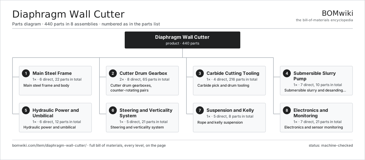
| # | Part | Qty | What it does |
|---|---|---|---|
| 1 | Main Steel Frame 6 parts | 1× | Main steel frame and body |
| 2 | Cutter Drum Gearbox 8 parts | 2× | Cutter drum gearboxes, counter-rotating pairs |
| 3 | Carbide Cutting Tooling 4 parts | 1× | Carbide pick and drum tooling |
| 4 | Submersible Slurry Pump 7 parts | 1× | Submersible slurry and desanding pump |
| 5 | Hydraulic Power and Umbilical 6 parts | 1× | Hydraulic power and umbilical |
| 6 | Steering and Verticality System 5 parts | 1× | Steering and verticality system |
| 7 | Suspension and Kelly 5 parts | 1× | Rope and kelly suspension |
| 8 | Electronics and Monitoring 7 parts | 1× | Electronics and sensor monitoring |
3D model
No 3D model yet. Have a CAD file of this? Add a 3D model — STL renders right on this page; STEP, FreeCAD, and OpenSCAD sources are welcome too (openly licensed, like all 3D models on BOMwiki).
Build & assembly graph
expand / collapse · shared sub-assemblies converge · links to related products · est. labourTap an assembly to expand/collapse · tap a part to open it · use “Open page” for any node · drag to pan, scroll to zoom.
Bill of materials for Diaphragm Wall Cutter
8 top-level lines · 81 rows shown · 440 parts total · indented to 3 levels| # | Item / sub-assembly | Part no. | Qty/assy | Ext. qty | Parts | Type |
|---|---|---|---|---|---|---|
| 1 | Main Steel Frame 6 parts | diaphragm-wall-cutter-frame | 1× | 1 | 22 | assembly |
| 1.1 | Side Main Plate | diaphragm-wall-cutter-frame-mainplate | 2× | 2 | · | part |
| 1.2 | Cross Member | diaphragm-wall-cutter-frame-crossmember | 4× | 4 | · | part |
| 1.3 | Guide Plate | diaphragm-wall-cutter-frame-guide-plate | 4× | 4 | · | part |
| 1.4 | Spoil Deflector | diaphragm-wall-cutter-frame-deflector | 2× | 2 | · | part |
| 1.5 | Lifting Eye | diaphragm-wall-cutter-frame-lift-eye | 4× | 4 | · | part |
| 1.6 | Fastener Set | fastener-set | 6× | 6 | · | part |
| 2 | Cutter Drum Gearbox 8 parts | diaphragm-wall-cutter-drum-gearbox | 2× | 2 | 65 | assembly |
| 2.1 | Gearbox Housing | gearbox-housing | 1× | 2 | · | part |
| 2.2 | Hydraulic Drum Motor 4 parts | diaphragm-wall-cutter-drum-motor | 1× | 2 | 10 | assembly |
| 2.2.1 | Radial Piston | diaphragm-wall-cutter-motor-piston | 7× | 14 | · | part |
| 2.2.2 | Cam Ring | diaphragm-wall-cutter-motor-camring | 1× | 2 | · | part |
| 2.2.3 | Valve Plate | diaphragm-wall-cutter-motor-valveplate | 1× | 2 | · | part |
| 2.2.4 | O-Ring Set | oring-set | 1× | 2 | · | part |
| 2.3 | Planetary Stage 4 parts | diaphragm-wall-cutter-planetary-stage | 2× | 4 | 8 | assembly |
| 2.3.1 | Sun Gear | diaphragm-wall-cutter-sun-gear | 1× | 4 | · | part |
| 2.3.2 | Helical Gear Pair | gear-pair | 3× | 12 | · | part |
| 2.3.3 | Planet Carrier | diaphragm-wall-cutter-planet-carrier | 1× | 4 | · | part |
| 2.3.4 | Ball Bearing | ball-bearing | 3× | 12 | · | part |
| 2.4 | Drum Output Shaft | diaphragm-wall-cutter-output-shaft | 1× | 2 | · | part |
| 2.5 | Cutter Drum 3 parts | diaphragm-wall-cutter-cutter-drum | 1× | 2 | 29 | assembly |
| 2.5.1 | Drum Shell | diaphragm-wall-cutter-drum-shell | 1× | 2 | · | part |
| 2.5.2 | Pick Block | diaphragm-wall-cutter-pick-block | 24× | 48 | · | part |
| 2.5.3 | Flush Port | diaphragm-wall-cutter-flush-port | 4× | 8 | · | part |
| 2.6 | Ball Bearing | ball-bearing | 4× | 8 | · | part |
| 2.7 | Oil Seal | oil-seal | 3× | 6 | · | part |
| 2.8 | O-Ring Set | oring-set | 1× | 2 | · | part |
| 3 | Carbide Cutting Tooling 4 parts | diaphragm-wall-cutter-cutting-tooling | 1× | 1 | 216 | assembly |
| 3.1 | Carbide Pick | diaphragm-wall-cutter-pick | 96× | 96 | · | part |
| 3.2 | Side Gauge Cutter | diaphragm-wall-cutter-side-cutter | 8× | 8 | · | part |
| 3.3 | Pick Retainer | diaphragm-wall-cutter-pick-retainer | 96× | 96 | · | part |
| 3.4 | Wear Button | diaphragm-wall-cutter-wear-button | 16× | 16 | · | part |
| 4 | Submersible Slurry Pump 7 parts | diaphragm-wall-cutter-slurry-pump | 1× | 1 | 10 | assembly |
| 4.1 | Slurry Impeller | diaphragm-wall-cutter-pump-impeller | 1× | 1 | · | part |
| 4.2 | Pump Volute | diaphragm-wall-cutter-pump-volute | 1× | 1 | · | part |
| 4.3 | Pump Drive Motor | diaphragm-wall-cutter-pump-motor | 1× | 1 | · | part |
| 4.4 | Pump Intake | diaphragm-wall-cutter-pump-intake | 1× | 1 | · | part |
| 4.5 | Wear Liner | diaphragm-wall-cutter-pump-wear-liner | 2× | 2 | · | part |
| 4.6 | Ball Bearing | ball-bearing | 2× | 2 | · | part |
| 4.7 | Oil Seal | oil-seal | 2× | 2 | · | part |
| 5 | Hydraulic Power and Umbilical 6 parts | diaphragm-wall-cutter-hydraulic-power | 1× | 1 | 12 | assembly |
| 5.1 | Valve Manifold | diaphragm-wall-cutter-manifold | 1× | 1 | · | part |
| 5.2 | Hose Reel 3 parts | diaphragm-wall-cutter-hose-reel | 1× | 1 | 3 | assembly |
| 5.2.1 | Reel Drum | diaphragm-wall-cutter-reel-drum | 1× | 1 | · | part |
| 5.2.2 | Rotary Swivel | diaphragm-wall-cutter-reel-swivel | 1× | 1 | · | part |
| 5.2.3 | Reel Drive | diaphragm-wall-cutter-reel-drive | 1× | 1 | · | part |
| 5.3 | Umbilical | diaphragm-wall-cutter-umbilical | 1× | 1 | · | part |
| 5.4 | Accumulator | diaphragm-wall-cutter-accumulator | 2× | 2 | · | part |
| 5.5 | Pressure Sensor | pressure-sensor | 3× | 3 | · | part |
| 5.6 | O-Ring Set | oring-set | 2× | 2 | · | part |
| 6 | Steering and Verticality System 5 parts | diaphragm-wall-cutter-steering | 1× | 1 | 21 | assembly |
| 6.1 | Steering Flap | diaphragm-wall-cutter-steering-flap | 4× | 4 | · | part |
| 6.2 | Flap Cylinder 3 parts | diaphragm-wall-cutter-flap-cylinder | 4× | 4 | 3 | assembly |
| 6.2.1 | Cylinder Barrel | diaphragm-wall-cutter-cylinder-barrel | 1× | 4 | · | part |
| 6.2.2 | Piston Rod | diaphragm-wall-cutter-cylinder-rod | 1× | 4 | · | part |
| 6.2.3 | O-Ring Set | oring-set | 1× | 4 | · | part |
| 6.3 | Inclinometer | diaphragm-wall-cutter-inclinometer | 2× | 2 | · | part |
| 6.4 | Steering Valve | diaphragm-wall-cutter-steering-valve | 1× | 1 | · | part |
| 6.5 | Pressure Sensor | pressure-sensor | 2× | 2 | · | part |
| 7 | Suspension and Kelly 5 parts | diaphragm-wall-cutter-suspension | 1× | 1 | 8 | assembly |
| 7.1 | Kelly Adapter | diaphragm-wall-cutter-kelly-adapter | 1× | 1 | · | part |
| 7.2 | Rope Socket | diaphragm-wall-cutter-rope-socket | 2× | 2 | · | part |
| 7.3 | Shock Absorber | diaphragm-wall-cutter-shock-absorber | 2× | 2 | · | part |
| 7.4 | Load Pin | diaphragm-wall-cutter-load-pin | 1× | 1 | · | part |
| 7.5 | Fastener Set | fastener-set | 2× | 2 | · | part |
| 8 | Electronics and Monitoring 7 parts | diaphragm-wall-cutter-electronics | 1× | 1 | 21 | assembly |
| 8.1 | Subsea Controller 5 parts | diaphragm-wall-cutter-controller | 1× | 1 | 6 | assembly |
| 8.1.1 | Microcontroller | mcu | 1× | 1 | · | part |
| 8.1.2 | Bare PCB | pcb-bare | 1× | 1 | · | part |
| 8.1.3 | SMD Passive (R/C/L) | smd-passives | 1× | 1 | · | part |
| 8.1.4 | Relay | relay | 2× | 2 | · | part |
| 8.1.5 | Pressure Housing | diaphragm-wall-cutter-pressure-housing | 1× | 1 | · | part |
| 8.2 | Cab Display 3 parts | diaphragm-wall-cutter-cab-display | 1× | 1 | 3 | assembly |
| 8.2.1 | LCD Panel | lcd-panel | 1× | 1 | · | part |
| 8.2.2 | Microcontroller | mcu | 1× | 1 | · | part |
| 8.2.3 | Power Supply | power-supply | 1× | 1 | · | part |
| 8.3 | Flow Meter | diaphragm-wall-cutter-flow-meter | 1× | 1 | · | part |
| 8.4 | Depth Encoder | diaphragm-wall-cutter-depth-encoder | 1× | 1 | · | part |
| 8.5 | Pressure Sensor | pressure-sensor | 2× | 2 | · | part |
| 8.6 | Wire Bundle | wire-bundle | 2× | 2 | · | part |
| 8.7 | Connector | connector | 6× | 6 | · | part |
Related products
same domain, ranked by shared parts Asphalt Recycler
226 parts · shares 11 with this page
Bridge Form Traveler
405 parts · shares 11 with this page
Asphalt Recycler
226 parts · shares 11 with this page
Bridge Form Traveler
405 parts · shares 11 with this page
 Bridge Girder Launching Gantry
1,542 parts · shares 11 with this page
Bridge Girder Launching Gantry
1,542 parts · shares 11 with this page
 Drilling Rig Truck
310 parts · shares 11 with this page
Drilling Rig Truck
310 parts · shares 11 with this page
 Flat-Top Tower Crane
358 parts · shares 11 with this page
Flat-Top Tower Crane
358 parts · shares 11 with this page
 Guardrail Installation Rig
320 parts · shares 11 with this page
Guardrail Installation Rig
320 parts · shares 11 with this page
Sourcing: possible vendors
Prices, MOQ, and lead times are algorithmic estimates, not quotes, and not claims about these companies. Company mappings are curated by keyword; est. price band $15k–$2M. How estimates work| Vendor | HQ | Specialty | MOQ | Lead time |
|---|---|---|---|---|
| caterpillar.com ↗ | Irving, US | Construction & mining equipment | made to order | 16–28 wks |
|
🇯🇵Komatsu
komatsu.com ↗
|
Tokyo, JP | Construction & mining equipment | made to order | 16–28 wks |
|
🇸🇪Volvo CE
volvoce.com ↗
|
Gothenburg, SE | Construction equipment | made to order | 16–28 wks |
|
🇨🇭Liebherr
liebherr.com ↗
|
Bulle, CH | Cranes & heavy equipment | made to order | 16–28 wks |
|
🇨🇳XCMG
xcmg.com ↗
|
Xuzhou, CN | Construction machinery | made to order | 16–28 wks |
1,046-word article