Cold Milling Machine (Road Planer)
ProductOverview
A cold milling machine removes a controlled thickness of asphalt or concrete pavement so a road can be resurfaced to the correct level. "Cold" means it grinds the existing surface at ambient temperature rather than heating it, producing reclaimable millings that are recycled into new asphalt. The machine sets the depth and cross-slope of the cut precisely, leaving a clean, textured surface ready for a fresh overlay.
Two systems define it: the Milling Drum Unit that does the cutting, and the Conveyor System that clears the millings continuously so the cut never chokes. A turbocharged Diesel Engine supplies the large power the drum demands.
How it works
The heart of the machine is the Milling Drum Unit, a heavy steel drum carrying a spiral pattern of replaceable carbide picks. Engine power reaches it through the Drum Drive, a belt feeding a reduction gearbox, because the drum needs high torque at a modest speed. As the picks strike the pavement they fracture it into millings; each pick rotates freely in its holder so it self-sharpens and wears evenly, and worn picks are knocked out and replaced individually.
The machine rides on four crawler Tracks & Leg Columns units mounted on hydraulic leg columns. Raising or lowering the legs sets the milling depth, and driving the front and rear legs to different heights sets the cross-slope, both held automatically by the Machine Control grade system referencing a stringline, the existing surface, or a laser plane.
Millings are scooped from the drum chamber by the Conveyor System primary belt and handed to a long front discharge belt that throws them into a truck driving ahead of the machine; the discharge belt slews to either side to follow the truck. The Water Spray System system continuously wets the drum to cool the carbide tips and knock down dust. All travel, leg, conveyor, and steering motion is powered by the Hydraulic System, with the operator working from a quiet, isolated Operator Cab that has direct sightlines to the cutting edge.
Cold Milling Machine (Road Planer) parts and their functions
9 top-level parts · 824 parts in total · full bill of materials below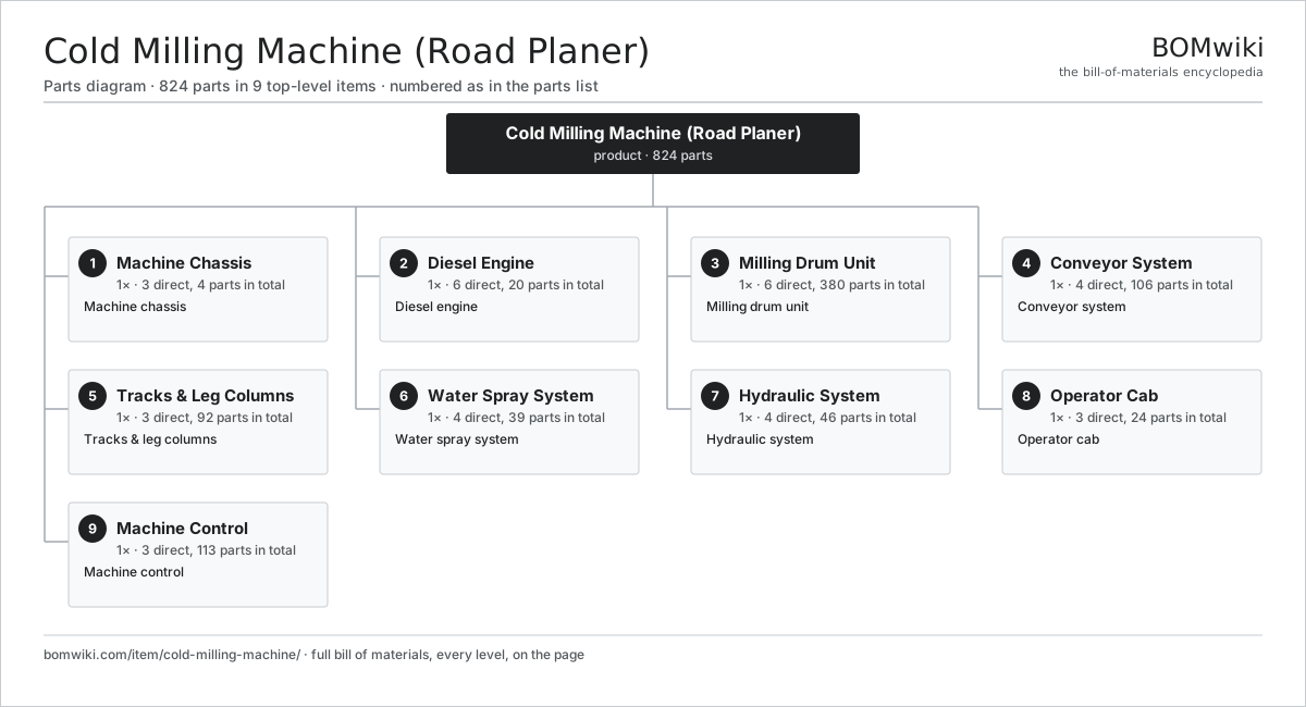
| # | Part | Qty | What it does |
|---|---|---|---|
| 1 | Machine Chassis 3 parts | 1× | Machine chassis |
| 2 | Diesel Engine 6 parts | 1× | Diesel engine |
| 3 | Milling Drum Unit 6 parts | 1× | Milling drum unit |
| 4 | Conveyor System 4 parts | 1× | Conveyor system |
| 5 | Tracks & Leg Columns 3 parts | 1× | Tracks & leg columns |
| 6 | Water Spray System 4 parts | 1× | Water spray system |
| 7 | Hydraulic System 4 parts | 1× | Hydraulic system |
| 8 | Operator Cab 3 parts | 1× | Operator cab |
| 9 | Machine Control 3 parts | 1× | Machine control |
Diagrams & photos


3D model
No 3D model yet. Have a CAD file of this? Add a 3D model. STL renders right on this page; STEP, FreeCAD, and OpenSCAD sources are welcome too (openly licensed, like all 3D models on BOMwiki).
Build & assembly graph
expand / collapse · shared sub-assemblies converge · links to related products · est. labourTap an assembly to expand/collapse · tap a part to open it · use “Open page” for any node · drag to pan, scroll to zoom.
Bill of materials for Cold Milling Machine (Road Planer)
9 top-level lines · 108 rows shown · 824 parts total · indented to 3 levels| # | Item / sub-assembly | Part no. | Qty/assy | Ext. qty | Parts | Type |
|---|---|---|---|---|---|---|
| 1 | Machine Chassis 3 parts | cmm-chassis | 1× | 1 | 4 | assembly |
| 1.1 | Main Frame | cmm-main-frame | 1× | 1 | · | part |
| 1.2 | Side Plate | cmm-side-plate | 2× | 2 | · | part |
| 1.3 | Fastener Set | fastener-set | 1× | 1 | · | part |
| 2 | Diesel Engine 6 parts | cmm-engine | 1× | 1 | 20 | assembly |
| 2.1 | Engine Block | cmm-engine-block | 1× | 1 | · | part |
| 2.2 | Piston | cmm-piston | 6× | 6 | · | part |
| 2.3 | Crankshaft | cmm-crankshaft | 1× | 1 | · | part |
| 2.4 | Turbocharger | cmm-turbo | 1× | 1 | · | part |
| 2.5 | Fuel System 3 parts | cmm-fuel-system | 1× | 1 | 8 | assembly |
| 2.5.1 | Injection Pump | cmm-injection-pump | 1× | 1 | · | part |
| 2.5.2 | Fuel Injector | cmm-injector | 6× | 6 | · | part |
| 2.5.3 | Fuel Filter | cmm-fuel-filter | 1× | 1 | · | part |
| 2.6 | Engine Cooling 3 parts | cmm-cooling | 1× | 1 | 3 | assembly |
| 2.6.1 | Radiator | radiator | 1× | 1 | · | part |
| 2.6.2 | Coolant Pump | coolant-pump | 1× | 1 | · | part |
| 2.6.3 | Hydraulic Cooling Fan | cmm-cooling-fan | 1× | 1 | · | part |
| 3 | Milling Drum Unit 6 parts | cmm-milling-unit | 1× | 1 | 380 | assembly |
| 3.1 | Milling Drum 4 parts | cmm-milling-drum | 1× | 1 | 6 | assembly |
| 3.1.1 | Drum Tube | cmm-drum-tube | 1× | 1 | · | part |
| 3.1.2 | Spiral Flight | cmm-drum-flight | 1× | 1 | · | part |
| 3.1.3 | Ball Bearing | ball-bearing | 2× | 2 | · | part |
| 3.1.4 | Oil Seal | oil-seal | 2× | 2 | · | part |
| 3.2 | Carbide Cutting Pick | cmm-carbide-pick | 180× | 180 | · | part |
| 3.3 | Pick Holder | cmm-pick-holder | 180× | 180 | · | part |
| 3.4 | Drum Housing | cmm-drum-housing | 1× | 1 | · | part |
| 3.5 | Drum Drive 6 parts | cmm-drum-drive | 1× | 1 | 12 | assembly |
| 3.5.1 | Drive Belt | cmm-drive-belt | 1× | 1 | · | part |
| 3.5.2 | Belt Pulley | cmm-belt-pulley | 2× | 2 | · | part |
| 3.5.3 | Gearbox Housing | gearbox-housing | 1× | 1 | · | part |
| 3.5.4 | Helical Gear Pair | gear-pair | 2× | 2 | · | part |
| 3.5.5 | Ball Bearing | ball-bearing | 4× | 4 | · | part |
| 3.5.6 | Oil Seal | oil-seal | 2× | 2 | · | part |
| 3.6 | Rear Moldboard | cmm-moldboard | 1× | 1 | · | part |
| 4 | Conveyor System 4 parts | cmm-conveyor-system | 1× | 1 | 106 | assembly |
| 4.1 | Primary Conveyor 3 parts | cmm-primary-conveyor | 1× | 1 | 20 | assembly |
| 4.1.1 | Conveyor Belt | cmm-conveyor-belt | 1× | 1 | · | part |
| 4.1.2 | Conveyor Roller | cmm-conveyor-roller | 18× | 18 | · | part |
| 4.1.3 | Conveyor Frame | cmm-conveyor-frame | 1× | 1 | · | part |
| 4.2 | Discharge Conveyor 3 parts | cmm-discharge-conveyor | 1× | 1 | 24 | assembly |
| 4.2.1 | Conveyor Belt | cmm-conveyor-belt | 1× | 1 | · | part |
| 4.2.2 | Conveyor Roller | cmm-conveyor-roller | 22× | 22 | · | part |
| 4.2.3 | Conveyor Frame | cmm-conveyor-frame | 1× | 1 | · | part |
| 4.3 | Conveyor Drive Motor 4 parts | cmm-conveyor-motor | 2× | 2 | 25 | assembly |
| 4.3.1 | Stator Assembly 3 parts + deeper › | stator-assembly | 1× | 2 | 3 | assembly |
| 4.3.2 | Rotor Assembly 4 parts + deeper › | rotor-assembly | 1× | 2 | 19 | assembly |
| 4.3.3 | Motor Housing | motor-housing | 1× | 2 | · | part |
| 4.3.4 | Ball Bearing | ball-bearing | 2× | 4 | · | part |
| 4.4 | Slew Cylinder 4 parts | cmm-slew-cylinder | 2× | 2 | 6 | assembly |
| 4.4.1 | Cylinder Barrel | cmm-cyl-barrel | 1× | 2 | · | part |
| 4.4.2 | Cylinder Rod | cmm-cyl-rod | 1× | 2 | · | part |
| 4.4.3 | O-Ring Set | oring-set | 2× | 4 | · | part |
| 4.4.4 | Oil Seal | oil-seal | 2× | 4 | · | part |
| 5 | Tracks & Leg Columns 3 parts | cmm-track-leg | 1× | 1 | 92 | assembly |
| 5.1 | Crawler Track 4 parts | cmm-track | 4× | 4 | 16 | assembly |
| 5.1.1 | Track Chain | cmm-track-chain | 1× | 4 | · | part |
| 5.1.2 | Track Drive Motor 5 parts + deeper › | cmm-track-motor | 1× | 4 | 8 | assembly |
| 5.1.3 | Drive Sprocket | cmm-track-sprocket | 1× | 4 | · | part |
| 5.1.4 | Track Roller | cmm-track-roller | 6× | 24 | · | part |
| 5.2 | Leg Column | cmm-leg-column | 4× | 4 | · | part |
| 5.3 | Leg Lift Cylinder 4 parts | cmm-leg-cylinder | 4× | 4 | 6 | assembly |
| 5.3.1 | Cylinder Barrel | cmm-cyl-barrel | 1× | 4 | · | part |
| 5.3.2 | Cylinder Rod | cmm-cyl-rod | 1× | 4 | · | part |
| 5.3.3 | O-Ring Set | oring-set | 2× | 8 | · | part |
| 5.3.4 | Oil Seal | oil-seal | 2× | 8 | · | part |
| 6 | Water Spray System 4 parts | cmm-water-spray | 1× | 1 | 39 | assembly |
| 6.1 | Water Tank | cmm-water-tank | 1× | 1 | · | part |
| 6.2 | Spray Pump 4 parts | cmm-water-pump | 1× | 1 | 25 | assembly |
| 6.2.1 | Stator Assembly 3 parts + deeper › | stator-assembly | 1× | 1 | 3 | assembly |
| 6.2.2 | Rotor Assembly 4 parts + deeper › | rotor-assembly | 1× | 1 | 19 | assembly |
| 6.2.3 | Pump Impeller | cmm-pump-impeller | 1× | 1 | · | part |
| 6.2.4 | Ball Bearing | ball-bearing | 2× | 2 | · | part |
| 6.3 | Spray Nozzle | cmm-spray-nozzle | 12× | 12 | · | part |
| 6.4 | Water Filter | cmm-water-filter | 1× | 1 | · | part |
| 7 | Hydraulic System 4 parts | cmm-hydraulic-system | 1× | 1 | 46 | assembly |
| 7.1 | Hydraulic Pump 4 parts | cmm-hyd-pump | 3× | 3 | 7 | assembly |
| 7.1.1 | Pump Rotating Group | cmm-pump-rotating-group | 1× | 3 | · | part |
| 7.1.2 | Ball Bearing | ball-bearing | 2× | 6 | · | part |
| 7.1.3 | O-Ring Set | oring-set | 2× | 6 | · | part |
| 7.1.4 | Oil Seal | oil-seal | 2× | 6 | · | part |
| 7.2 | Valve Bank 3 parts | cmm-valve-bank | 1× | 1 | 23 | assembly |
| 7.2.1 | Spool Valve | cmm-spool-valve | 10× | 10 | · | part |
| 7.2.2 | Relay | relay | 8× | 8 | · | part |
| 7.2.3 | O-Ring Set | oring-set | 5× | 5 | · | part |
| 7.3 | Hydraulic Reservoir | cmm-hyd-tank | 1× | 1 | · | part |
| 7.4 | Hydraulic Oil Cooler | cmm-hyd-cooler | 1× | 1 | · | part |
| 8 | Operator Cab 3 parts | cmm-cab | 1× | 1 | 24 | assembly |
| 8.1 | Seat Assembly 5 parts | seat-assembly | 1× | 1 | 7 | assembly |
| 8.1.1 | Seat Frame | seat-frame | 1× | 1 | · | part |
| 8.1.2 | Seat Foam | seat-foam | 2× | 2 | · | part |
| 8.1.3 | Seat Cover | seat-cover | 1× | 1 | · | part |
| 8.1.4 | Seat Motor | seat-motor | 2× | 2 | · | part |
| 8.1.5 | Seat Heater Mat | seat-heater | 1× | 1 | · | part |
| 8.2 | Control Console 5 parts | cmm-console | 1× | 1 | 16 | assembly |
| 8.2.1 | Bare PCB | pcb-bare | 1× | 1 | · | part |
| 8.2.2 | Microcontroller | mcu | 1× | 1 | · | part |
| 8.2.3 | LCD Panel | lcd-panel | 1× | 1 | · | part |
| 8.2.4 | Touch Digitizer | touch-digitizer | 1× | 1 | · | part |
| 8.2.5 | Console Switch | cmm-console-switch | 12× | 12 | · | part |
| 8.3 | Cab Shell | cmm-cab-shell | 1× | 1 | · | part |
| 9 | Machine Control 3 parts | cmm-control | 1× | 1 | 113 | assembly |
| 9.1 | Grade Control Module 4 parts | cmm-control-module | 1× | 1 | 110 | assembly |
| 9.1.1 | Bare PCB | pcb-bare | 1× | 1 | · | part |
| 9.1.2 | Microcontroller | mcu | 1× | 1 | · | part |
| 9.1.3 | Connector | connector | 8× | 8 | · | part |
| 9.1.4 | SMD Passive (R/C/L) | smd-passives | 100× | 100 | · | part |
| 9.2 | Grade Reference Sensor | cmm-grade-sensor | 2× | 2 | · | part |
| 9.3 | Cross-Slope Sensor | cmm-slope-sensor | 1× | 1 | · | part |
Something wrong in this list? Report a problem with this BOM.
Related products
same domain, ranked by shared parts Rough Terrain Crane
558 parts · shares 25 with this page
 Soil Stabilizer / Reclaimer
166 parts · shares 25 with this page
 Tunnel Boring Machine
46,929 parts · shares 24 with this page
Pile Driver
519 parts · shares 25 with this page
 Pile Driving Rig
530 parts · shares 23 with this page
 Excavator
11,218 parts · shares 24 with this page
Sourcing: possible vendors
Browse the supplier directory → Prices, MOQ, and lead times are algorithmic estimates, not quotes, and not claims about these companies. Company mappings are curated by keyword; est. price band $15k–$2M. How estimates work| Vendor | HQ | Specialty | MOQ | Lead time |
|---|---|---|---|---|
| caterpillar.com ↗ | Irving, US | Construction & mining equipment | made to order | 16–28 wks |
|
🇯🇵Komatsu
komatsu.com ↗
|
Tokyo, JP | Construction & mining equipment | made to order | 16–28 wks |
|
🇸🇪Volvo CE
volvoce.com ↗
|
Gothenburg, SE | Construction equipment | made to order | 16–28 wks |
|
🇨🇭Liebherr
liebherr.com ↗
|
Bulle, CH | Cranes & heavy equipment | made to order | 16–28 wks |
|
🇨🇳XCMG
xcmg.com ↗
|
Xuzhou, CN | Construction machinery | made to order | 16–28 wks |
342-word article