Road Grader
ProductOverview
A motor grader, often called a road grader or simply a blade, is a long six-wheeled machine built around a single task: shaping a surface to a precise grade and cross-slope. Its Moldboard sits between the front and rear axles rather than at one end, and that mid-mounted position is the whole point. With the blade midway along a 8-9 m wheelbase, any vertical movement of the front or rear wheels is averaged out before it reaches the cutting edge, so the blade rides far steadier than a dozer blade hung off the nose. The operator uses this stability to cut a road base flat to within a few millimetres, set the camber that drains water off a highway, trim ditches, mix and spread material, and put a fine finish on gravel and earth.
The machine is articulated. A Front Frame carries the blade and reaches forward to a leaning steer axle, while a Rear Frame holds the engine and the driven tandem, the two joined by the Articulation Joint. Operating weight runs 14-25 t, and a typical grader is a 6x4: two steer wheels in front, four driven wheels on the rear tandem.
Frames and Articulation
The Front Main Beam is a curved high-tensile steel box section, arched upward so the Blade Circle and blade have room to lift and shift beneath it. At its nose a Drawbar Ball Joint ball joint carries the Drawbar, the A-frame that tows the whole blade carriage. A bolt-on Front Counterweight adds mass over the steer axle so the front stays planted.
The Articulation Hinge Pin runs on tapered roller bearings and takes every bit of steering reaction between the frames. Two Articulation Cylinder units swing the front frame. Articulation does two things a single rigid frame cannot. It tightens the turning circle for headland turns, and it lets the machine crab, offsetting the rear wheels so they run on finished ground while the front frame and blade reach out over a ditch or soft shoulder. A Articulation Lock Bar bar pins the frames straight for transport.
Blade Group
The grading work happens at the Moldboard & Circle Group. The Blade Circle is a toothed ring 1.4-1.8 m across slung under the drawbar, and the Circle Drive turns it through a full 360 degrees, holding the chosen blade angle against the cutting load. Bolted to the circle is the Moldboard, a curved steel blade 3.7-4.9 m wide that shears material loose, rolls it along the curve, and casts it to one side. Along its bottom runs a replaceable Cutting Edge, with a hardened Blade End Bit at each corner where wear is worst.
Five hydraulic motions position the blade. A pair of Blade Lift Cylinder units, one per side, set the height of each end independently, which is how the operator dials in cross-slope; the blade can rise about 430-510 mm above ground or cut 700-790 mm below it. The Circle Side-Shift Cylinder slides the whole circle sideways across the frame, while the Blade Side-Shift Cylinder slides the moldboard along the circle so the blade can reach well outside the wheel track for ditch and bank work. The Blade Tip Cylinder rolls the top of the blade forward or back to change the angle of attack, steeper to cut hard ground, laid back to spread and finish. A set of Moldboard Slide Shoe wear shoes carries the rubbing load as the blade shifts.
Powertrain
Power comes from a Turbo Diesel Engine, an inline-six turbo diesel of 120-220 kW, often with a variable horsepower curve that gives more power in the higher gears. Cooling is handled by the Cooling Module with a variable-speed hydraulic fan sized for the long low-speed passes grading demands, and exhaust runs through the Exhaust Aftertreatment unit to meet Stage V and Tier 4 Final limits. The Pump Drive Gearbox splits flywheel power among the hydraulic pumps.
Travel runs through the Transmission Group. A Torque Converter multiplies torque from rest and locks up for efficient steady work, feeding a Powershift Transmission powershift gearbox with six to eight forward ratios so the operator can match ground speed exactly to cut depth and material. A Drive Propshaft carries the drive back to the tandem case, and a spring-applied Parking Brake holds the machine when idle.
Axles and Steering
The Leaning Steer Front Axle is a non-driven leaning steer axle. Its Front Axle Beam oscillates on a centre trunnion, and a Wheel Lean Cylinder tilts both Front Steer Wheel units up to 18 degrees. Leaning the wheels into the work counters the side-thrust the angled blade pushes into the machine, keeping it tracking straight instead of crabbing sideways. Two Steering Cylinder units turn the Steering Knuckle joints.
Drive and weight sit on the Rear Tandem Drive Axle. Each Tandem Walking Beam is a sealed walking beam pivoting at its centre, with a Tandem Drive Chain inside carrying torque to the front and rear wheel sprockets so both Rear Drive Wheel units keep gripping over bumps. A Tandem Differential, usually lockable, splits torque between the sides, a Planetary Wheel Hub gives the final reduction at each wheel, and a Wet Multi-Disc Brake of oil-immersed discs stops each wheel end.
Attachments and Hydraulics
Ahead of the blade, the Scarifier & Ripper Group breaks ground the moldboard alone cannot. A Scarifier Cylinder lowers a toolbar carrying up to nine Scarifier Shank units, each holding a replaceable Scarifier Tooth that rips through hardpan, compacted gravel, and old asphalt so the blade can then trim it.
Every implement motion is hydraulic and needs fine control. The Load-Sensing Main Pump is a load-sensing piston pump matching flow to demand so several blade functions move at once without robbing each other, while a separate Steering Pump keeps steering and lean at full priority. Oil is metered by the Proportional Valve Bank, and several Pressure Sensor units feed the controllers.
Cab and Grade Control
The Cab Structure is a certified ROPS-FOPS structure with wide Cab Glazing and a low sill so the operator can watch the cutting edge. A swivelling Suspension Seat and a Control Console of joysticks or levers run the many blade axes. Modern graders automate much of the work: a Grade Controller reads a Cross-Slope Sensor and a GNSS Receiver & Mast and drives the blade lift cylinders to hold a digital design surface, taking the operator off constant manual correction. A Wire Bundle ties it together and an LCD Panel shows grade and status.
Road Grader parts and their functions
12 top-level parts · 143 parts in total · full bill of materials below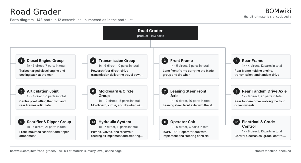
| # | Part | Qty | What it does |
|---|---|---|---|
| 1 | Diesel Engine Group 6 parts | 1× | Turbocharged diesel engine and cooling pack at the rear |
| 2 | Transmission Group 6 parts | 1× | Powershift or direct-drive transmission delivering travel power |
| 3 | Front Frame 5 parts | 1× | Long front frame carrying the blade group and drawbar |
| 4 | Rear Frame 4 parts | 1× | Rear frame holding engine, transmission, and tandem drive |
| 5 | Articulation Joint 4 parts | 1× | Centre pivot letting the front and rear frames articulate |
| 6 | Moldboard & Circle Group 10 parts | 1× | Moldboard, circle, and drawbar with their lift and shift cylinders |
| 7 | Leaning Steer Front Axle 6 parts | 1× | Leaning steer front axle with the steering linkage |
| 8 | Rear Tandem Drive Axle 8 parts | 1× | Rear tandem drive walking the four driven wheels |
| 9 | Scarifier & Ripper Group 5 parts | 1× | Front-mounted scarifier and ripper attachment |
| 10 | Hydraulic System 7 parts | 1× | Pumps, valves, and reservoir feeding all implement and steering circuits |
| 11 | Operator Cab 6 parts | 1× | ROPS-FOPS operator cab with implement and steering controls |
| 12 | Electrical & Grade Control 8 parts | 1× | Control electronics, grade-control sensors, and lighting harness |
3D model
No 3D model yet. Have a CAD file of this? Add a 3D model — STL renders right on this page; STEP, FreeCAD, and OpenSCAD sources are welcome too (openly licensed, like all 3D models on BOMwiki).
Build & assembly graph
expand / collapse · shared sub-assemblies converge · links to related products · est. labourTap an assembly to expand/collapse · tap a part to open it · use “Open page” for any node · drag to pan, scroll to zoom.
Bill of materials for Road Grader
12 top-level lines · 87 rows shown · 143 parts total · indented to 3 levels| # | Item / sub-assembly | Part no. | Qty/assy | Ext. qty | Parts | Type |
|---|---|---|---|---|---|---|
| 1 | Diesel Engine Group 6 parts | road-grader-engine-group | 1× | 1 | 7 | assembly |
| 1.1 | Turbo Diesel Engine | road-grader-engine | 1× | 1 | · | part |
| 1.2 | Cooling Module | road-grader-cooling-pack | 1× | 1 | · | part |
| 1.3 | Exhaust Aftertreatment | road-grader-aftertreatment | 1× | 1 | · | part |
| 1.4 | Diesel Fuel Tank | road-grader-fuel-tank | 1× | 1 | · | part |
| 1.5 | Pump Drive Gearbox | road-grader-pump-drive | 1× | 1 | · | part |
| 1.6 | O-Ring Set | oring-set | 2× | 2 | · | part |
| 2 | Transmission Group 6 parts | road-grader-transmission-group | 1× | 1 | 10 | assembly |
| 2.1 | Torque Converter | road-grader-torque-converter | 1× | 1 | · | part |
| 2.2 | Powershift Transmission | road-grader-transmission | 1× | 1 | · | part |
| 2.3 | Drive Propshaft | road-grader-driveline | 1× | 1 | · | part |
| 2.4 | Parking Brake | road-grader-park-brake | 1× | 1 | · | part |
| 2.5 | Helical Gear Pair | gear-pair | 2× | 2 | · | part |
| 2.6 | Oil Seal | oil-seal | 4× | 4 | · | part |
| 3 | Front Frame 5 parts | road-grader-front-frame | 1× | 1 | 5 | assembly |
| 3.1 | Front Main Beam | road-grader-front-beam | 1× | 1 | · | part |
| 3.2 | Drawbar | road-grader-drawbar | 1× | 1 | · | part |
| 3.3 | Drawbar Ball Joint | road-grader-front-frame-pivot | 1× | 1 | · | part |
| 3.4 | Front Counterweight | road-grader-counterweight | 1× | 1 | · | part |
| 3.5 | O-Ring Set | oring-set | 1× | 1 | · | part |
| 4 | Rear Frame 4 parts | road-grader-rear-frame | 1× | 1 | 12 | assembly |
| 4.1 | Rear Main Beam | road-grader-rear-beam | 1× | 1 | · | part |
| 4.2 | Powertrain Mount | road-grader-engine-mounts | 4× | 4 | · | part |
| 4.3 | Rear Ripper Interface | road-grader-ripper-mount | 1× | 1 | · | part |
| 4.4 | Sheet Metal Panel | sheet-panel | 6× | 6 | · | part |
| 5 | Articulation Joint 4 parts | road-grader-articulation-joint | 1× | 1 | 6 | assembly |
| 5.1 | Articulation Hinge Pin | road-grader-articulation-hinge | 1× | 1 | · | part |
| 5.2 | Articulation Cylinder | road-grader-articulation-cylinder | 2× | 2 | · | part |
| 5.3 | Articulation Lock Bar | road-grader-articulation-lock | 1× | 1 | · | part |
| 5.4 | Ball Bearing | ball-bearing | 2× | 2 | · | part |
| 6 | Moldboard & Circle Group 10 parts | road-grader-blade-group | 1× | 1 | 15 | assembly |
| 6.1 | Blade Circle | road-grader-circle | 1× | 1 | · | part |
| 6.2 | Circle Drive | road-grader-circle-drive | 1× | 1 | · | part |
| 6.3 | Moldboard | road-grader-moldboard | 1× | 1 | · | part |
| 6.4 | Cutting Edge | road-grader-cutting-edge | 1× | 1 | · | part |
| 6.5 | Blade End Bit | road-grader-end-bit | 2× | 2 | · | part |
| 6.6 | Blade Lift Cylinder | road-grader-blade-lift-cylinder | 2× | 2 | · | part |
| 6.7 | Circle Side-Shift Cylinder | road-grader-side-shift-cylinder | 1× | 1 | · | part |
| 6.8 | Blade Side-Shift Cylinder | road-grader-blade-shift-cylinder | 1× | 1 | · | part |
| 6.9 | Blade Tip Cylinder | road-grader-blade-tip-cylinder | 1× | 1 | · | part |
| 6.10 | Moldboard Slide Shoe | road-grader-slide-rail | 4× | 4 | · | part |
| 7 | Leaning Steer Front Axle 6 parts | road-grader-front-axle | 1× | 1 | 10 | assembly |
| 7.1 | Front Axle Beam | road-grader-front-axle-beam | 1× | 1 | · | part |
| 7.2 | Wheel Lean Cylinder | road-grader-wheel-lean-cylinder | 1× | 1 | · | part |
| 7.3 | Steering Cylinder | road-grader-steering-cylinder | 2× | 2 | · | part |
| 7.4 | Steering Knuckle | road-grader-knuckle | 2× | 2 | · | part |
| 7.5 | Front Steer Wheel | road-grader-front-wheel | 2× | 2 | · | part |
| 7.6 | Ball Bearing | ball-bearing | 2× | 2 | · | part |
| 8 | Rear Tandem Drive Axle 8 parts | road-grader-tandem-axle | 1× | 1 | 25 | assembly |
| 8.1 | Tandem Walking Beam | road-grader-tandem-case | 2× | 2 | · | part |
| 8.2 | Tandem Drive Chain | road-grader-tandem-chain | 4× | 4 | · | part |
| 8.3 | Tandem Differential | road-grader-tandem-differential | 1× | 1 | · | part |
| 8.4 | Planetary Wheel Hub | road-grader-planetary-hub | 4× | 4 | · | part |
| 8.5 | Rear Drive Wheel | road-grader-rear-wheel | 4× | 4 | · | part |
| 8.6 | Wet Multi-Disc Brake | road-grader-service-brake | 4× | 4 | · | part |
| 8.7 | Helical Gear Pair | gear-pair | 2× | 2 | · | part |
| 8.8 | Oil Seal | oil-seal | 4× | 4 | · | part |
| 9 | Scarifier & Ripper Group 5 parts | road-grader-scarifier-group | 1× | 1 | 21 | assembly |
| 9.1 | Scarifier Mount Frame | road-grader-scarifier-frame | 1× | 1 | · | part |
| 9.2 | Scarifier Cylinder | road-grader-scarifier-cylinder | 1× | 1 | · | part |
| 9.3 | Scarifier Shank | road-grader-scarifier-shank | 9× | 9 | · | part |
| 9.4 | Scarifier Tooth | road-grader-scarifier-tooth | 9× | 9 | · | part |
| 9.5 | Fastener Set | fastener-set | 1× | 1 | · | part |
| 10 | Hydraulic System 7 parts | road-grader-hydraulics | 1× | 1 | 11 | assembly |
| 10.1 | Load-Sensing Main Pump | road-grader-main-pump | 1× | 1 | · | part |
| 10.2 | Steering Pump | road-grader-steering-pump | 1× | 1 | · | part |
| 10.3 | Proportional Valve Bank | road-grader-valve-bank | 1× | 1 | · | part |
| 10.4 | Hydraulic Reservoir | road-grader-hydraulic-tank | 1× | 1 | · | part |
| 10.5 | Hydraulic Hose Set | road-grader-hose-set | 1× | 1 | · | part |
| 10.6 | Pressure Sensor | pressure-sensor | 4× | 4 | · | part |
| 10.7 | O-Ring Set | oring-set | 2× | 2 | · | part |
| 11 | Operator Cab 6 parts | road-grader-cab | 1× | 1 | 6 | assembly |
| 11.1 | Cab Structure | road-grader-cab-shell | 1× | 1 | · | part |
| 11.2 | Cab Glazing | road-grader-cab-glazing | 1× | 1 | · | part |
| 11.3 | Suspension Seat | road-grader-operator-seat | 1× | 1 | · | part |
| 11.4 | Control Console | road-grader-control-console | 1× | 1 | · | part |
| 11.5 | Cab HVAC Unit | road-grader-hvac | 1× | 1 | · | part |
| 11.6 | LCD Panel | lcd-panel | 1× | 1 | · | part |
| 12 | Electrical & Grade Control 8 parts | road-grader-electrical | 1× | 1 | 15 | assembly |
| 12.1 | Vehicle Control Unit | road-grader-vehicle-ecu | 1× | 1 | · | part |
| 12.2 | Grade Controller | road-grader-grade-controller | 1× | 1 | · | part |
| 12.3 | Cross-Slope Sensor | road-grader-slope-sensor | 2× | 2 | · | part |
| 12.4 | GNSS Receiver & Mast | road-grader-gnss-receiver | 1× | 1 | · | part |
| 12.5 | Wire Bundle | wire-bundle | 1× | 1 | · | part |
| 12.6 | Lighting Set | road-grader-light-set | 1× | 1 | · | part |
| 12.7 | Microcontroller | mcu | 2× | 2 | · | part |
| 12.8 | Connector | connector | 6× | 6 | · | part |
Related products
same domain, ranked by shared parts Bridge Girder Launching Gantry
1,542 parts · shares 7 with this page
Bridge Girder Launching Gantry
1,542 parts · shares 7 with this page
 Crawler Excavator
1,241 parts · shares 7 with this page
Crawler Excavator
1,241 parts · shares 7 with this page
 Crawler Tractor
1,361 parts · shares 7 with this page
Crawler Tractor
1,361 parts · shares 7 with this page
 Drilling Rig Truck
310 parts · shares 7 with this page
Drilling Rig Truck
310 parts · shares 7 with this page
 Flat-Top Tower Crane
358 parts · shares 7 with this page
Flat-Top Tower Crane
358 parts · shares 7 with this page
Sourcing: possible vendors
Prices, MOQ, and lead times are algorithmic estimates, not quotes, and not claims about these companies. Company mappings are curated by keyword; est. price band $15k–$2M. How estimates work| Vendor | HQ | Specialty | MOQ | Lead time |
|---|---|---|---|---|
| caterpillar.com ↗ | Irving, US | Construction & mining equipment | made to order | 16–28 wks |
|
🇯🇵Komatsu
komatsu.com ↗
|
Tokyo, JP | Construction & mining equipment | made to order | 16–28 wks |
|
🇸🇪Volvo CE
volvoce.com ↗
|
Gothenburg, SE | Construction equipment | made to order | 16–28 wks |
|
🇨🇭Liebherr
liebherr.com ↗
|
Bulle, CH | Cranes & heavy equipment | made to order | 16–28 wks |
|
🇨🇳XCMG
xcmg.com ↗
|
Xuzhou, CN | Construction machinery | made to order | 16–28 wks |
1,190-word article