Wall Formwork
ProductAlso known as: panel formwork, wall shutter, concrete wall form
Overview
Wall formwork is the temporary mould that shapes and supports fresh concrete until it cures into a structural wall. Modular panel systems (the type made by Peri, Doka, MEVA and similar suppliers) build that mould from standardised steel-framed panels that clip together with wedge clamps and are held against concrete pressure by through-wall ties. A crew can erect, pour, strip and re-set the same panels many times across a project, which is why the panel system has largely replaced loose timber formwork on walls of any repetition.
The full mould is a balanced pair of wall faces. Two lines of Framed wall panel stand opposite each other at the wall thickness, the gap fixed by the Form tie assembly that passes through both faces. Everything else on the bill of materials exists to close the form at corners and ends, keep the faces flat and plumb, and let the crew work safely at the pour height.
Panels and formface
The Framed wall panel is the repeating unit, 2.7 m high by 0.9 m wide in the standard module. Its Steel panel frame profile is a closed welded perimeter, 120 mm deep, that collects concrete pressure from the face and delivers it to the ties and clamps along its edges. Inside the perimeter, several Cross stiffening rib members stiffen the panel so the face does not bow between ties. The concrete-facing surface is the Plywood formface sheet, an 18 mm phenolic film-faced birch plywood that gives a smooth fair-faced finish and survives repeated pours before it needs replacing. Each panel edge carries an Panel edge rail with clamp slots and pre-set tie holes; the holes are lined with a hardened Tie-hole sleeve so repeated tie use does not elongate them. A pair of Panel lifting eye points let the crane move whole panels or ganged panel sets.
Walls are rarely a whole number of modules long or perfectly orthogonal, so the system carries dedicated closure units. The Inside corner panel and Outside corner panel form re-entrant and external 90-degree corners; both wrap a Plywood formface sheet over a welded Corner frame profile, with the outside corner adding a Corner tie bracket to pick up corner ties. The Stop-end panel closes the vertical end of a pour or a construction joint, using a width-adjustable Stop-end frame to match the wall thickness and a Stop-end clamp to hold it against end pressure.
Ties and clamps
Form ties carry the load. As concrete is placed it behaves as a liquid, and the lateral pressure on the face rises with pour rate and depth. Panel systems are typically rated for an allowable fresh-concrete pressure of 60 to 80 kN/m2, and the Form tie assembly is what holds the two faces against that pressure. Its core is a coarse-threaded Tie rod (a Dywidag-type bar with a working load around 120 kN) passing through both panels. A Tie wing nut on each end bears on a Tie counter plate that spreads the load into the waler or frame. A Tie spacer cone at each face sets the wall thickness and leaves a tapered recess that is patched after stripping, while a lost Tie sleeve tube keeps the rod free of concrete so it can be withdrawn and reused. For water-retaining walls a Tie water stop at mid-thickness blocks the seepage path along the tie.
Panels are joined to each other by the Panel wedge clamp, a wedge connector. Its Clamp body hooks over both Panel edge rail sections and a hammer-driven Clamp wedge pulls them together, drawing the formface seam tight and aligning the faces; a Clamp jaw takes the joint-opening force and the wedge holds by friction. Where a wall length does not divide into whole modules, an Adjustable compensation clamp with a screw Clamp adjustment screw closes the gap and a Filler waling bridges the opening between two panels.
Bracing and platforms
Flatness across a run of panels comes from the Waler alignment beam, a twin-channel Waler beam section clamped across several panels by Waler clamp hooks and joined end to end by a Waler connecting pin. The waler ties the panels into one stiff line so the wall face does not step at the joints.
The whole assembly is plumbed and braced by the Push-pull prop, a raker that runs from the panel down to the slab. Its telescopic Prop tube sets the coarse length and a Prop turnbuckle makes the fine adjustment used to bring the wall to plumb. The prop connects to the panel through a Prop panel shoe and lands on a Prop base plate fixed to the floor by a Base anchor bolt. Two props per panel line, set roughly square to the wall, resist wind and the out-of-balance forces during placement.
Crews work the pour from a platform hung on the form. The Working platform bracket folds out from the panel on a Bracket arm carried by a Bracket panel hook, and supports a Platform deck board walking surface. A Guardrail post holds the Guardrail rail at top and mid height, and a Toe board stops tools dropping off the edge. The Access ladder, built from two Ladder stile rails, ten Ladder rung steps and a top Ladder hook, gives the climb from slab level. Whole panel gangs are craned in and out using the Panel lifting hook, whose forged Lifting hook body and spring Hook safety latch engage the panel lifting eyes.
Assembly and pour
A typical cycle starts by setting and clamping the first wall face on its line, fitting the corner and stop-end units, and threading the ties through the tie holes. The second face is then clamped up against it, the ties are tensioned with the wing nuts, and the walers and props bring the wall to line and plumb. Platform brackets and the ladder go on before concreting so the crew can place and vibrate from a guarded deck. Pour rate is controlled so the pressure on the panels stays within the rated 60 to 80 kN/m2. Once the concrete has gained enough strength the wing nuts are released, the wedge clamps and props are struck, and the panels are craned to the next lift, leaving only the cone recesses to patch.
Wall Formwork parts and their functions
13 top-level parts · 665 parts in total · full bill of materials below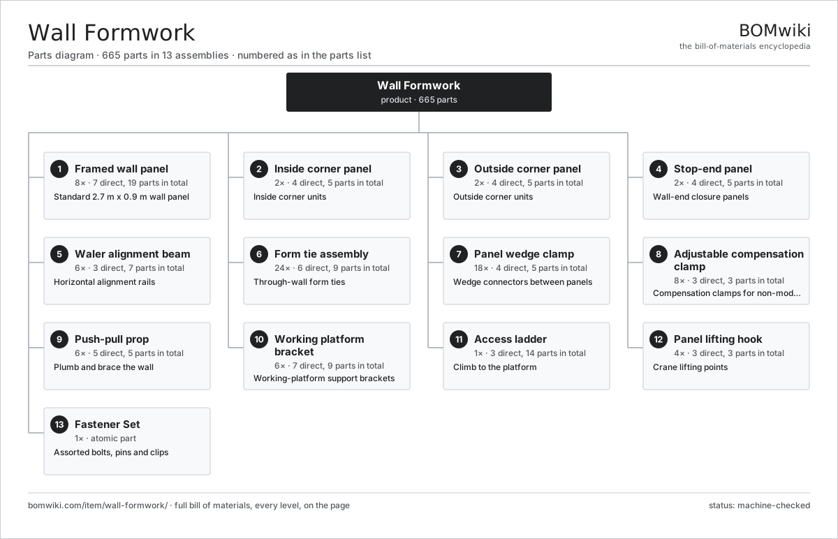
| # | Part | Qty | What it does |
|---|---|---|---|
| 1 | Framed wall panel 7 parts | 8× | Standard 2.7 m x 0.9 m wall panel |
| 2 | Inside corner panel 4 parts | 2× | Inside corner units |
| 3 | Outside corner panel 4 parts | 2× | Outside corner units |
| 4 | Stop-end panel 4 parts | 2× | Wall-end closure panels |
| 5 | Waler alignment beam 3 parts | 6× | Horizontal alignment rails |
| 6 | Form tie assembly 6 parts | 24× | Through-wall form ties |
| 7 | Panel wedge clamp 4 parts | 18× | Wedge connectors between panels |
| 8 | Adjustable compensation clamp 3 parts | 8× | Compensation clamps for non-modular gaps |
| 9 | Push-pull prop 5 parts | 6× | Plumb and brace the wall |
| 10 | Working platform bracket 7 parts | 6× | Working-platform support brackets |
| 11 | Access ladder 3 parts | 1× | Climb to the platform |
| 12 | Panel lifting hook 3 parts | 4× | Crane lifting points |
| 13 | Fastener Set | 1× | Assorted bolts, pins and clips |
Diagrams & photos


3D model
No 3D model yet. Have a CAD file of this? Add a 3D model — STL renders right on this page; STEP, FreeCAD, and OpenSCAD sources are welcome too (openly licensed, like all 3D models on BOMwiki).
Build & assembly graph
expand / collapse · shared sub-assemblies converge · links to related products · est. labourTap an assembly to expand/collapse · tap a part to open it · use “Open page” for any node · drag to pan, scroll to zoom.
Bill of materials for Wall Formwork
13 top-level lines · 66 rows shown · 665 parts total · indented to 3 levels| # | Item / sub-assembly | Part no. | Qty/assy | Ext. qty | Parts | Type |
|---|---|---|---|---|---|---|
| 1 | Framed wall panel 7 parts | wf-frame-panel | 8× | 8 | 19 | assembly |
| 1.1 | Steel panel frame profile | wf-steel-frame-profile | 1× | 8 | · | part |
| 1.2 | Cross stiffening rib | wf-cross-rib | 4× | 32 | · | part |
| 1.3 | Plywood formface sheet | wf-formface-ply | 1× | 8 | · | part |
| 1.4 | Panel edge rail | wf-edge-rail | 4× | 32 | · | part |
| 1.5 | Tie-hole sleeve | wf-tie-hole-sleeve | 6× | 48 | · | part |
| 1.6 | Panel lifting eye | wf-lifting-eye | 2× | 16 | · | part |
| 1.7 | Fastener Set | fastener-set | 1× | 8 | · | part |
| 2 | Inside corner panel 4 parts | wf-corner-panel-inside | 2× | 2 | 5 | assembly |
| 2.1 | Corner frame profile | wf-corner-profile | 1× | 2 | · | part |
| 2.2 | Plywood formface sheet | wf-formface-ply | 1× | 2 | · | part |
| 2.3 | Corner adjustment hinge | wf-corner-hinge | 2× | 4 | · | part |
| 2.4 | Fastener Set | fastener-set | 1× | 2 | · | part |
| 3 | Outside corner panel 4 parts | wf-corner-panel-outside | 2× | 2 | 5 | assembly |
| 3.1 | Corner frame profile | wf-corner-profile | 1× | 2 | · | part |
| 3.2 | Plywood formface sheet | wf-formface-ply | 1× | 2 | · | part |
| 3.3 | Corner tie bracket | wf-corner-tie-bracket | 2× | 4 | · | part |
| 3.4 | Fastener Set | fastener-set | 1× | 2 | · | part |
| 4 | Stop-end panel 4 parts | wf-stop-end-panel | 2× | 2 | 5 | assembly |
| 4.1 | Stop-end frame | wf-stop-end-frame | 1× | 2 | · | part |
| 4.2 | Plywood formface sheet | wf-formface-ply | 1× | 2 | · | part |
| 4.3 | Stop-end clamp | wf-stop-end-clamp | 2× | 4 | · | part |
| 4.4 | Fastener Set | fastener-set | 1× | 2 | · | part |
| 5 | Waler alignment beam 3 parts | wf-waler-beam | 6× | 6 | 7 | assembly |
| 5.1 | Waler beam section | wf-waler-section | 1× | 6 | · | part |
| 5.2 | Waler clamp | wf-waler-clamp | 4× | 24 | · | part |
| 5.3 | Waler connecting pin | wf-waler-end-pin | 2× | 12 | · | part |
| 6 | Form tie assembly 6 parts | wf-tie-assembly | 24× | 24 | 9 | assembly |
| 6.1 | Tie rod | wf-tie-rod | 1× | 24 | · | part |
| 6.2 | Tie wing nut | wf-wing-nut | 2× | 48 | · | part |
| 6.3 | Tie spacer cone | wf-tie-cone | 2× | 48 | · | part |
| 6.4 | Tie sleeve tube | wf-tie-sleeve | 1× | 24 | · | part |
| 6.5 | Tie water stop | wf-water-stop | 1× | 24 | · | part |
| 6.6 | Tie counter plate | wf-tie-plate | 2× | 48 | · | part |
| 7 | Panel wedge clamp 4 parts | wf-panel-clamp | 18× | 18 | 5 | assembly |
| 7.1 | Clamp body | wf-clamp-body | 1× | 18 | · | part |
| 7.2 | Clamp wedge | wf-clamp-wedge | 1× | 18 | · | part |
| 7.3 | Clamp jaw | wf-clamp-jaw | 2× | 36 | · | part |
| 7.4 | Coil Spring | coil-spring | 1× | 18 | · | part |
| 8 | Adjustable compensation clamp 3 parts | wf-adjustable-clamp | 8× | 8 | 3 | assembly |
| 8.1 | Clamp body | wf-clamp-body | 1× | 8 | · | part |
| 8.2 | Clamp adjustment screw | wf-adjust-screw | 1× | 8 | · | part |
| 8.3 | Filler waling | wf-filler-waling | 1× | 8 | · | part |
| 9 | Push-pull prop 5 parts | wf-push-pull-prop | 6× | 6 | 5 | assembly |
| 9.1 | Prop tube | wf-prop-tube | 1× | 6 | · | part |
| 9.2 | Prop turnbuckle | wf-prop-turnbuckle | 1× | 6 | · | part |
| 9.3 | Prop panel shoe | wf-prop-panel-shoe | 1× | 6 | · | part |
| 9.4 | Prop base plate | wf-prop-base-plate | 1× | 6 | · | part |
| 9.5 | Base anchor bolt | wf-base-anchor | 1× | 6 | · | part |
| 10 | Working platform bracket 7 parts | wf-platform-bracket | 6× | 6 | 9 | assembly |
| 10.1 | Bracket arm | wf-bracket-arm | 1× | 6 | · | part |
| 10.2 | Bracket panel hook | wf-bracket-hook | 1× | 6 | · | part |
| 10.3 | Platform deck board | wf-platform-deck | 2× | 12 | · | part |
| 10.4 | Guardrail post | wf-guardrail-post | 1× | 6 | · | part |
| 10.5 | Guardrail rail | wf-guardrail-rail | 2× | 12 | · | part |
| 10.6 | Toe board | wf-toe-board | 1× | 6 | · | part |
| 10.7 | Fastener Set | fastener-set | 1× | 6 | · | part |
| 11 | Access ladder 3 parts | wf-access-ladder | 1× | 1 | 14 | assembly |
| 11.1 | Ladder stile | wf-ladder-stile | 2× | 2 | · | part |
| 11.2 | Ladder rung | wf-ladder-rung | 10× | 10 | · | part |
| 11.3 | Ladder hook | wf-ladder-hook | 2× | 2 | · | part |
| 12 | Panel lifting hook 3 parts | wf-lifting-hook | 4× | 4 | 3 | assembly |
| 12.1 | Lifting hook body | wf-hook-body | 1× | 4 | · | part |
| 12.2 | Hook safety latch | wf-hook-latch | 1× | 4 | · | part |
| 12.3 | Coil Spring | coil-spring | 1× | 4 | · | part |
| 13 | Fastener Set | fastener-set | 1× | 1 | · | part |
Related products
same domain, ranked by shared parts Articulated Haul Truck
128 parts · shares 1 with this page
Articulated Haul Truck
128 parts · shares 1 with this page
 Bridge Girder Launching Gantry
1,542 parts · shares 1 with this page
Bridge Girder Launching Gantry
1,542 parts · shares 1 with this page
 Cold Planer
1,646 parts · shares 1 with this page
Cold Planer
1,646 parts · shares 1 with this page
 Construction Hoist
457 parts · shares 1 with this page
Construction Hoist
457 parts · shares 1 with this page
 Crawler Dozer
1,111 parts · shares 1 with this page
Crawler Dozer
1,111 parts · shares 1 with this page
 Crawler Excavator
1,241 parts · shares 1 with this page
Crawler Excavator
1,241 parts · shares 1 with this page
Sourcing: possible vendors
Prices, MOQ, and lead times are algorithmic estimates, not quotes, and not claims about these companies. Company mappings are curated by keyword; est. price band $15k–$2M. How estimates work| Vendor | HQ | Specialty | MOQ | Lead time |
|---|---|---|---|---|
| caterpillar.com ↗ | Irving, US | Construction & mining equipment | made to order | 16–28 wks |
|
🇯🇵Komatsu
komatsu.com ↗
|
Tokyo, JP | Construction & mining equipment | made to order | 16–28 wks |
|
🇸🇪Volvo CE
volvoce.com ↗
|
Gothenburg, SE | Construction equipment | made to order | 16–28 wks |
|
🇨🇭Liebherr
liebherr.com ↗
|
Bulle, CH | Cranes & heavy equipment | made to order | 16–28 wks |
|
🇨🇳XCMG
xcmg.com ↗
|
Xuzhou, CN | Construction machinery | made to order | 16–28 wks |
1,096-word article