Pile Driver Hammer
ProductOverview
A pile driver hammer drives foundation piles into the ground to carry building, bridge, and marine loads down to firm soil or rock. The most common modern type is the hydraulic impact hammer: a heavy Ram Weight is lifted by hydraulic pressure and dropped onto an anvil many times a minute, and each blow advances the pile a small distance. The hammer hangs from a crane line or rides a set of leads so it stays in line with the pile, and a separate power pack supplies the oil that does the lifting. The same machine can pull piles back out when fitted with the vibratory head described below.
The hammer is built from a moving Ram and Impact Assembly inside a Hammer Housing and Casing, fed by a Hydraulic Power Pack through a Drive and Control Valve Block that times each blow. The blow passes into the pile through the Pile Cap and Cushion, the Leads and Guide Mounting hold the hammer and pile in line, and the Electrical and Control Box sets the stroke and records the driving.
Ram and the impact stroke
Everything the hammer does happens in the Ram and Impact Assembly. The Accelerating Cylinder lifts the ram on the up stroke, and on an accelerated hammer it also pushes the ram down faster than gravity to add energy. The Piston Rod ties the cylinder piston to the ram, and Ram Guide Shoe shoes keep the mass on its axis. At the bottom the ram strikes the Anvil / Striker, which passes the blow to the Impact Block and on into the cushions. Energy per blow is the ram weight times the drop height, so a heavier ram or a longer stroke drives a stiffer pile. Operators favor a heavy ram on a short stroke because it moves the pile with less peak stress than a light ram falling far, which is what protects a concrete pile head from cracking.
Housing and guides
The Cylindrical Housing encloses the ram and reacts the guide loads while keeping spoil and weather out. Inside, bolted Wear Plate plates take the rubbing of the ram shoes and are renewed as they wear, and Slide Guide rails hold the ram on line. The Top Cap carries the cylinder and the lifting connection, and the Bottom Flange seats the hammer on the drive cap. Because the wear surfaces are bolted in, a worn hammer is rebuilt in the field rather than scrapped.
Hydraulic power pack
The Hydraulic Power Pack is the prime mover, usually skid- or trailer-mounted beside the rig. A Diesel Engine drives the Hydraulic Pump where there is no site power, and a Electric Motor does the same job on jobs that need low emissions or quiet running, such as work near hospitals or inside structures. The pump draws from the Oil Reservoir, the Oil Cooler holds the oil below its temperature limit through continuous driving, and the Hydraulic Filter filters keep it clean. An Accumulator stores pressure and smooths the flow surges as the ram cycles, and the High-Pressure Hose Set carries oil to the hammer. Pressure Sensor sensors watch the system so the relief limits are never exceeded.
Valve block and blow timing
The Drive and Control Valve Block sits on the hammer and times every blow. The Directional Valve admits oil to lift the ram, then the Trip Mechanism releases it at the set height. The trip cam sets the stroke, so the operator can lower the energy at the start of a soft drive and raise it as the pile meets resistance. A Relief Valve caps the pressure to protect the pump and cylinder. This adjustable stroke is the main advantage of a hydraulic hammer over an older diesel or drop hammer, since energy is dialed in rather than fixed.
Drive cap, cushions, and leads
The blow reaches the pile through the Pile Cap and Cushion. A Drive Helmet fits over the pile head and centers it, a Hammer Cushion between anvil and helmet protects the hammer and shapes the blow, and on concrete piles a sacrificial Pile Cushion / Dolly of plywood spreads the load and is renewed as it crushes. A Drive Insert matches the helmet to the pile section. The Leads and Guide Mounting hold the hammer and pile in line: the Leader Rail rails guide the hammer down, and a Spotter Brace sets the rake for battered piles. Getting the pile straight at the start matters, because a hammer cannot correct a pile that has started crooked.
Vibratory option
The Vibratory Drive Option head replaces impact with vibration for granular soils and for pile extraction. Counter-rotating Eccentric Weight weights driven by the Vibrator Gearbox produce a strong vertical shaking while canceling sideways force. The vibration fluidizes the soil around the pile so it sinks under its own weight and the hold-down load, and the same head pulls piles back out at the end of a temporary works job. Coil Spring isolation springs in the Suppressor Housing keep the shaking out of the crane, and the Clamp Jaw grips the pile head so the vibration passes into it. Vibratory driving is fast and quiet in the right ground but cannot develop the high end-bearing capacity that impact driving reaches in dense or rocky soil.
Control, instrumentation, and acceptance
The Electrical and Control Box sets the stroke and blow rate from the Operator Remote and runs the power pack through the Control Panel. The Driving Instrumentation earns its place at acceptance: a Blow Counter records blows per unit of penetration, the field measure of driving resistance, and a Energy Sensor reports the energy actually delivered each blow. A pile is accepted when it reaches the design set, the small penetration per blow that shows it has found its bearing. The Lubrication System system greases the ram guides automatically through the high cycle counts of a driving session so the slide faces survive the day.
Pile Driver Hammer parts and their functions
10 top-level parts · 258 parts in total · full bill of materials below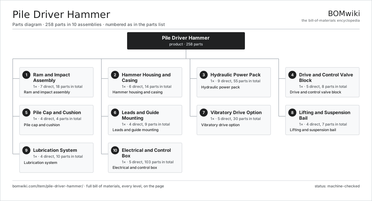
| # | Part | Qty | What it does |
|---|---|---|---|
| 1 | Ram and Impact Assembly 7 parts | 1× | Ram and impact assembly |
| 2 | Hammer Housing and Casing 6 parts | 1× | Hammer housing and casing |
| 3 | Hydraulic Power Pack 9 parts | 1× | Hydraulic power pack |
| 4 | Drive and Control Valve Block 5 parts | 1× | Drive and control valve block |
| 5 | Pile Cap and Cushion 4 parts | 1× | Pile cap and cushion |
| 6 | Leads and Guide Mounting 4 parts | 1× | Leads and guide mounting |
| 7 | Vibratory Drive Option 5 parts | 1× | Vibratory drive option |
| 8 | Lifting and Suspension Bail 4 parts | 1× | Lifting and suspension bail |
| 9 | Lubrication System 4 parts | 1× | Lubrication system |
| 10 | Electrical and Control Box 5 parts | 1× | Electrical and control box |
3D model
No 3D model yet. Have a CAD file of this? Add a 3D model — STL renders right on this page; STEP, FreeCAD, and OpenSCAD sources are welcome too (openly licensed, like all 3D models on BOMwiki).
Build & assembly graph
expand / collapse · shared sub-assemblies converge · links to related products · est. labourTap an assembly to expand/collapse · tap a part to open it · use “Open page” for any node · drag to pan, scroll to zoom.
Bill of materials for Pile Driver Hammer
10 top-level lines · 103 rows shown · 258 parts total · indented to 3 levels| # | Item / sub-assembly | Part no. | Qty/assy | Ext. qty | Parts | Type |
|---|---|---|---|---|---|---|
| 1 | Ram and Impact Assembly 7 parts | pile-driver-hammer-ram | 1× | 1 | 18 | assembly |
| 1.1 | Ram Weight | pile-driver-hammer-ram-weight | 1× | 1 | · | part |
| 1.2 | Accelerating Cylinder 5 parts | pile-driver-hammer-accel-cylinder | 1× | 1 | 8 | assembly |
| 1.2.1 | Cylinder Tube | pile-driver-hammer-cylinder-tube | 1× | 1 | · | part |
| 1.2.2 | Cylinder Piston | pile-driver-hammer-cylinder-piston | 1× | 1 | · | part |
| 1.2.3 | Piston Rod | pile-driver-hammer-piston-rod | 1× | 1 | · | part |
| 1.2.4 | O-Ring Set | oring-set | 3× | 3 | · | part |
| 1.2.5 | Oil Seal | oil-seal | 2× | 2 | · | part |
| 1.3 | Anvil / Striker | pile-driver-hammer-anvil | 1× | 1 | · | part |
| 1.4 | Impact Block | pile-driver-hammer-impact-block | 1× | 1 | · | part |
| 1.5 | Ram Guide Shoe | pile-driver-hammer-ram-guide-shoe | 4× | 4 | · | part |
| 1.6 | Piston Rod | pile-driver-hammer-piston-rod | 1× | 1 | · | part |
| 1.7 | O-Ring Set | oring-set | 2× | 2 | · | part |
| 2 | Hammer Housing and Casing 6 parts | pile-driver-hammer-housing | 1× | 1 | 14 | assembly |
| 2.1 | Cylindrical Housing | pile-driver-hammer-cylindrical-housing | 1× | 1 | · | part |
| 2.2 | Wear Plate | pile-driver-hammer-wear-plate | 6× | 6 | · | part |
| 2.3 | Slide Guide | pile-driver-hammer-slide-guide | 4× | 4 | · | part |
| 2.4 | Top Cap | pile-driver-hammer-top-cap | 1× | 1 | · | part |
| 2.5 | Bottom Flange | pile-driver-hammer-bottom-flange | 1× | 1 | · | part |
| 2.6 | Fastener Set | fastener-set | 1× | 1 | · | part |
| 3 | Hydraulic Power Pack 9 parts | pile-driver-hammer-power-pack | 1× | 1 | 55 | assembly |
| 3.1 | Diesel Engine 5 parts | pile-driver-hammer-diesel-engine | 1× | 1 | 10 | assembly |
| 3.1.1 | Engine Block | pile-driver-hammer-engine-block | 1× | 1 | · | part |
| 3.1.2 | Fuel System 3 parts + deeper › | pile-driver-hammer-fuel-system | 1× | 1 | 6 | assembly |
| 3.1.3 | Engine Radiator | pile-driver-hammer-engine-radiator | 1× | 1 | · | part |
| 3.1.4 | Exhaust and Muffler | pile-driver-hammer-exhaust | 1× | 1 | · | part |
| 3.1.5 | Starter Motor | pile-driver-hammer-starter | 1× | 1 | · | part |
| 3.2 | Electric Motor 4 parts | pile-driver-hammer-electric-motor | 1× | 1 | 25 | assembly |
| 3.2.1 | Stator Assembly 3 parts + deeper › | stator-assembly | 1× | 1 | 3 | assembly |
| 3.2.2 | Rotor Assembly 4 parts + deeper › | rotor-assembly | 1× | 1 | 19 | assembly |
| 3.2.3 | Motor Housing | motor-housing | 1× | 1 | · | part |
| 3.2.4 | Ball Bearing | ball-bearing | 2× | 2 | · | part |
| 3.3 | Hydraulic Pump 4 parts | pile-driver-hammer-hyd-pump | 1× | 1 | 5 | assembly |
| 3.3.1 | Pump Housing | pile-driver-hammer-pump-housing | 1× | 1 | · | part |
| 3.3.2 | Rotating Group | pile-driver-hammer-pump-rotating-group | 1× | 1 | · | part |
| 3.3.3 | Oil Seal | oil-seal | 1× | 1 | · | part |
| 3.3.4 | Ball Bearing | ball-bearing | 2× | 2 | · | part |
| 3.4 | Oil Reservoir | pile-driver-hammer-reservoir | 1× | 1 | · | part |
| 3.5 | Oil Cooler | pile-driver-hammer-oil-cooler | 1× | 1 | · | part |
| 3.6 | Hydraulic Filter | pile-driver-hammer-hyd-filter | 2× | 2 | · | part |
| 3.7 | Accumulator | pile-driver-hammer-accumulator | 1× | 1 | · | part |
| 3.8 | High-Pressure Hose Set 3 parts | pile-driver-hammer-hose-set | 1× | 1 | 8 | assembly |
| 3.8.1 | High-Pressure Hose | pile-driver-hammer-hp-hose | 2× | 2 | · | part |
| 3.8.2 | Return Hose | pile-driver-hammer-return-hose | 2× | 2 | · | part |
| 3.8.3 | Quick Coupler | pile-driver-hammer-quick-coupler | 4× | 4 | · | part |
| 3.9 | Pressure Sensor | pressure-sensor | 2× | 2 | · | part |
| 4 | Drive and Control Valve Block 5 parts | pile-driver-hammer-valve-block | 1× | 1 | 8 | assembly |
| 4.1 | Valve Manifold | pile-driver-hammer-manifold | 1× | 1 | · | part |
| 4.2 | Directional Valve | pile-driver-hammer-directional-valve | 1× | 1 | · | part |
| 4.3 | Trip Mechanism 3 parts | pile-driver-hammer-trip-mechanism | 1× | 1 | 3 | assembly |
| 4.3.1 | Trip Lever | pile-driver-hammer-trip-lever | 1× | 1 | · | part |
| 4.3.2 | Trip Cam | pile-driver-hammer-trip-cam | 1× | 1 | · | part |
| 4.3.3 | Coil Spring | coil-spring | 1× | 1 | · | part |
| 4.4 | Relief Valve | pile-driver-hammer-relief-valve | 1× | 1 | · | part |
| 4.5 | O-Ring Set | oring-set | 2× | 2 | · | part |
| 5 | Pile Cap and Cushion 4 parts | pile-driver-hammer-drive-cap | 1× | 1 | 4 | assembly |
| 5.1 | Drive Helmet | pile-driver-hammer-helmet | 1× | 1 | · | part |
| 5.2 | Hammer Cushion | pile-driver-hammer-hammer-cushion | 1× | 1 | · | part |
| 5.3 | Pile Cushion / Dolly | pile-driver-hammer-pile-cushion | 1× | 1 | · | part |
| 5.4 | Drive Insert | pile-driver-hammer-drive-insert | 1× | 1 | · | part |
| 6 | Leads and Guide Mounting 4 parts | pile-driver-hammer-leads | 1× | 1 | 9 | assembly |
| 6.1 | Leader Rail | pile-driver-hammer-leader-rail | 2× | 2 | · | part |
| 6.2 | Guide Jaw | pile-driver-hammer-guide-jaw | 4× | 4 | · | part |
| 6.3 | Lead Clamp | pile-driver-hammer-clamp | 2× | 2 | · | part |
| 6.4 | Spotter Brace | pile-driver-hammer-spotter | 1× | 1 | · | part |
| 7 | Vibratory Drive Option 5 parts | pile-driver-hammer-vibratory | 1× | 1 | 30 | assembly |
| 7.1 | Eccentric Weight | pile-driver-hammer-eccentric-weight | 4× | 4 | · | part |
| 7.2 | Vibrator Gearbox 4 parts | pile-driver-hammer-vibrator-gearbox | 1× | 1 | 13 | assembly |
| 7.2.1 | Helical Gear Pair | gear-pair | 2× | 2 | · | part |
| 7.2.2 | Gearbox Housing | gearbox-housing | 1× | 1 | · | part |
| 7.2.3 | Ball Bearing | ball-bearing | 8× | 8 | · | part |
| 7.2.4 | Oil Seal | oil-seal | 2× | 2 | · | part |
| 7.3 | Suppressor Housing | pile-driver-hammer-suppressor | 1× | 1 | · | part |
| 7.4 | Coil Spring | coil-spring | 8× | 8 | · | part |
| 7.5 | Clamp Jaw 3 parts | pile-driver-hammer-clamp-jaw | 1× | 1 | 4 | assembly |
| 7.5.1 | Clamp Cylinder | pile-driver-hammer-clamp-cylinder | 1× | 1 | · | part |
| 7.5.2 | Clamp Tooth | pile-driver-hammer-clamp-tooth | 2× | 2 | · | part |
| 7.5.3 | O-Ring Set | oring-set | 1× | 1 | · | part |
| 8 | Lifting and Suspension Bail 4 parts | pile-driver-hammer-bail | 1× | 1 | 7 | assembly |
| 8.1 | Bail Frame | pile-driver-hammer-bail-frame | 1× | 1 | · | part |
| 8.2 | Bail Sheave | pile-driver-hammer-sheave | 2× | 2 | · | part |
| 8.3 | Shackle | pile-driver-hammer-shackle | 2× | 2 | · | part |
| 8.4 | Ball Bearing | ball-bearing | 2× | 2 | · | part |
| 9 | Lubrication System 4 parts | pile-driver-hammer-lubrication | 1× | 1 | 10 | assembly |
| 9.1 | Grease Pump | pile-driver-hammer-grease-pump | 1× | 1 | · | part |
| 9.2 | Grease Reservoir | pile-driver-hammer-grease-reservoir | 1× | 1 | · | part |
| 9.3 | Grease Line | pile-driver-hammer-grease-line | 4× | 4 | · | part |
| 9.4 | Grease Nozzle | pile-driver-hammer-grease-nozzle | 4× | 4 | · | part |
| 10 | Electrical and Control Box 5 parts | pile-driver-hammer-control-box | 1× | 1 | 103 | assembly |
| 10.1 | Control Panel 6 parts | pile-driver-hammer-control-panel | 1× | 1 | 90 | assembly |
| 10.1.1 | Bare PCB | pcb-bare | 1× | 1 | · | part |
| 10.1.2 | Microcontroller | mcu | 1× | 1 | · | part |
| 10.1.3 | Relay | relay | 6× | 6 | · | part |
| 10.1.4 | SMD Passive (R/C/L) | smd-passives | 80× | 80 | · | part |
| 10.1.5 | LCD Panel | lcd-panel | 1× | 1 | · | part |
| 10.1.6 | Power Supply | power-supply | 1× | 1 | · | part |
| 10.2 | Operator Remote | pile-driver-hammer-remote | 1× | 1 | · | part |
| 10.3 | Driving Instrumentation 3 parts | pile-driver-hammer-instrumentation | 1× | 1 | 3 | assembly |
| 10.3.1 | Blow Counter | pile-driver-hammer-blow-counter | 1× | 1 | · | part |
| 10.3.2 | Energy Sensor | pile-driver-hammer-energy-sensor | 1× | 1 | · | part |
| 10.3.3 | Pressure Sensor | pressure-sensor | 1× | 1 | · | part |
| 10.4 | Wire Bundle | wire-bundle | 1× | 1 | · | part |
| 10.5 | Connector | connector | 8× | 8 | · | part |
Used in 1 assembly
Related products
same domain, ranked by shared parts Bridge Girder Launching Gantry
1,542 parts · shares 21 with this page
Bridge Girder Launching Gantry
1,542 parts · shares 21 with this page
 Guardrail Installation Rig
320 parts · shares 21 with this page
Guardrail Installation Rig
320 parts · shares 21 with this page
 Rebar Cage Welding Machine
1,702 parts · shares 21 with this page
Rebar Cage Welding Machine
1,702 parts · shares 21 with this page
 Tandem Vibratory Roller
369 parts · shares 21 with this page
Tandem Vibratory Roller
369 parts · shares 21 with this page
 Tracked Asphalt Paver
1,299 parts · shares 21 with this page
Tracked Asphalt Paver
1,299 parts · shares 21 with this page
Sourcing: possible vendors
Prices, MOQ, and lead times are algorithmic estimates, not quotes, and not claims about these companies. Company mappings are curated by keyword; est. price band $15k–$2M. How estimates work| Vendor | HQ | Specialty | MOQ | Lead time |
|---|---|---|---|---|
| caterpillar.com ↗ | Irving, US | Construction & mining equipment | made to order | 16–28 wks |
|
🇯🇵Komatsu
komatsu.com ↗
|
Tokyo, JP | Construction & mining equipment | made to order | 16–28 wks |
|
🇸🇪Volvo CE
volvoce.com ↗
|
Gothenburg, SE | Construction equipment | made to order | 16–28 wks |
|
🇨🇭Liebherr
liebherr.com ↗
|
Bulle, CH | Cranes & heavy equipment | made to order | 16–28 wks |
|
🇨🇳XCMG
xcmg.com ↗
|
Xuzhou, CN | Construction machinery | made to order | 16–28 wks |
1,106-word article