Vibroflotation Probe
ProductOverview
A vibroflotation probe, or depth vibrator, improves soft and loose ground from the inside. It is a long steel tube with a spinning off-center weight that shakes the tube sideways. Lowered into the soil, that horizontal vibration rearranges loose sand grains into a denser packing, and where the soil is too soft to compact on its own, the same probe builds a column of imported gravel that stiffens and drains the ground. The technique is standard under tanks, embankments, wind turbine bases and buildings on reclaimed or alluvial soils.
Two jobs share one tool. Vibro-compaction densifies clean sands directly. Vibro stone columns treat clays and silts by replacing a share of the soft soil with compacted gravel. The Vibrator Body makes the vibration, the Eccentric Drive generates it, the Nose Cone sinks the probe, and the Supply System feeds water, air and stone.
How it densifies soil
Inside the Vibrator Body tube, the Drive Motor spins the Eccentric Weight on the Drive Shaft. An off-center mass turning at 30 to 60 Hz throws the whole tube in a horizontal circle, with a centrifugal force of 150 to 300 kN and an amplitude of several millimetres at the tip. That sideways motion is what compacts the soil: vertical vibration would just drive the probe down without densifying the ground around it.
In clean sand, the vibration breaks the loose grain structure and lets the grains settle into a tighter arrangement. The ground around the probe densifies, sand is added at the surface to make up the volume lost, and the result is a compacted zone a metre or more in radius around each probe point. The Stabilizing Fin blades along the body grip the soil so the probe vibrates against it rather than spinning in place.
Sinking the probe
The Nose Cone lets the probe sink itself. The Water Jet ports at the Hardened Tip fluidize the soil ahead of the probe so it penetrates under its own weight, and the upflow flushes fine material out of the hole. The Air Jet ports lift the annulus and, in dry construction, help feed stone down. Water and air reach the tip through the Jet Passage channels fed from the supply lines. The tip is hardened because sinking through sand and gravel is abrasive.
To reach depth, Extension Tube follower tubes bolt above the vibrator. Stacked Tube Section pieces set the treatment depth, joined at Tube Flange flanges, and the Supply Line routes water, air and stone down inside them. With followers, modern probes reach 30 m or more.
Keeping vibration where it belongs
The vibrator must shake hard at the tip while the crane and the follower tubes stay relatively still. The Isolator Coupling does that. Its Elastic Element rubber isolator and Coil Spring set decouple the vibrating body from the static tubes, so the energy goes into the soil instead of back up into the rig. Without good isolation the follower tubes and the crane would fatigue quickly and the probe would lose amplitude at the tip.
Building stone columns
In soft clays and silts that will not compact on their own, the probe builds a Supply System fed gravel column. The Stone Hopper meters aggregate and the Air Compressor air drives it down the Bottom-Feed Tube to the tip, where the vibrating probe rams it sideways into the soil. The column is built up in lifts: the probe is raised a short distance, stone is fed in, and the probe pushes back down to compact it. The finished column carries load, stiffens the soil mass, and acts as a vertical drain that speeds consolidation. Top-feed construction drops stone down the open hole around the probe; bottom-feed delivers it to the tip through the tube, which works below the water table without a stable hole.
Power, water and air
The Supply System runs the probe. The Water Pump supplies the high flow the jets need for wet penetration, the Air Compressor feeds the air jets and bottom-feed line, and a Pressure Sensor watches each supply. The Drive Motor is hydraulic or electric depending on the rig; either way the eccentric runs on heavy Main Bearing and Ball Bearing sets sized for the constant radial throw.
Control and records
The quality of the work is judged from the probe data, not by digging it up, so the Process Control system records it. The Depth Sensor tracks how deep the probe is, the Current Sensor reads drive current, which rises as the soil densifies and resists the vibration, and the Process Controller correlates the two to confirm the target density at each depth. The Process Recorder saves depth, current and stone volume for every column so the engineer has a record of the whole treated area.
Variants and use
Probe size follows the soil and the depth: shorter high-frequency vibrators for shallow compaction of clean sand, longer high-force vibrators with followers for deep stone columns under heavy structures. Vibroflotation is widely used on reclaimed land, river and coastal deposits, and loose hydraulic fills, where it both stiffens the ground against settlement and reduces the risk of liquefaction in seismic areas.
Vibroflotation Probe parts and their functions
7 top-level parts · 114 parts in total · full bill of materials below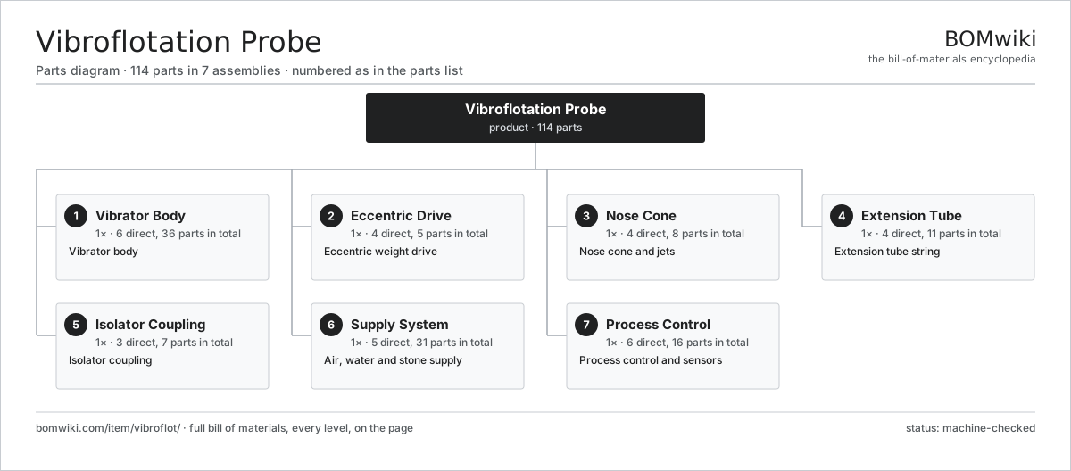
| # | Part | Qty | What it does |
|---|---|---|---|
| 1 | Vibrator Body 6 parts | 1× | Vibrator body |
| 2 | Eccentric Drive 4 parts | 1× | Eccentric weight drive |
| 3 | Nose Cone 4 parts | 1× | Nose cone and jets |
| 4 | Extension Tube 4 parts | 1× | Extension tube string |
| 5 | Isolator Coupling 3 parts | 1× | Isolator coupling |
| 6 | Supply System 5 parts | 1× | Air, water and stone supply |
| 7 | Process Control 6 parts | 1× | Process control and sensors |
3D model
No 3D model yet. Have a CAD file of this? Add a 3D model — STL renders right on this page; STEP, FreeCAD, and OpenSCAD sources are welcome too (openly licensed, like all 3D models on BOMwiki).
Build & assembly graph
expand / collapse · shared sub-assemblies converge · links to related products · est. labourTap an assembly to expand/collapse · tap a part to open it · use “Open page” for any node · drag to pan, scroll to zoom.
Bill of materials for Vibroflotation Probe
7 top-level lines · 50 rows shown · 114 parts total · indented to 3 levels| # | Item / sub-assembly | Part no. | Qty/assy | Ext. qty | Parts | Type |
|---|---|---|---|---|---|---|
| 1 | Vibrator Body 6 parts | vibroflot-vibrator-body | 1× | 1 | 36 | assembly |
| 1.1 | Body Tube | vibroflot-body-tube | 1× | 1 | · | part |
| 1.2 | Drive Motor 4 parts | vibroflot-drive-motor | 1× | 1 | 25 | assembly |
| 1.2.1 | Stator Assembly 3 parts + deeper › | stator-assembly | 1× | 1 | 3 | assembly |
| 1.2.2 | Rotor Assembly 4 parts + deeper › | rotor-assembly | 1× | 1 | 19 | assembly |
| 1.2.3 | Ball Bearing | ball-bearing | 2× | 2 | · | part |
| 1.2.4 | Oil Seal | oil-seal | 1× | 1 | · | part |
| 1.3 | Main Bearing | vibroflot-main-bearing | 2× | 2 | · | part |
| 1.4 | Stabilizing Fin | vibroflot-fin | 4× | 4 | · | part |
| 1.5 | Oil Seal | oil-seal | 3× | 3 | · | part |
| 1.6 | O-Ring Set | oring-set | 1× | 1 | · | part |
| 2 | Eccentric Drive 4 parts | vibroflot-eccentric-drive | 1× | 1 | 5 | assembly |
| 2.1 | Eccentric Weight | vibroflot-eccentric-weight | 1× | 1 | · | part |
| 2.2 | Drive Shaft | vibroflot-drive-shaft | 1× | 1 | · | part |
| 2.3 | Ball Bearing | ball-bearing | 2× | 2 | · | part |
| 2.4 | Shaft Coupling | vibroflot-shaft-coupling | 1× | 1 | · | part |
| 3 | Nose Cone 4 parts | vibroflot-nose-cone | 1× | 1 | 8 | assembly |
| 3.1 | Hardened Tip | vibroflot-tip | 1× | 1 | · | part |
| 3.2 | Water Jet | vibroflot-water-jet | 4× | 4 | · | part |
| 3.3 | Air Jet | vibroflot-air-jet | 2× | 2 | · | part |
| 3.4 | Jet Passage | vibroflot-jet-passage | 1× | 1 | · | part |
| 4 | Extension Tube 4 parts | vibroflot-extension-tube | 1× | 1 | 11 | assembly |
| 4.1 | Tube Section | vibroflot-tube-section | 4× | 4 | · | part |
| 4.2 | Tube Flange | vibroflot-tube-flange | 5× | 5 | · | part |
| 4.3 | Supply Line | vibroflot-supply-line | 1× | 1 | · | part |
| 4.4 | Fastener Set | fastener-set | 1× | 1 | · | part |
| 5 | Isolator Coupling 3 parts | vibroflot-coupling | 1× | 1 | 7 | assembly |
| 5.1 | Elastic Element | vibroflot-elastic-element | 1× | 1 | · | part |
| 5.2 | Coupling Plate | vibroflot-coupling-plate | 2× | 2 | · | part |
| 5.3 | Coil Spring | coil-spring | 4× | 4 | · | part |
| 6 | Supply System 5 parts | vibroflot-supply-system | 1× | 1 | 31 | assembly |
| 6.1 | Water Pump 3 parts | vibroflot-water-pump | 1× | 1 | 26 | assembly |
| 6.1.1 | Servo Motor 4 parts + deeper › | servo-motor | 1× | 1 | 24 | assembly |
| 6.1.2 | Pump Impeller | vibroflot-pump-impeller | 1× | 1 | · | part |
| 6.1.3 | Oil Seal | oil-seal | 1× | 1 | · | part |
| 6.2 | Air Compressor | vibroflot-compressor | 1× | 1 | · | part |
| 6.3 | Stone Hopper | vibroflot-stone-hopper | 1× | 1 | · | part |
| 6.4 | Bottom-Feed Tube | vibroflot-bottom-feed-tube | 1× | 1 | · | part |
| 6.5 | Pressure Sensor | pressure-sensor | 2× | 2 | · | part |
| 7 | Process Control 6 parts | vibroflot-control | 1× | 1 | 16 | assembly |
| 7.1 | Process Controller 4 parts | vibroflot-controller | 1× | 1 | 6 | assembly |
| 7.1.1 | Bare PCB | pcb-bare | 1× | 1 | · | part |
| 7.1.2 | Microcontroller | mcu | 1× | 1 | · | part |
| 7.1.3 | SMD Passive (R/C/L) | smd-passives | 1× | 1 | · | part |
| 7.1.4 | Relay | relay | 3× | 3 | · | part |
| 7.2 | Depth Sensor | vibroflot-depth-sensor | 1× | 1 | · | part |
| 7.3 | Current Sensor | vibroflot-amp-sensor | 1× | 1 | · | part |
| 7.4 | Process Recorder | vibroflot-recorder | 1× | 1 | · | part |
| 7.5 | Wire Bundle | wire-bundle | 1× | 1 | · | part |
| 7.6 | Connector | connector | 6× | 6 | · | part |
Related products
same domain, ranked by shared parts Bridge Girder Launching Gantry
1,542 parts · shares 19 with this page
Bridge Girder Launching Gantry
1,542 parts · shares 19 with this page
 Guardrail Installation Rig
320 parts · shares 19 with this page
Guardrail Installation Rig
320 parts · shares 19 with this page
 Tandem Vibratory Roller
369 parts · shares 19 with this page
Tandem Vibratory Roller
369 parts · shares 19 with this page
 Tracked Asphalt Paver
1,299 parts · shares 19 with this page
Tracked Asphalt Paver
1,299 parts · shares 19 with this page
 Asphalt Recycler
226 parts · shares 18 with this page
Asphalt Recycler
226 parts · shares 18 with this page
 Cold In-Place Recycling Train
657 parts · shares 18 with this page
Cold In-Place Recycling Train
657 parts · shares 18 with this page
Sourcing: possible vendors
Prices, MOQ, and lead times are algorithmic estimates, not quotes, and not claims about these companies. Company mappings are curated by keyword; est. price band $15k–$2M. How estimates work| Vendor | HQ | Specialty | MOQ | Lead time |
|---|---|---|---|---|
| caterpillar.com ↗ | Irving, US | Construction & mining equipment | made to order | 16–28 wks |
|
🇯🇵Komatsu
komatsu.com ↗
|
Tokyo, JP | Construction & mining equipment | made to order | 16–28 wks |
|
🇸🇪Volvo CE
volvoce.com ↗
|
Gothenburg, SE | Construction equipment | made to order | 16–28 wks |
|
🇨🇭Liebherr
liebherr.com ↗
|
Bulle, CH | Cranes & heavy equipment | made to order | 16–28 wks |
|
🇨🇳XCMG
xcmg.com ↗
|
Xuzhou, CN | Construction machinery | made to order | 16–28 wks |
893-word article