Tunnel Boring Machine
ProductOverview
A tunnel boring machine excavates a circular tunnel in a single continuous operation, replacing drill-and-blast methods with a rotating full-face cutting wheel. This earth-pressure-balance variant is built for soft ground and mixed-face conditions: it holds the excavation chamber under controlled pressure so the tunnel face cannot collapse or flood while the Cutterhead grinds forward. The whole machine is a self-contained underground factory, it cuts ground, removes spoil through the Muck Removal System system, and builds a watertight concrete lining behind itself as it advances.
The working end is the shielded boring unit; a long Trailing Gantry towed behind carries the transformers, pumps, and material supply that the front cannot house.
How it works
The Cutterhead is a welded steel wheel studded with disc cutters. A ring of electric drive motors turns it through reduction gearboxes and a single large Main Bearing, the most heavily loaded component in the machine. The disc cutters roll under enormous load against the rock, propagating cracks that spall chips off the face; softer ground is simply scraped and mixed into a paste.
Forward force comes from the Thrust & Gripper System. Hydraulic propulsion cylinders push off the last completed lining ring, driving the whole shield ahead by one segment width per cycle. Excavated material enters the pressurised chamber and is drawn out by a screw conveyor that meters spoil while maintaining face pressure, then dropped onto a belt that runs the length of the machine.
Once the shield has advanced a full stroke, the Segment Erector rotates precast concrete segments into place to build the next ring; the thrust cylinders then push off this fresh ring. Every function, thrust, steering, erector, screw, is driven by the Hydraulic Power Pack pack. The Guidance & Control System system references a tunnel laser against a target on the shield, continuously correcting line and grade by extending the thrust cylinders unevenly, with the operator overseeing it from the Operator Cab.
Tunnel Boring Machine parts and their functions
15 top-level parts · 46,929 parts in total · full bill of materials below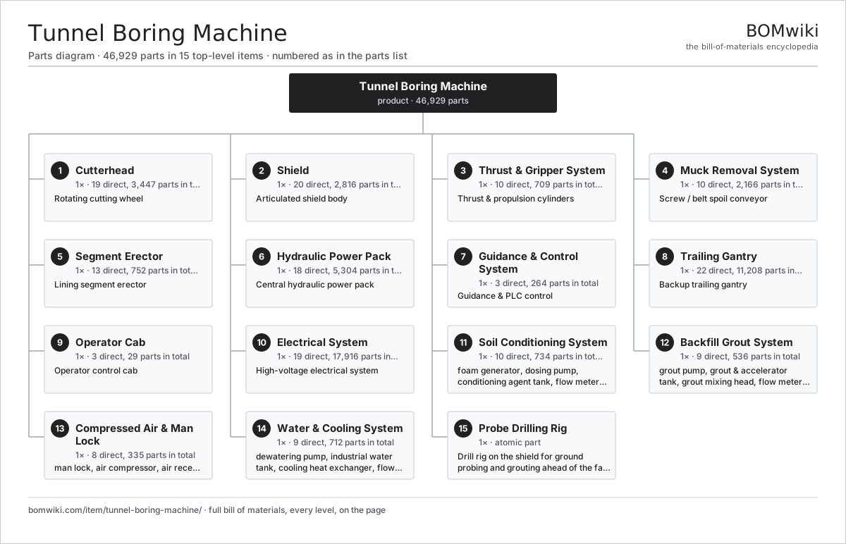
| # | Part | Qty | What it does |
|---|---|---|---|
| 1 | Cutterhead 19 parts | 1× | Rotating cutting wheel |
| 2 | Shield 20 parts | 1× | Articulated shield body |
| 3 | Thrust & Gripper System 10 parts | 1× | Thrust & propulsion cylinders |
| 4 | Muck Removal System 10 parts | 1× | Screw / belt spoil conveyor |
| 5 | Segment Erector 13 parts | 1× | Lining segment erector |
| 6 | Hydraulic Power Pack 18 parts | 1× | Central hydraulic power pack |
| 7 | Guidance & Control System 3 parts | 1× | Guidance & PLC control |
| 8 | Trailing Gantry 22 parts | 1× | Backup trailing gantry |
| 9 | Operator Cab 3 parts | 1× | Operator control cab |
| 10 | Electrical System 19 parts | 1× | High-voltage electrical system |
| 11 | Soil Conditioning System 10 parts | 1× | Foam, polymer and bentonite plant that conditions the excavated soil so the EPB chamber holds pressure and the screw conveyor extracts it. |
| 12 | Backfill Grout System 9 parts | 1× | Tanks, pumps, lines and injection ports that fill the annular gap behind the lining as the machine advances. |
| 13 | Compressed Air & Man Lock 8 parts | 1× | Compressors, receivers, regulation and the man lock for pressurised access to the cutterhead. |
| 14 | Water & Cooling System 9 parts | 1× | Industrial water supply, cooling circuits for drives and hydraulics, and dewatering. |
| 15 | Probe Drilling Rig | 1× | Drill rig on the shield for ground probing and grouting ahead of the face. |
Diagrams & photos

3D model
No 3D model yet. Have a CAD file of this? Add a 3D model. STL renders right on this page; STEP, FreeCAD, and OpenSCAD sources are welcome too (openly licensed, like all 3D models on BOMwiki).
Build & assembly graph
expand / collapse · shared sub-assemblies converge · links to related products · est. labourTap an assembly to expand/collapse · tap a part to open it · use “Open page” for any node · drag to pan, scroll to zoom.
Bill of materials for Tunnel Boring Machine
15 top-level lines · 285 rows shown · 46,929 parts total · indented to 3 levels| # | Item / sub-assembly | Part no. | Qty/assy | Ext. qty | Parts | Type |
|---|---|---|---|---|---|---|
| 1 | Cutterhead 19 parts | tbm-cutterhead | 1× | 1 | 3,447 | assembly |
| 1.1 | Cutting Wheel Structure | tbm-cutterhead-structure | 1× | 1 | · | part |
| 1.2 | Disc Cutter 4 parts | tbm-disc-cutter | 38× | 38 | 6 | assembly |
| 1.2.1 | Cutter Ring | tbm-cutter-ring | 1× | 38 | · | part |
| 1.2.2 | Cutter Hub & Shaft | tbm-cutter-hub | 1× | 38 | · | part |
| 1.2.3 | Ball Bearing | ball-bearing | 2× | 76 | · | part |
| 1.2.4 | Oil Seal | oil-seal | 2× | 76 | · | part |
| 1.3 | Cutterhead Drive Motor 4 parts | tbm-drive-motor | 8× | 8 | 25 | assembly |
| 1.3.1 | Stator Assembly 3 parts + deeper › | stator-assembly | 1× | 8 | 3 | assembly |
| 1.3.2 | Rotor Assembly 4 parts + deeper › | rotor-assembly | 1× | 8 | 19 | assembly |
| 1.3.3 | Motor Housing | motor-housing | 1× | 8 | · | part |
| 1.3.4 | Ball Bearing | ball-bearing | 2× | 16 | · | part |
| 1.4 | Main Bearing 3 parts | tbm-main-bearing | 1× | 1 | 123 | assembly |
| 1.4.1 | Bearing Race | tbm-bearing-race | 2× | 2 | · | part |
| 1.4.2 | Roller Element | tbm-bearing-roller | 120× | 120 | · | part |
| 1.4.3 | Slew Ring Gear | tbm-bearing-gear | 1× | 1 | · | part |
| 1.5 | Gearbox Housing | gearbox-housing | 8× | 8 | · | part |
| 1.6 | Helical Gear Pair | gear-pair | 16× | 16 | · | part |
| 1.7 | Main Bearing Seal Assembly 2 parts | tbm-cutterhead-seal | 1× | 1 | 8 | assembly |
| 1.7.1 | Oil Seal | oil-seal | 4× | 4 | · | part |
| 1.7.2 | O-Ring Set | oring-set | 4× | 4 | · | part |
| 1.8 | Scraper Tool | tbm-scraper | 160× | 160 | · | part |
| 1.9 | Bucket Lip | tbm-bucket-lip | 40× | 40 | · | part |
| 1.10 | Wear Plate | tbm-wear-plate | 220× | 220 | · | part |
| 1.11 | Cutter Housing Bolt | tbm-cutter-housing-bolt | 608× | 608 | · | part |
| 1.12 | Ring Gear & Bearing Bolt | tbm-ring-gear-bolt | 320× | 320 | · | part |
| 1.13 | Foam Injection Nozzle | tbm-foam-nozzle | 12× | 12 | · | part |
| 1.14 | Rotary Union | tbm-rotary-joint | 1× | 1 | · | part |
| 1.15 | Copy Cutter | tbm-copy-cutter | 2× | 2 | · | part |
| 1.16 | Grease Line & Fitting | tbm-cutter-lubrication | 60× | 60 | · | part |
| 1.17 | Heavy Structural Bolt | tbm-heavy-bolt | 240× | 240 | · | part |
| 1.18 | Hex Nut | tbm-hex-nut | 600× | 600 | · | part |
| 1.19 | Washer | tbm-washer | 600× | 600 | · | part |
| 2 | Shield 20 parts | tbm-shield | 1× | 1 | 2,816 | assembly |
| 2.1 | Front Shield & Bulkhead | tbm-front-shield | 1× | 1 | · | part |
| 2.2 | Middle Shield | tbm-middle-shield | 1× | 1 | · | part |
| 2.3 | Tail Shield | tbm-tail-shield | 1× | 1 | · | part |
| 2.4 | Articulation Cylinder 4 parts | tbm-articulation-cylinder | 8× | 8 | 6 | assembly |
| 2.4.1 | Cylinder Barrel | tbm-cyl-barrel | 1× | 8 | · | part |
| 2.4.2 | Cylinder Rod | tbm-cyl-rod | 1× | 8 | · | part |
| 2.4.3 | O-Ring Set | oring-set | 2× | 16 | · | part |
| 2.4.4 | Oil Seal | oil-seal | 2× | 16 | · | part |
| 2.5 | Tail Brush Seal | tbm-tail-seal | 1× | 1 | · | part |
| 2.6 | Tail Seal Brush | tbm-brush | 640× | 640 | · | part |
| 2.7 | Tail Seal Grease Port | tbm-grease-injection | 24× | 24 | · | part |
| 2.8 | Grout Injection Line | tbm-grout-line | 12× | 12 | · | part |
| 2.9 | Shield Port & Cover | tbm-shield-port | 20× | 20 | · | part |
| 2.10 | Bulkhead Penetration | tbm-bulkhead-fitting | 90× | 90 | · | part |
| 2.11 | Chamber Agitator | tbm-agitator | 4× | 4 | · | part |
| 2.12 | Earth Pressure Sensor | tbm-earth-pressure-sensor | 8× | 8 | · | part |
| 2.13 | Walkway & Platform Plate | tbm-walkway | 40× | 40 | · | part |
| 2.14 | Handrail Section | tbm-handrail | 30× | 30 | · | part |
| 2.15 | Cylinder Seal Kit | tbm-cylinder-seal-kit | 8× | 8 | · | part |
| 2.16 | Cylinder Stroke Sensor | tbm-stroke-sensor | 8× | 8 | · | part |
| 2.17 | Heavy Structural Bolt | tbm-heavy-bolt | 180× | 180 | · | part |
| 2.18 | Hex Bolt | tbm-hex-bolt | 700× | 700 | · | part |
| 2.19 | Hex Nut | tbm-hex-nut | 500× | 500 | · | part |
| 2.20 | Washer | tbm-washer | 500× | 500 | · | part |
| 3 | Thrust & Gripper System 10 parts | tbm-thrust-system | 1× | 1 | 709 | assembly |
| 3.1 | Thrust Cylinder 4 parts | tbm-thrust-cylinder | 19× | 19 | 8 | assembly |
| 3.1.1 | Cylinder Barrel | tbm-cyl-barrel | 1× | 19 | · | part |
| 3.1.2 | Cylinder Rod | tbm-cyl-rod | 1× | 19 | · | part |
| 3.1.3 | O-Ring Set | oring-set | 3× | 57 | · | part |
| 3.1.4 | Oil Seal | oil-seal | 3× | 57 | · | part |
| 3.2 | Thrust Spreader Shoe | tbm-thrust-shoe | 19× | 19 | · | part |
| 3.3 | Gripper Pad | tbm-gripper | 2× | 2 | · | part |
| 3.4 | Gripper Cylinder 4 parts | tbm-gripper-cylinder | 2× | 2 | 6 | assembly |
| 3.4.1 | Cylinder Barrel | tbm-cyl-barrel | 1× | 2 | · | part |
| 3.4.2 | Cylinder Rod | tbm-cyl-rod | 1× | 2 | · | part |
| 3.4.3 | O-Ring Set | oring-set | 2× | 4 | · | part |
| 3.4.4 | Oil Seal | oil-seal | 2× | 4 | · | part |
| 3.5 | Cylinder Seal Kit | tbm-cylinder-seal-kit | 21× | 21 | · | part |
| 3.6 | Cylinder Stroke Sensor | tbm-stroke-sensor | 19× | 19 | · | part |
| 3.7 | Hydraulic Hose Assembly | tbm-hydraulic-hose | 60× | 60 | · | part |
| 3.8 | Hydraulic Fitting | tbm-hose-fitting | 120× | 120 | · | part |
| 3.9 | Heavy Structural Bolt | tbm-heavy-bolt | 152× | 152 | · | part |
| 3.10 | Hex Nut | tbm-hex-nut | 152× | 152 | · | part |
| 4 | Muck Removal System 10 parts | tbm-muck-removal | 1× | 1 | 2,166 | assembly |
| 4.1 | Screw Conveyor 5 parts | tbm-screw-conveyor | 1× | 1 | 9 | assembly |
| 4.1.1 | Screw Auger Flight | tbm-screw-flight | 1× | 1 | · | part |
| 4.1.2 | Screw Casing | tbm-screw-casing | 1× | 1 | · | part |
| 4.1.3 | Gearbox Housing | gearbox-housing | 1× | 1 | · | part |
| 4.1.4 | Ball Bearing | ball-bearing | 4× | 4 | · | part |
| 4.1.5 | Oil Seal | oil-seal | 2× | 2 | · | part |
| 4.2 | Belt Conveyor 3 parts | tbm-belt-conveyor | 1× | 1 | 42 | assembly |
| 4.2.1 | Conveyor Belt | tbm-conveyor-belt | 1× | 1 | · | part |
| 4.2.2 | Conveyor Idler Roller | tbm-conveyor-roller | 40× | 40 | · | part |
| 4.2.3 | Conveyor Frame | tbm-conveyor-frame | 1× | 1 | · | part |
| 4.3 | Conveyor Drive Motor 4 parts | tbm-conveyor-motor | 3× | 3 | 25 | assembly |
| 4.3.1 | Stator Assembly 3 parts + deeper › | stator-assembly | 1× | 3 | 3 | assembly |
| 4.3.2 | Rotor Assembly 4 parts + deeper › | rotor-assembly | 1× | 3 | 19 | assembly |
| 4.3.3 | Motor Housing | motor-housing | 1× | 3 | · | part |
| 4.3.4 | Ball Bearing | ball-bearing | 2× | 6 | · | part |
| 4.4 | Screw Discharge Gate | tbm-screw-gate | 2× | 2 | · | part |
| 4.5 | Belt Idler Roller | tbm-belt-idler | 180× | 180 | · | part |
| 4.6 | Conveyor Frame Section | tbm-belt-frame | 45× | 45 | · | part |
| 4.7 | Belt Cleaner & Skirt | tbm-belt-scraper | 12× | 12 | · | part |
| 4.8 | Belt Scale & Speed Sensor | tbm-belt-scale | 1× | 1 | · | part |
| 4.9 | Hex Bolt | tbm-hex-bolt | 900× | 900 | · | part |
| 4.10 | Hex Nut | tbm-hex-nut | 900× | 900 | · | part |
| 5 | Segment Erector 13 parts | tbm-segment-erector | 1× | 1 | 752 | assembly |
| 5.1 | Erector Arm | tbm-erector-arm | 1× | 1 | · | part |
| 5.2 | Erector Slew Ring 3 parts | tbm-erector-ring | 1× | 1 | 83 | assembly |
| 5.2.1 | Bearing Race | tbm-bearing-race | 2× | 2 | · | part |
| 5.2.2 | Roller Element | tbm-bearing-roller | 80× | 80 | · | part |
| 5.2.3 | Helical Gear Pair | gear-pair | 1× | 1 | · | part |
| 5.3 | Erector Rotation Motor 4 parts | tbm-erector-motor | 1× | 1 | 25 | assembly |
| 5.3.1 | Stator Assembly 3 parts + deeper › | stator-assembly | 1× | 1 | 3 | assembly |
| 5.3.2 | Rotor Assembly 4 parts + deeper › | rotor-assembly | 1× | 1 | 19 | assembly |
| 5.3.3 | Motor Housing | motor-housing | 1× | 1 | · | part |
| 5.3.4 | Ball Bearing | ball-bearing | 2× | 2 | · | part |
| 5.4 | Vacuum Grip Head | tbm-vacuum-grip | 1× | 1 | · | part |
| 5.5 | Erector Positioning Cylinder 4 parts | tbm-erector-cylinder | 4× | 4 | 6 | assembly |
| 5.5.1 | Cylinder Barrel | tbm-cyl-barrel | 1× | 4 | · | part |
| 5.5.2 | Cylinder Rod | tbm-cyl-rod | 1× | 4 | · | part |
| 5.5.3 | O-Ring Set | oring-set | 2× | 8 | · | part |
| 5.5.4 | Oil Seal | oil-seal | 2× | 8 | · | part |
| 5.6 | Segment Feeder | tbm-segment-feeder | 1× | 1 | · | part |
| 5.7 | Segment Crane | tbm-segment-crane | 1× | 1 | · | part |
| 5.8 | Segment Bolting Tool | tbm-erector-bolt-drill | 2× | 2 | · | part |
| 5.9 | Cylinder Seal Kit | tbm-cylinder-seal-kit | 4× | 4 | · | part |
| 5.10 | Hydraulic Hose Assembly | tbm-hydraulic-hose | 40× | 40 | · | part |
| 5.11 | Hydraulic Fitting | tbm-hose-fitting | 90× | 90 | · | part |
| 5.12 | Hex Bolt | tbm-hex-bolt | 240× | 240 | · | part |
| 5.13 | Hex Nut | tbm-hex-nut | 240× | 240 | · | part |
| 6 | Hydraulic Power Pack 18 parts | tbm-hydraulic-power | 1× | 1 | 5,304 | assembly |
| 6.1 | Axial Piston Pump 4 parts | tbm-hyd-pump | 4× | 4 | 7 | assembly |
| 6.1.1 | Pump Rotating Group | tbm-pump-rotating-group | 1× | 4 | · | part |
| 6.1.2 | Ball Bearing | ball-bearing | 2× | 8 | · | part |
| 6.1.3 | O-Ring Set | oring-set | 2× | 8 | · | part |
| 6.1.4 | Oil Seal | oil-seal | 2× | 8 | · | part |
| 6.2 | Pump Drive Motor 4 parts | tbm-pump-motor | 4× | 4 | 25 | assembly |
| 6.2.1 | Stator Assembly 3 parts + deeper › | stator-assembly | 1× | 4 | 3 | assembly |
| 6.2.2 | Rotor Assembly 4 parts + deeper › | rotor-assembly | 1× | 4 | 19 | assembly |
| 6.2.3 | Motor Housing | motor-housing | 1× | 4 | · | part |
| 6.2.4 | Ball Bearing | ball-bearing | 2× | 8 | · | part |
| 6.3 | Directional Valve Bank 3 parts | tbm-valve-bank | 1× | 1 | 30 | assembly |
| 6.3.1 | Spool Valve | tbm-spool-valve | 12× | 12 | · | part |
| 6.3.2 | Relay | relay | 12× | 12 | · | part |
| 6.3.3 | O-Ring Set | oring-set | 6× | 6 | · | part |
| 6.4 | Hydraulic Reservoir | tbm-hyd-tank | 1× | 1 | · | part |
| 6.5 | Hydraulic Oil Cooler | tbm-hyd-cooler | 1× | 1 | · | part |
| 6.6 | Hydraulic Hose Assembly | tbm-hydraulic-hose | 620× | 620 | · | part |
| 6.7 | Hydraulic Fitting | tbm-hose-fitting | 1400× | 1,400 | · | part |
| 6.8 | Hydraulic Steel Pipe | tbm-hydraulic-pipe | 180× | 180 | · | part |
| 6.9 | Hydraulic Valve | tbm-hydraulic-valve | 140× | 140 | · | part |
| 6.10 | Valve Manifold Block | tbm-manifold | 18× | 18 | · | part |
| 6.11 | Hydraulic Accumulator | tbm-accumulator | 6× | 6 | · | part |
| 6.12 | Hydraulic Filter | tbm-hydraulic-filter | 12× | 12 | · | part |
| 6.13 | Pressure Sensor | pressure-sensor | 48× | 48 | · | part |
| 6.14 | O-Ring Set | oring-set | 220× | 220 | · | part |
| 6.15 | Hex Bolt | tbm-hex-bolt | 900× | 900 | · | part |
| 6.16 | Hex Nut | tbm-hex-nut | 600× | 600 | · | part |
| 6.17 | Washer | tbm-washer | 600× | 600 | · | part |
| 6.18 | Cable Tie & Clamp | tbm-cable-tie | 400× | 400 | · | part |
| 7 | Guidance & Control System 3 parts | tbm-guidance-control | 1× | 1 | 264 | assembly |
| 7.1 | PLC Controller 5 parts | tbm-plc | 1× | 1 | 256 | assembly |
| 7.1.1 | Bare PCB | pcb-bare | 1× | 1 | · | part |
| 7.1.2 | Compute SoC Module | soc-module | 1× | 1 | · | part |
| 7.1.3 | Microcontroller | mcu | 2× | 2 | · | part |
| 7.1.4 | Connector | connector | 12× | 12 | · | part |
| 7.1.5 | SMD Passive (R/C/L) | smd-passives | 240× | 240 | · | part |
| 7.2 | Laser Guidance Unit 4 parts | tbm-guidance-unit | 1× | 1 | 4 | assembly |
| 7.2.1 | Bare PCB | pcb-bare | 1× | 1 | · | part |
| 7.2.2 | Microcontroller | mcu | 1× | 1 | · | part |
| 7.2.3 | Laser Target Board | tbm-laser-target | 1× | 1 | · | part |
| 7.2.4 | Total-Station Prism | tbm-prism-station | 1× | 1 | · | part |
| 7.3 | HMI Display Panel 4 parts | tbm-hmi-display | 1× | 1 | 4 | assembly |
| 7.3.1 | Bare PCB | pcb-bare | 1× | 1 | · | part |
| 7.3.2 | LCD Panel | lcd-panel | 1× | 1 | · | part |
| 7.3.3 | Touch Digitizer | touch-digitizer | 1× | 1 | · | part |
| 7.3.4 | Microcontroller | mcu | 1× | 1 | · | part |
| 8 | Trailing Gantry 22 parts | tbm-trailing-gantry | 1× | 1 | 11,208 | assembly |
| 8.1 | Gantry Frame Car | tbm-gantry-frame | 5× | 5 | · | part |
| 8.2 | Gantry Support Wheel 2 parts | tbm-gantry-wheel | 20× | 20 | 3 | assembly |
| 8.2.1 | Ball Bearing | ball-bearing | 2× | 40 | · | part |
| 8.2.2 | Wheel Tread | tbm-wheel-tread | 1× | 20 | · | part |
| 8.3 | Power & Service Lines 3 parts | tbm-supply-line | 1× | 1 | 26 | assembly |
| 8.3.1 | Wire Bundle | wire-bundle | 1× | 1 | · | part |
| 8.3.2 | Service Hose Reel | tbm-hose-reel | 1× | 1 | · | part |
| 8.3.3 | Connector | connector | 24× | 24 | · | part |
| 8.4 | Gantry Rail Section | tbm-gantry-rail | 60× | 60 | · | part |
| 8.5 | Service Pipe Section | tbm-service-pipe | 320× | 320 | · | part |
| 8.6 | Pipe Flange & Gasket | tbm-pipe-flange | 340× | 340 | · | part |
| 8.7 | Ventilation Duct Section | tbm-ventilation-duct | 90× | 90 | · | part |
| 8.8 | Ventilation Fan | tbm-vent-fan | 2× | 2 | · | part |
| 8.9 | Dust Scrubber | tbm-dust-scrubber | 1× | 1 | · | part |
| 8.10 | Walkway & Platform Plate | tbm-walkway | 260× | 260 | · | part |
| 8.11 | Handrail Section | tbm-handrail | 180× | 180 | · | part |
| 8.12 | Stair & Ladder | tbm-gantry-stair | 14× | 14 | · | part |
| 8.13 | HV Cable Reel | tbm-cable-reel | 1× | 1 | · | part |
| 8.14 | Hose Reel | tbm-water-hose-reel | 2× | 2 | · | part |
| 8.15 | Refuge Chamber | tbm-refuge-chamber | 1× | 1 | · | part |
| 8.16 | Workshop & Store Container | tbm-workshop-container | 2× | 2 | · | part |
| 8.17 | Crew Room & Toilet | tbm-mess-room | 1× | 1 | · | part |
| 8.18 | Fire Suppression Unit | tbm-fire-suppression | 3× | 3 | · | part |
| 8.19 | Cable Tray Section | tbm-cable-tray | 240× | 240 | · | part |
| 8.20 | Hex Bolt | tbm-hex-bolt | 3200× | 3,200 | · | part |
| 8.21 | Hex Nut | tbm-hex-nut | 3200× | 3,200 | · | part |
| 8.22 | Washer | tbm-washer | 3200× | 3,200 | · | part |
| 9 | Operator Cab 3 parts | tbm-operator-cab | 1× | 1 | 29 | assembly |
| 9.1 | Seat Assembly 5 parts | seat-assembly | 1× | 1 | 7 | assembly |
| 9.1.1 | Seat Frame | seat-frame | 1× | 1 | · | part |
| 9.1.2 | Seat Foam | seat-foam | 2× | 2 | · | part |
| 9.1.3 | Seat Cover | seat-cover | 1× | 1 | · | part |
| 9.1.4 | Seat Motor | seat-motor | 2× | 2 | · | part |
| 9.1.5 | Seat Heater Mat | seat-heater | 1× | 1 | · | part |
| 9.2 | Control Console 5 parts | tbm-control-console | 1× | 1 | 21 | assembly |
| 9.2.1 | Bare PCB | pcb-bare | 1× | 1 | · | part |
| 9.2.2 | Microcontroller | mcu | 1× | 1 | · | part |
| 9.2.3 | LCD Panel | lcd-panel | 2× | 2 | · | part |
| 9.2.4 | Touch Digitizer | touch-digitizer | 1× | 1 | · | part |
| 9.2.5 | Console Switch | tbm-console-switch | 16× | 16 | · | part |
| 9.3 | Cab Enclosure | tbm-cab-enclosure | 1× | 1 | · | part |
| 10 | Electrical System 19 parts | tbm-electrical | 1× | 1 | 17,916 | assembly |
| 10.1 | Step-Down Transformer 3 parts | tbm-hv-transformer | 1× | 1 | 4 | assembly |
| 10.1.1 | Copper Winding | copper-winding | 2× | 2 | · | part |
| 10.1.2 | Transformer Core | tbm-transformer-core | 1× | 1 | · | part |
| 10.1.3 | Transformer Tank | tbm-transformer-tank | 1× | 1 | · | part |
| 10.2 | Variable-Frequency Drive 4 parts | tbm-vfd | 8× | 8 | 123 | assembly |
| 10.2.1 | Bare PCB | pcb-bare | 1× | 8 | · | part |
| 10.2.2 | IGBT Power Stack | tbm-igbt-stack | 1× | 8 | · | part |
| 10.2.3 | Microcontroller | mcu | 1× | 8 | · | part |
| 10.2.4 | SMD Passive (R/C/L) | smd-passives | 120× | 960 | · | part |
| 10.3 | HV Switchgear 3 parts | tbm-switchgear | 1× | 1 | 15 | assembly |
| 10.3.1 | Power Contactor | tbm-contactor | 6× | 6 | · | part |
| 10.3.2 | Relay | relay | 8× | 8 | · | part |
| 10.3.3 | Distribution Busbar | tbm-busbar | 1× | 1 | · | part |
| 10.4 | Wire Bundle | wire-bundle | 1× | 1 | · | part |
| 10.5 | Relay | relay | 24× | 24 | · | part |
| 10.6 | Insulated Wire (cut length) | tbm-wire | 4200× | 4,200 | · | part |
| 10.7 | Crimp Terminal | tbm-crimp-terminal | 8400× | 8,400 | · | part |
| 10.8 | Connector | connector | 520× | 520 | · | part |
| 10.9 | Power Cable Run | tbm-power-cable | 140× | 140 | · | part |
| 10.10 | Junction Box | tbm-junction-box | 80× | 80 | · | part |
| 10.11 | PLC I/O Module | tbm-plc-io | 64× | 64 | · | part |
| 10.12 | Process Sensor | tbm-sensor | 220× | 220 | · | part |
| 10.13 | Tunnel Light Fitting | tbm-light | 130× | 130 | · | part |
| 10.14 | CCTV Camera | tbm-camera | 22× | 22 | · | part |
| 10.15 | Gas Detector | tbm-gas-detector | 12× | 12 | · | part |
| 10.16 | Emergency Stop Station | tbm-emergency-stop | 40× | 40 | · | part |
| 10.17 | Fuse & Breaker | tbm-fuse | 260× | 260 | · | part |
| 10.18 | Cable Tie & Clamp | tbm-cable-tie | 2400× | 2,400 | · | part |
| 10.19 | Hex Bolt | tbm-hex-bolt | 400× | 400 | · | part |
| 11 | Soil Conditioning System 10 parts | tbm-soil-conditioning | 1× | 1 | 734 | assembly |
| 11.1 | Foam Generator | tbm-foam-generator | 8× | 8 | · | part |
| 11.2 | Dosing Pump | tbm-dosing-pump | 10× | 10 | · | part |
| 11.3 | Conditioning Agent Tank | tbm-conditioning-tank | 4× | 4 | · | part |
| 11.4 | Flow Meter | tbm-flow-meter | 22× | 22 | · | part |
| 11.5 | Hydraulic Valve | tbm-hydraulic-valve | 40× | 40 | · | part |
| 11.6 | Service Pipe Section | tbm-service-pipe | 60× | 60 | · | part |
| 11.7 | Pipe Flange & Gasket | tbm-pipe-flange | 70× | 70 | · | part |
| 11.8 | Hydraulic Fitting | tbm-hose-fitting | 120× | 120 | · | part |
| 11.9 | Hex Bolt | tbm-hex-bolt | 200× | 200 | · | part |
| 11.10 | Hex Nut | tbm-hex-nut | 200× | 200 | · | part |
| 12 | Backfill Grout System 9 parts | tbm-grout-system | 1× | 1 | 536 | assembly |
| 12.1 | Grout Pump | tbm-grout-pump | 4× | 4 | · | part |
| 12.2 | Grout & Accelerator Tank | tbm-grout-tank | 4× | 4 | · | part |
| 12.3 | Grout Mixing Head | tbm-grout-mixer | 6× | 6 | · | part |
| 12.4 | Flow Meter | tbm-flow-meter | 8× | 8 | · | part |
| 12.5 | Service Pipe Section | tbm-service-pipe | 80× | 80 | · | part |
| 12.6 | Pipe Flange & Gasket | tbm-pipe-flange | 90× | 90 | · | part |
| 12.7 | Hydraulic Valve | tbm-hydraulic-valve | 24× | 24 | · | part |
| 12.8 | Hex Bolt | tbm-hex-bolt | 160× | 160 | · | part |
| 12.9 | Hex Nut | tbm-hex-nut | 160× | 160 | · | part |
| 13 | Compressed Air & Man Lock 8 parts | tbm-compressed-air | 1× | 1 | 335 | assembly |
| 13.1 | Man Lock | tbm-man-lock | 1× | 1 | · | part |
| 13.2 | Air Compressor | tbm-air-compressor | 2× | 2 | · | part |
| 13.3 | Air Receiver | tbm-air-receiver | 2× | 2 | · | part |
| 13.4 | Air Pressure Regulation Valve | tbm-air-regulation-valve | 6× | 6 | · | part |
| 13.5 | Service Pipe Section | tbm-service-pipe | 40× | 40 | · | part |
| 13.6 | Pipe Flange & Gasket | tbm-pipe-flange | 44× | 44 | · | part |
| 13.7 | Hex Bolt | tbm-hex-bolt | 120× | 120 | · | part |
| 13.8 | Hex Nut | tbm-hex-nut | 120× | 120 | · | part |
| 14 | Water & Cooling System 9 parts | tbm-water-system | 1× | 1 | 712 | assembly |
| 14.1 | Dewatering Pump | tbm-dewatering-pump | 4× | 4 | · | part |
| 14.2 | Industrial Water Tank | tbm-water-tank | 2× | 2 | · | part |
| 14.3 | Cooling Heat Exchanger | tbm-heat-exchanger | 6× | 6 | · | part |
| 14.4 | Flow Meter | tbm-flow-meter | 10× | 10 | · | part |
| 14.5 | Service Pipe Section | tbm-service-pipe | 120× | 120 | · | part |
| 14.6 | Pipe Flange & Gasket | tbm-pipe-flange | 130× | 130 | · | part |
| 14.7 | Hydraulic Valve | tbm-hydraulic-valve | 40× | 40 | · | part |
| 14.8 | Hex Bolt | tbm-hex-bolt | 200× | 200 | · | part |
| 14.9 | Hex Nut | tbm-hex-nut | 200× | 200 | · | part |
| 15 | Probe Drilling Rig | tbm-probe-drill | 1× | 1 | · | part |
Something wrong in this list? Report a problem with this BOM.
Related products
same domain, ranked by shared parts Main Beam Tunnel Boring Machine
10,126 parts · shares 21 with this page
 Concrete Batching Plant
869 parts · shares 20 with this page
 Cold Milling Machine (Road Planer)
824 parts · shares 24 with this page
 Soil Stabilizer / Reclaimer
166 parts · shares 24 with this page
 Rough Terrain Crane
558 parts · shares 23 with this page
Pile Driver
519 parts · shares 25 with this page
Sourcing: possible vendors
Browse the supplier directory → Prices, MOQ, and lead times are algorithmic estimates, not quotes, and not claims about these companies. Company mappings are curated by keyword; est. price band $15k–$2M. How estimates work| Vendor | HQ | Specialty | MOQ | Lead time |
|---|---|---|---|---|
| herrenknecht.com ↗ | Schwanau, DE | Tunnel boring machines | made to order | 16–28 wks |
| crectbm.com ↗ | Zhengzhou, CN | Tunnel boring machines | made to order | 16–28 wks |
| crchi.com ↗ | Changsha, CN | Tunnel boring machines | made to order | 16–28 wks |
| robbinstbm.com ↗ | Solon, US | Hard rock & soft ground TBMs | made to order | 16–28 wks |
333-word article